RoboCup 2023 TEAM DESCRIPTION PAPER Ri-one
Takumu Hirohashi, Ryusei Hotta, Takayuki Tasaka, Yudai Matsumoto, Koshi Wakabayashi, Daiki Tomioka, Yuzuru Naito, Kaito Mitsuishi, Takae Obara, Ai Mitsushima, Ryosuke Murai, Sazuka Okunishi, Koutaro Ochiishi, Shutaro Otake
College of Information Science and Engineering, Ritsumeikan University, Noji-Higashi, Kusatsu-shi, Shiga, Japan
Abstract This paper is about our team's bid to qualify for the RoboCup -2023 soccer small size league tournament. In addition, our team's robot and system are redesigned according to the result of RoboCup2022. Our organization conducts research and analysis in the areas of hardware, circuits, and software. In hardware, we will propose our newly developed dribblers and wheel units, taking into account the improvements of the previous air-frame. In circuitry, we attempted to develop a brush-less motor driver and tried to redesign a circuit to increase the kick force. Finally, in software, algorithms for soccer strategies will be proposed. Our approach should appropriate in the competition.
Keywords: RoboCup · soccer small size league · autonomous robot · engineering education.
Introduction
We, Ri-one, is a student organization recognized by the Project Team of the College of Information Science and Engineering at Ritsumeikan University, aiming to be the best in the world at the RoboCup. The SSL team was formed two years ago, and in its first appearance in worldwide competition at Robocup 2022 Bangkok last year, placed 5th. Additionally, placed 3rd in the Robocup Japan Open 2022. If they are allowed to participate in this competition, Robocup 2023, we will contend for the world championship. This paper is a continuation of the Team Description Paper for Robocup 2022, and introduces improvements and new developments compared to the previous version.
Drive Unit Development
We consider that the control performance issues of our robots are also in the network communication system, such as telemetry with the computer, but in the case of the robot mechanism, they are in the drive unit. The drive unit is the unit in which the Omni wheel is rotated by a motor. The challenge for our robot is the response performance of the wheel. The 2022's robot has difficulty turning the wheel at low RPM, so it is not good at moving the robot slowly. The robot's control performance was also problematic because the wheel slipped when a command was issued to change the direction of robot's movement, and the acceleration performance of the wheel's rotation speed from low to high rotational speed differed from one individual robot to the next. In addition, there is a mechanical problem of noise coming from the gears when the wheel is turned.
These issues led us to identify three things that needed to be changed: first, gear accuracy (gearing performance); second,re-selection of rubber for the side wheels; and third, the motor drive method.
Problems and Improvements of Reduction Gear
The Omni wheel mounted on our robot rotates by decelerating the rotation transmitted from the motor using an internal gear mechanism. There were several problems with the previous one. To solve them, the structure of the Omni wheel has been changed from the previous one as shown in the figure below.
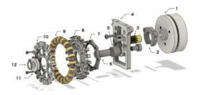
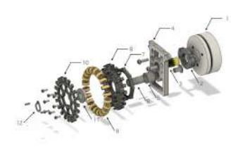
We are building our own drive unit shown in the above figure, and we are also building our own internal gears #7 for the reducer. This causes individual differences in the structure, which leads to problems such as unstable rotation performance of the wheel and different back-drive performance for each individual unit. The causes of individual differences are complex, but here are some of the causes that we have identified.
Machining and fixing method of internal gear
The internal gear#7 is made from A2017, a type of Duralumin. After cutting the gear lines using wire EDM (EDM), the threaded holes, contours, and flanks are machined using CNC milling and tapping. Between those two processes, the center of the part is often off-center. As a result, the misalignment that occurs during the machining of these parts and when the parts are fixed to each other has created individual differences in the meshing of the gears from wheel unit to wheel unit.
In order to reduce these individual differences, we decided to produce a part integrating the internal gear #7 and the part #8 by injection molding. This is because we thought that the injection molding process would reduce the machining process of the parts and also eliminate the individual differences that occur when the parts are fixed. However, we realized that the cost of manufacturing gears in this way was higher than expected and that it would be difficult to actually manufacture them. This is because the injection molding process requires the preparation of molds for the parts. Because the parts we need to make are complex in shape, we need to spend a large amount of money for mold machining. Therefore, we gave up the idea of manufacturing this part by injection molding.
Wheel wobble
One of the problems with the construction of the wheel part was that the bearing sometimes slipped out of the wheel while the robot was running. This caused the entire wheel to wobble as it rotated, resulting in poor gear meshing.
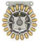

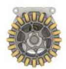
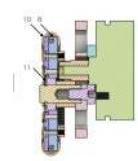
To prevent it, the structure around the bearing has been changed as shown above. In the new wheel unit, the flange of the bearing is sandwiched between parts #8 and #10. This reduces wheel wobble and improves the meshing of the pinion gear #3 with the internal gear #7.
Re-selection of rubber for side wheels
In the past, the robot had the disadvantage that the Omni wheel would spin during rapid acceleration, slowing down the robot's start of movement. The cause considered when focusing on the Omni wheel was that the side wheels were made of a hard urethane (A90) material, which has little grip and causes the Omni wheel to slip.
There are various types of rubber, each with different properties.
In general, softer rubber has better gripping performance. Soft rubber easily changes shape and grips objects that come in contact with its surface. However, soft rubber is less durable and easily deteriorates, making it unsuitable for longterm use.
On the other hand, hard rubber has poor gripping performance. This is because hard rubber does not easily change shape in response to objects that come in contact with its surface, making it difficult for it to exhibit gripping power. However, hard rubber is more durable and less prone to deterioration, which are desirable characteristics for long-term use.
Therefore, for robot wheels, rubber with moderate hardness, neither too soft nor too hard, is considered suitable. This time we prepared the same shape as the Omni wheel we have been using but with different hardness and materials and re-selected which material was most suitable for the side wheels of the Omni wheel.
Experimentation methods
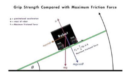
Three types of rubbers, urethane(A90), urethane (A70), and Chloroprene rubber (A65) were used in this comparison test. We defined gripping force as "the amount of frictional force generated between the carpet used in the game and the side wheels. The greater the frictional force, the greater the gripping force."
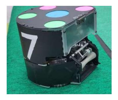
A horizontal metal plate is wrapped with the carpet used in the match, and the robot is placed on the plate. Since pure static friction cannot be obtained if the robot's wheels rotate at this time, tape the Omni wheels so that they do not rotate. An inclination was made on the metal plate to examine the angle θ at which the robot slides out.
Experimental results
From the above, we conclude that urethane with hardness A70 has the best grip of the three materials prepared.
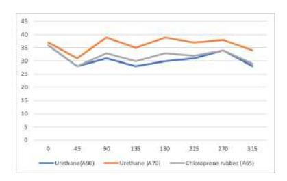

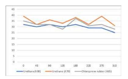
In addition, the following can be considered from these results.
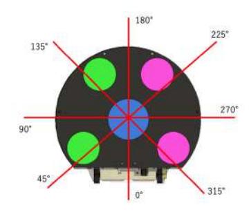
Gripping force changes depending on which angle the four Omni Wheels are facing in relation to the direction of travel, as shown in the figure below.
The ball-capture area is assumed to be in front of the robot.
When the robot is facing 0°, 90°, 180° and 270° to the sliding direction, the shafts of the four Omni wheels are oriented at 45° to the sliding travel direction. In this case, the gripping force was relatively large.
When the robot was oriented at 45°, 135°, 225°, and 315° to the sliding direction, some of the four Omni wheel shafts were perpendicular to the sliding direction and some were parallel to the sliding direction. In this case, the gripping force was weakened relative to the previous experiment.
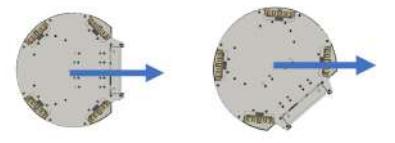
The gripping force depends on the position of the center of gravity.
The lower the center of gravity (in the direction of motion), the greater the gripping force.As shown in the figure, the inside of the robot is not symmetrical, so the center of gravity is slightly tilted to one side.Therefore, it is considered that the same rubber may have a difference in gripping force depending on the direction of motion.
The Challenge of the Reduction Gear Revolution
This section introduces the drive units that were not implemented in the actual machine.
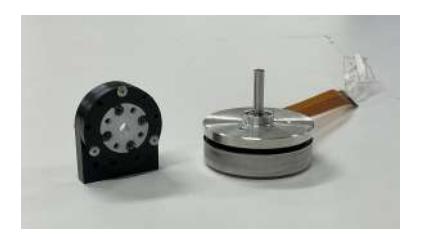
Drive Unit with Cycloid Reduction Gear
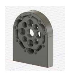
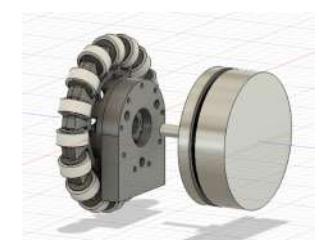
The reduction ratio can be higher than that of planetary gears. The motor on the right is an ECflat-45. A reduction ratio of 9:1 was achieved for a motor of this size. The motor mount is embedded with trochoidal curved gears to reduce the size of the motor. This was a challenging development, but it was abandoned because of its loud vibration noise.
Planetary Internal Gear Drive Unit
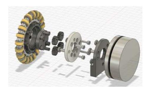
This drive unit has a different structure from the aforementioned internal gear. We gave up on this project because it was not suitable for SSL, which manufactures robots in large quantities due to a large number of parts. All the gears were machined at the EDM, a machine tool center located at the university. If we could switch from in-house production to outsourcing, we would be able to produce such a complex drive unit with a large number of parts.
Improvement of Motor Driver
Previously, our robot uses the maxon EC-flat45 30W with a driver based on the Roots motor driver. Roots[1] has created its own resource for robots available on the net. We can get and run their programs such as motor drivers and CON-SAI. We wrote a motor driver that mimics Roots, but couldn't realize their full features. Roots uses magnetic encoders, while our motor drivers only use hall sensors to recognize the electrical angle of electromagnets for motor feedback control. I have never applied his PI control program of robot rotation speed to this motor driver. On the 2022 motor driver, the duty ratio of Pulse Width Modulation (PWM) was given externally, and the voltage was converted to current to drive the motor. This is open loop control providing neither current nor speed feedback. Using a motor driver that does not read RPM with an encoder makes it difficult to achieve Sim-To-Real because it cannot handle individual motor differences. Also, the open-loop 120-degree current drive of brushless motors causes inefficient energy consumption due to heat generated by the motor.
Improvement Plan
We set a goal to implement FOC to improve the motor driver, there is an opensource project called SimpleFOC, which is a very powerful project to implement brushless motor control algorithms in many microcontrollers. I created a NUCLEO-F446RE project and tried using SimpleFOC, but the PWM did not work correctly. With regular ArduinoIDE it worked fine. We tried to use this as a reference to create a motor driver firmware in Mbed-OS5.
Motor Driver
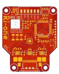
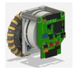
We have produced the following motor driver. This is our first self-made motor driver board. We used STM32F446RET6 as microcontroller, DVR8300DRGER as the gate driver, and SIZ254DT-T1-GE3 as MOSFET. The sensor is a current sensor using a shunt resistor and an upcoming flame coater AS5048A. CAN communication is supported.
Calculation of Gate Resistance
When making a motor driver, a MOSFET, and a gate driver are used, and the gate resistance must be selected correctly, as too much gate current in the MOSFET can destroy the gate driver. When building the motor driver, we obtained some parameters from the MOSFET datasheet and calculated the gate resistance value using Python.
Parameter:
– Maximum gate driver current = 1.5A – dead-time = 250ns – Ciss1 = 795pF – Ciss2 = 765pF – Qg = 20nC – Qgs = 2.7nC – Qdg = 1.8nC – Rgp = 1.2Ω
Results:
1 Cg : 1290.32 pF 2 IgMax : 0.303 A 3 period : 50000.0 ns 4 period Min : 195.3125 ns 5 timeTurnOn : 122 ns 6 Param : [ Rg : 50 omega , Vgs : 15.5 V ]
When this MOSFET is used and the gate drive voltage is set to 15.5[V ]and 50Ω is added to the gate resistor, the period is smaller than the dead-time of 250ns, and theoretically, it should be possible to drive the MOSFET without any problem.
However, the motor driver did not actually run correctly. Possible causes include the placement of the bootstrap capacitor. When using such ICs, it is necessary to correctly interpret the design reference in the data sheet and incorporate it into the design. The DVR8300DRGER used this time was in a QFN package. This was too small for human soldering.If you want the code, please refer my blog (https://tomixrm.vercel.app/ 2e7cb67096e143f2a43334a63c00d47e)
Circuit Development
This paragraph intentionally left empty.
Previous circuit
The above figure shows the circuit diagram of the DC-DC converter installed in last year's aircraft. This circuit consists of two parts. The circuit circled in red on the right is the step-up circuit, and the other part is the control circuit of the step-up circuit. The simple principle of operation of a voltage multiplier circuit
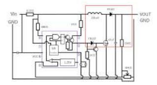
The figure above is a simplified version of the voltage multiplier circuit. First, consider the case when the middle switch is closed. The current flow at this time is from the DC power supply to the coil L to the switch so that no current flows through the resistor (output part) on the right side of the circuit. In other words, the circuit at this time is a DC-L circuit. The coil connected to the DC power supply is characterized by the fact that it does not change current rapidly, so the change in current with time rises relatively slowly. The voltage also has an electromotive force of $\Delta I/\Delta t$ . Also, since self-induction occurs while current is flowing in the coil, energy continues to accumulate in the coil. Next, consider when the switch in the middle is opened. At this time, the current flowing through the coil suddenly becomes zero. As mentioned earlier, since voltage is obtained by $\Delta I/\Delta t$ , the voltage at this time is larger than the power supply voltage. The equation is $W=\frac{1}{2}I^2L$ , so when the switch is turned off, energy proportional to the square of the current is released.
By switching this switch in a certain time, a voltage boost is achieved. However, if this is not done, the waveform of the output voltage becomes triangular in the range of V>0. The role of capacitor C on the right is to smooth this waveform. This capacitor smoothes the output voltage waveform by storing the output voltage when the output voltage is high and discharging it when the output voltage is low.
Control of the voltage multiplier circuit When performing voltage multiplication in the circuit shown in the above figure, it is important to switch the switch at the right time. The ratio of the time the switch is on is called duty ratio, which can be obtained by D=1- Vin/Vout. The detailed derivation process of this formula is omitted here, but the higher the duty ratio, the higher voltage can be output (if the duty ratio is set to 1, the coil will burn out). The left side of the above circuit controls the duty ratio. This circuit is mainly composed of MC34063A.
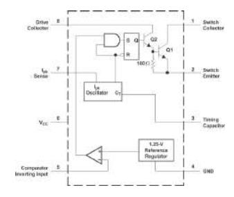
The above figure shows the MC34063A Datasheet. Among them, the following red line is the part that simply switches by the time ratio.
When a capacitor is connected to pin 3, it is possible to change the interval (frequency) between the voltage waves by the capacitor. The relationship between the capacitance of the capacitor and the duty ratio is shown in the graph in section 7.9 of the datasheet.
From the experimental results, the capacitor was fully charged in 23 seconds when the input voltage was 16 V and the output voltage was 205 V. This time was a big advantage in the match. In addition, the results of the experiment showed that the capacitor was fully charged in 23 sec. Since the maximum duty ratio is 1, it is difficult to increase the voltage significantly by changing the capacitor connected to the third pin. From the above, there are several problems with the current circuit. 1.
- power adjustment of the kick, lack of power
- safety issues due to lack of insulation between high voltage and low voltage sections
- slow charging time of the capacitor makes it difficult to kick continuously.
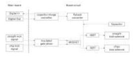
To improve the above problems, a new kicker circuit was developed. The specific principle of operation of the new circuit is as follows Two 2200µF capacitors are charged by a flyback type voltage booster circuit using IC:LT3750. The kicker circuit uses a gate driver Adum5230 and IGBTs. When a signal is sent from the main board, the IGBTs discharge the 200v charged in the capacitors and the solenoid is activated. The gate on time of the IGBTs can be controlled by the main board, making it possible to control the strength of the kick.
Power adjustment of the kick
From the above, it is difficult to boost the voltage any further with the conventional voltage booster circuit, making it impossible to increase the power of the kick. To improve this problem, a step-up circuit was designed using the flyback method instead of the conventional step-up chopper circuit. As a result, the number of transformer windings allows for easy voltage boosting. Specifically, the use of a transformer with a 10:1 turns ratio, transformer:750032052, increased the output voltage from 150v to 200v, enabling a more powerful kick. Two channels are used for discharge, allowing for straight and tip kicks.
Safety aspects
Previously, a commercially available non-insulated DC-DC converter was used due to its cost and size. However, to protect the low-voltage side of the input from dangerous output voltages, the new circuit uses isolated DC-DC converters. The new circuit uses a transformer to isolate the input from the output, and the gate driver ADUM5230 also isolates the boost supply side from the control side. In these two respects, the design is more safety-conscious. However, the use of a transformer has made the circuit larger, so downsizing and weight reduction of the circuit is an issue to be addressed in the future. The block diagram of the newly designed step-up circuit is shown below.
About charge time
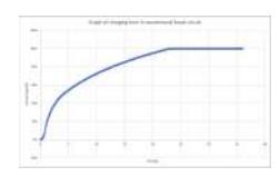
The LT3750 capacitor charger controller IC enables charging large capacitors to the target voltage at a faster rate. Also, in the aspect of kick power regulation, the use of IGBTs instead of MOSFETs has increased the switching speed and made it faster. The following graphs show the charging times of the old circuit and the new circuit. The charging time was measured by measuring the voltage across the capacitor with an Arduino. The conventional boost circuit took approximately 23 seconds to fully charge the capacitor, whereas the new circuit was able to complete charging in only a few seconds. From the above, the charging time was significantly reduced and continuous kicking was possible.
Software Development
This paragraph intentionally left empty.
RACOON-MW
We use our "middle-ware" tool named RACOON-MW (stands for Ri-one ssl Accurate Operation Middle-Ware) required to work with the centralized strategy system we use, RACOON-AI, and servers. It works as an intermediate between the vision, referee, and RACOON-AI. The software is programmed in Golang since it has "Goroutine" to facilitate parallel and concurrent processing. The functionality allows us easily receive data from multiple hosts, vision, game controller, and each robot, via User Datagram Protocol (UDP) multicast. It receives the sensor information of each robot via UDP as well. The received data is processed by Kalman filter and passed to the strategy system. RACOON-MW sends information to RACOON-AI at 60RPS and uses UDP for real-time communication.
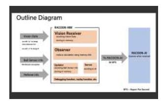
Vision Receiver receives Geometry Data, Blue Robots and Yellow Robots data, and Ball data from Vision as needed. When multiple objects such as a ball are acquired, only the most reliable ball is recognized, and the coordinates of the ball are obtained more accurately using a Kalman filter. In addition, with Observer, various statuses of all robots and ball such as the velocity vector, are calculated from the difference between the last accumulated frame and the current value. The Updater receives data from infrared sensors and retrieves ballholding information for each robot on its team. The Referee Client collects referee information received from the Game Contoller, such as referee command, keeper id, number of yellow cards and red cards, etc. The Server collects various data (own team's robot, enemy team's robot, ball, geometry, referee, and other) into a single packet called RacoonMW-Packet and sends it to RACOON-AI. IMUReset, which initializes posture of Intermediate Measurement Unit (IMU) signal such as angular velocity and speed to zero, and FPSCounter, which estimate the frame rate using the number of times a specific function is executed.
Apply of the Kalman filter
In previous competitions, raw values without any filters were used in the velocity calculations, but the robot frequently oscillated. We decided to implement the Kalman filter to resolve these problems. We used grSim's Gaussian noise generation function for the evaluation. To filter the xcoordinates of the ball, the deviation of the generated values was set to 13, where GroundTruth is 0.
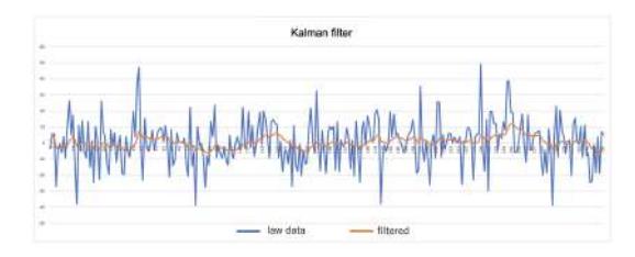
The blue axis is the raw data and the orange line is the filtered result. These results show that the post-filtered values are closer to 0.
Placement of Robot
In creating our tactics, we first assumed the use of eight robots, each with the role of offense, defense, and goalie. Three of the robots were given the role of offense.
Placement of Offense
Since we have assigned one of the offensive robots the role of an attacker to go to the ball, we will describe the placement algorithm for the other offensive robots. In implementing this algorithm, we focused on ease of maintenance. The three robots, including the attacker, are basically evenly spaced along the y-axis. In the x-axis, the center robot is positioned behind the ball and the side robots are positioned in front of the ball. This position is dependent on the position of the ball, so that it is always placed in the optimal location.
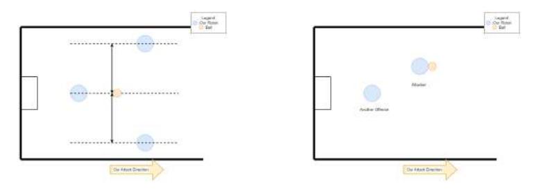
If the number of offenses is reduced to two, one is functioning as an attacker and the other is placed behind the ball, as described above.
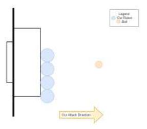
Placement of Defense
Four robots are assigned to the defense and we will describe how they are arranged. The four robots are arranged in a line around the goal area, like a wall. This arrangement can be moved according to the position of the ball, therefore the robots can stop the opponent's shot.
Conclusion
In this paper, we have discussed and introduced our new improvements. As we discussed in this paper, our team have been focus on developing our software system and machine hardware itself, and our improve should lead us to win the championship. Still some of them are under development, however, we will continue developing to make success in the competition.
References
[1] Roots-SSL. "Circuit BoostConverterBoard"-Robocup SSL Team. https://github.com/SSL-Roots/Circuit BoostConverterBoard [2] Team Roots, Design Data JapanOpen 2019 Ver. https://ssl-roots.github.io/Roots home/roots/robot jo2019 (2023/1/2) [3] TEXAS INSTRUMENTS."DRV8300DRGER".TEXASSNSTRUMENTS https://www.ti.com/product/DRV8300/part-details/DRV8300DRGER2022 (2023/1/2) [4] Ri-oneSSL GitHub [5] Friction Angle Easy-to-understand High School Physics Room https://wakariyasui.sakura.ne.jp/p/mech/masatu/kaku.html