RoboFEI 2023 Team Description Paper
Alvaro D. Neto, André L. Marques, Bruno B. Correa, Felipe E. C. de Mello, Guilherme M. R. Kashihara, Guilherme W. Cardoso, Henrique B. Simões, João V. L. Aguiar, Leonardo da S. Costa, Nityananda V. Saraswati, Rafael M. Cukier, Thiago O. Aravena, Flavio Tonidandel, Plínio T. A. Junior, Reinaldo A. C. Bianchi
Robotics and Artificial Intelligence Laboratory Centro Universitário da FEI, São Bernardo do Campo, Brazil
Abstract This paper presents the current state of the RoboFEI Small Size League team as it stands for RoboCup International Small Size League competition 2023, in Bordeaux, France. The paper contains descriptions of the new mechanical and electronics design, as well as an update to the software architecture.
Introduction
During our last RoboCup a lot of electronic problems appeared, probably due to not using the robots for two whole years. The result is that we had to play with less than three robots during the whole competition. Because of that, a lot of effort has been put into producing a new generation of electronic boards to control our robots, that includes: a new motor control board, a new main board and an update to our old kick board. In the following sections we will present the rationale for the choices that we have made, what worked, what didn't work and the final project that we hope to bring to this year competition.
Since we were changing our electronic boards, we decided to make a few changes to our mechanical design as well. Those changes aimed to fix some chronicle problems that we had in our robots since the beginning, e.g. bad ball dampening, low dribbler speed and non modular design, which increases the maintenance time of the robots.
Regarding the software, during the recent years we've made some significant progress, however, the previous architecture based on a single state machine ended up being hard to maintain. Therefore, we've adapted all of our code base to the well known Skill, Tactics and Plays (STP) [1] architecture. In the following sections we will give some details about our implementation as well as some advantages that we've gained with this change.
Mechanics
Introducing Robot Generation 2023
For RoboCup 2023, RoboFEI team will adopt a new generation of electronic and mechanical designs, introducing a new modular concept to provide maintenance and adjustment in a more practical and easier way.
The changes of the mechanical project are due to a need for the team to update our robots to maintain the same level of development as the league. In addition, some changes were made to the robot wheel design. The v2023 robot design is shown in Fig. 1 and the specifications are in Table 1.
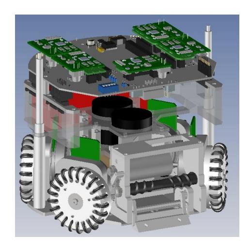
Table 1. Robot Specifications
| Robot Version | 2022 | 2023 |
|---|---|---|
| Dimension | ∅179 x 150mm | |
| Total weight | 3,5Kg | 2,5Kg |
| Driving motors | Maxon EC-flat-45 50W 18V | |
| Gear | 3:1 | |
| Gear type | Internal Spur | |
| Wheel Diameter | 54mm | |
| Encoder | US Digital E4T-1000-157-S-H-M-B | |
| Dribbling motor | Maxon EC-max-22 25W 18V | |
| ∅ Dribbling bar | 16mm | 9,5mm |
| Kicker charge | 2 x 2700µF @ 200V | 2 x 1000µF @ 200V |
| Microcontroller | Xilinx Spartan 3 FPGA | STM 32F4011 |
| Sensors | Encoders, Gyroscope and Accelerometer | |
| Communication link | nRF24L01 transceiver, 2Mbps, 2.4/2.5GHz | |
| Power Supply | Li-Po Battery, 11.1V nominal, 2200mAh |
Modularity Concept
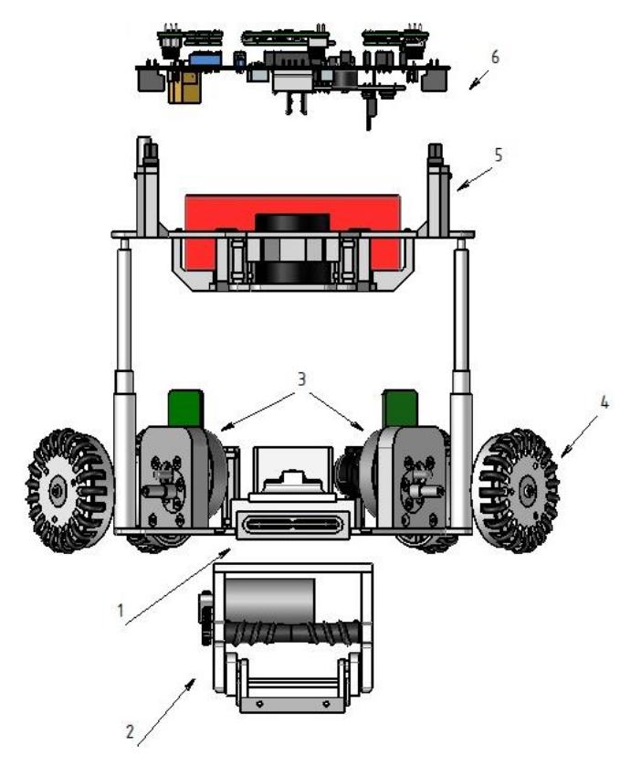
This year, major updates were applied on the mechanical structure of the robot, one of them was the modularity concept. With this update, the development and repair of the robots became easier, and now it is only necessary to release a few screws to disassemble the wheels module, for example. Each robot has five modules that can be replaced as a whole, this can be seen in Fig. 2.
- Bottom module: is the base plate, where the kick system, the dribbler and motor support modules are mounted;
- Dribbler module: it contains the dribbler motor, dribbler bar and gear transmission. In order to increase performance during a match, major changes were made in this module, these changes will be explained in the next section;
- Motor support module: it includes the wheels motor's and the encoders. Many updates were made on this system and be seen on our 2019 TDP [2];
- Wheels module: it contains the base of the wheel, gear and O'rings. Some updates were also made in this module, which will be explained in the following sections;
- Upper module: because of the many updates that took place this year, the upper module had to be completely refurbished to accommodate the battery and new electronic boards.
- Electronics Module: it contains the main and kick boards.
One of the disadvantages of the old structure is that it was made in its majority of aluminum and steel parts, which made the robot quite heavy and expensive. The new structure is mostly made of 3D printing, which makes our robots lighter, faster and cheaper than the old ones. Currently we aim to participate in division A and be a competitive team in it, to achieve this, most of our efforts are in reducing the cost to produce more robots, whilst maintaining its quality, in order to reach eleven robots.
Dribbler Module
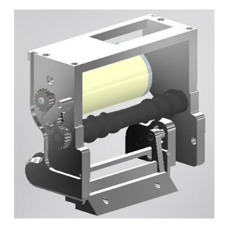
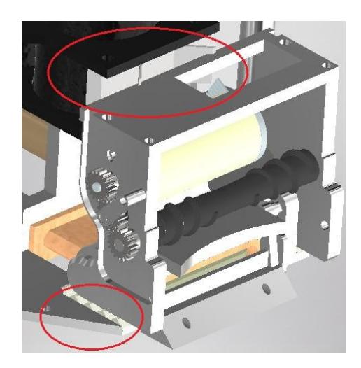
Currently in the small size league, the dribbler module has become extremely important to have a good performance in a match. Who has the best ball control ends up performing much better than other teams. The old system used was no longer attending the requirement of the games, because of that, the dribbler module was completely remade taking as inspiration teams that already have a good ball control [3,4,5,6,7]. This new module is represented on Fig. 3.
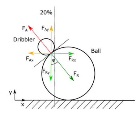
The first step we followed was to increase the height of the dribbler, this idea was taken from the ER-Force 2019 ETDP [3]. At the Fig. 4 it's possible to see that at the point of contact between the ball and the roller, two forces are created: the force $F^A$ of the ball acting over the roller, and the force $F^R$ of the roller acting on the ball, these two forces act perpendicular to the tangent at the point of contact. These forces can be decomposed into their vertical and horizontal components (Fax, Fay, FRx, FRy), which helps to understand the problem. On the Fig. 4 it is possible to see that the force FRx pushes the ball away from the robot, but this force can be decreased if the point of contact is raised higher than the current height. However, because of the rules of small size league [8], the maximum allowed ball coverage is 20%. Therefore, there is a limit on how high the dribbler can be placed. To solve this problem, the diameter of the dribbler was reduced to 10mm, making it possible to relocate the contact point of the ball, minimizing the force FRx.
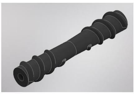
As the dribbler size already had to be updated, further changes were made on it. Firstly, the material of the dribbler was changed to silicon, with a hardness of 50-60A shore, in order to increase the grip between the ball and the robot. To reach that, different molds were developed to be 3D printed, which facilitates eventual design changes, in addition to be a cheap method. The Fig. 5 shows the new design.
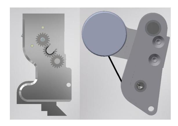
Another update that was made in the dribbler module was the change from a belt transmission to a spur gear transmission. This was done because the old system had a high degradation, losing performance with time. Now the transmission system contains three gears with a pitch diameter of 9mm and a module of 0.5, as shown in Fig. 6. Therefore, it was possible to achieve the expected result, the system became more robust, with less decrease of performance after the tests were realized.
In order to perform a good ball handling during a game, it's necessary to have good dampening to receive passes and keep possession of the ball. However, the previous dribbling module couldn't perform any of these functions as desired. In order to improve this problem on the robots, an inverted pendulum method was adopted, where many inspirations were taken from the Team TIGERs [6,7]. The comparison between the new dribbling damper and the old one is shown in Fig. 7.
Beyond this, we added two dampers, the upper one helps to absorb impacts from passes and kicks, and the bottom one helps to maintain the stability of the ball control. These dampers were made using flexible TPU hardness D40 shore, as this makes manufacturing and possible future updates easier thanks to being a material that can be 3D printed. The dampers are shown in Fig. 8.

Upper Module
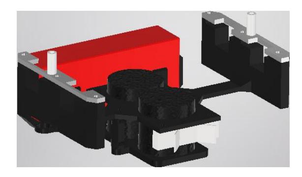
The change in the upper module came in the change of the capacitor, the new one has $\varnothing 30, 50 \times 35mm$ of size and $1000\mu F @ 200V$, in comparison to the old capacitor $\varnothing 35 \times 60.5mm$ of size and $2700\mu F @ 200V$.
After performing some tests, the team concluded that had more capacity than needed, therefore the components were out of scope for this project. Another change in the build of the final version was to accommodate the new main board and battery in the upper module, as shown in Fig. 9.
Wheels Module
A good motion is a necessary skill to achieve great results in the Small Size League. Because of that, after some competitions, it was realized that the structure of the past wheels was complicating the team in some situations, like skid in the field when accelerating or decelerating. The main points was the large distance between the rollers arranged perpendicularly for omnidirectional movement and the weight of the wheels. So, the team decided to develop a new generation of wheels.
Four prototypes with different features were machined and tested. The first prototype kept the same 54mm of diameter, but had 20 rollers instead of 16 of the past structure. The second prototype kept 54mm of diameter, but had 21 rollers and was used to understand the differences when adding one roller to the structure. The third prototype was developed with 44mm of diameter with 15 rollers and was developed to understand the effects of decreasing the diameter. The fourth prototype was developed using as base the OP-AmP model [9], where they presented a model that has two layers of rollers stacked alternately. The CAD rendering of the four prototypes developed is shown in Fig. 10.
The prototypes were tested using the same robot and the same test scenarios, which is a 1m side square. The prototypes were evaluated according to the following criteria: weight of the assembled wheel, quality of finishing and machining, torque (τ) and velocity (v) provided, changes in the original design and the quality of the motion in the field. According to this, Table 2 shows the results of the tests and analysis of each prototype.
After that, the prototype chosen to be the new design was the second, even though the quality of finishing was medium, but a better machining should work well to solve this. The second prototype also showed a better quality of motion in the field than the first one. The third and fourth prototypes were not chosen because of the difficulties on adapting them to the robot structure.
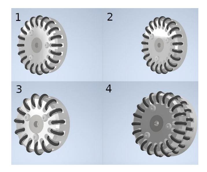
Table 2. Comparison between the four prototypes developed.
| m [g] | Machining quality | τ [mNm] | v [m/s] | Changes in the original design | Motion quality |
|---|---|---|---|---|---|
| Original 101 | Good | 207.67 | 4.8443 | — | Medium |
| ◦ Model 1 85 | Good | 207.67 | 4.8443 | Easy | High |
| ◦ Model 2 83 | Medium | 207.67 | 4.8443 | Easy | High |
| ◦ Model 3 66 | Good | 207.67 | 3.9472 | Hard | High |
| ◦ Model 4 127 | Good | 207.67 | 4.8443 | Medium | High |
Electronics
For all of our electronic designs we chose KiCad [10] as development tool. The reasons for using it are mainly due to it being open source, cross platform and it also has a simple and intuitive interface.
We will be releasing all of out schematics and layouts for the open source award. In the meantime, some final adjustments regarding documentation and organization will be made before it goes public.
Motor Control Board
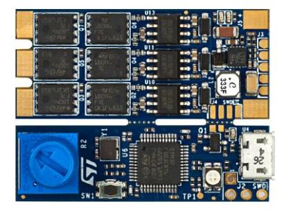
For the 2023 design we went with the modular concept shown in the 2020 TPD [11]. Since we needed to build a prototype as fast as possible, we needed a motor controller that was easy to use, easy to build and had practically no chances to not work. Therefore, instead of using the A4915 Integrated Circuit (IC) with the IRF8313TRPBF MOSFET, we decided to use a commercial Electronic Speed Controller (ESC), the STM B-G431B-ESC1, which can be seen on Fig. 11.
According to the data sheets [12], this ESC is capable of handling peaks of 40A, controlling Brushless DC (BLDC) Motors using the six step algorithm and is also capable of Field Oriented Control (FOC). It is possible to control the board using a PWM signal or CAN protocol, although the latter did not provide a good control for our robots.
Since it is a development board, it has a ST Link board attached to make programming and debugging easier. However, the ST Link can be detached to reduce the size of the board, in that case, programming can be done using the Serial Wire Debug (SWD) pins.
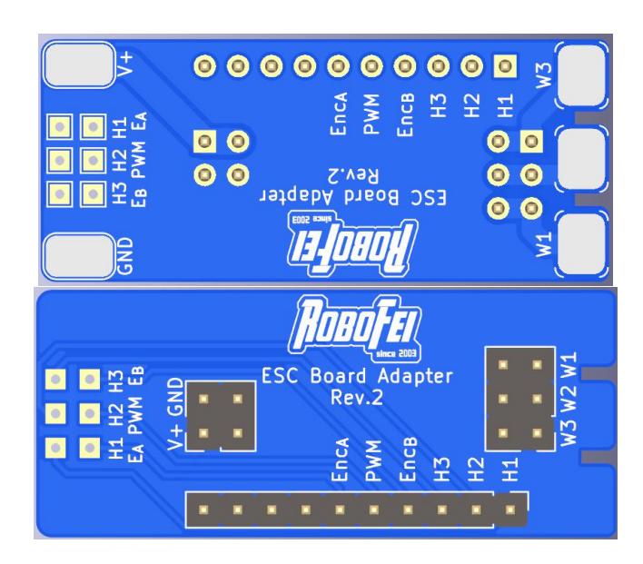
The B-G431B-ESC1 is designed to be connected to the external circuit by wires, however, given the space constraints of our robots it is mandatory that the motor control boards be attached to the main board via some kind of connector. In order to fix that, we developed a motor adapter board, which is soldered directly to the B-G431B-ESC1 and has a connector which will be inserted into the main board. The motor adapter board top and bottom views can be seen on Fig. 12. The main idea is that the big pads will be soldered directly to the ESC board, and the hall sensors (H1, H2, H3), PWM and encoder sensor (EA, EB) will be connected through wires.
This is the second version of this board, in the first one we used Mill Max surface mount pins [13] to connect the larger pads of the ESC and a cable to connect the other signals. However, not only it was expensive to buy all the connectors needed, but it also was very time consuming. Since this is the motor board, each robot need five of these. The new version of this board does not require us to assemble any cable, it is not needed to perfectly align the mounting pins in order to be able to attach the board, and the only thing that has to be bought is a few pin headers, which are cheap and can be easily found in Brazil.
Main Board
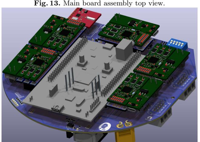
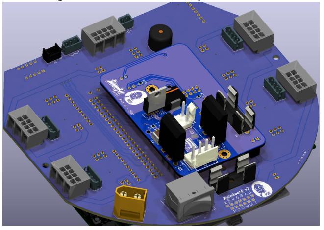
The main board is composed of the main processing unit, five motor control modules (four motors + dribbler), a few LED indicators, buzzer circuit, the radio module (nRF24L01), ball sensor circuit, a 5V voltage regulator (LM2596 IC) and the robot ID selector. Given that we are using development boards for the complex circuits, this design allows us to manually build the boards ourselves, since there are no chips that are hard to solder, the smallest are some SOIC-8 ICs and 0805 resistors and capacitors. The main board assembly can be seen on Figs. 13 and 14.
We went with the STM32F411 Discovery Board [14] for our main processing unit. Although it is not the most powerful board, it has some nice features, e.g. 3-axis digital output gyroscope and 3D digital linear accelerometer, which will be useful once we add those to our control loop.
Since we have practically six development boards, and each of them with its own 5V regulated output, in the first version of the board all of these 5V outputs were tied together. However, as it turns out, any voltage difference between the regulators, or delays in powering up or down, can (and most likely will) lead to catastrophic damage to any of the regulators. This mistake lead to a few of our STM32F411 boards burning out in the first few tests with the new electronic design. Although this seems to be common knowledge for those with a deeper understanding of voltage regulators, we decided to share our experience to hopefully spare new teams from making the same mistake.
In the final design, the LM2596 regulates the battery voltage down to 5V, in order to power all of the circuits in the board, and the extra voltage regulators are all left unconnected. This solved the problem we've faced in the first prototype and for the past months the new electronic board has been working properly.

Kick Board
Our kick board uses the same circuit seen on previous years. It is based on a buck converter, and, due to its simplicity we've been able to buy components in the current semiconductor shortage. The new changes focuses mostly on improving some board tracks that were poorly dimensioned in the previous versions, leading to a lot of maintenance of these boards.
Regarding the new design shown in our 2020 TDP [11], which is based on a flyback topology, a prototype has been built, but it still has some issues. We hope to be able to test at least one board during this year's RoboCup.
Capacitor Dimensioning
After a few tests in our lab we found out that, after using our strongest kick our capacitor voltage would only drop from 160V to around 100V, indicating that their capacitance was probably too large for our needs. Since our robots don't usually kick in a rapid succession, we decided to reduce the capacitance value in order to save some space inside the robot.
In order to do so, the capacitor formula (Eq. (1)) was used.
$$\overbrace{Q}^{i , dt} = C \times \overbrace{V}^{dV} \text{ or } i = C \frac{dV}{dt}$$
Therefore, for a strong kick, the time that we activated the solenoid is around $\Delta t = 6ms$, the voltage drop should be around $\Delta V = 160V$, and the estimated current is around 60A, thus, the capacitance can be calculated through Eq. (2).
$$C = \frac{i \times \Delta t}{\Delta V} = \frac{60 \times 0.006}{160} = 2250 \mu F$$
The above formula considers that the capacitor is able to provide 60A constantly, since this is not the case, two 1000µF capacitor should be able to cover our needs.
We are aware that this approach is greatly simplified, given that the current during activation is not constant. However, after performing a few tests with the double 1000µF capacitors it seems to be working appropriately.
Software
During the last year we've started implementing the STP architecture [1] into our software system. The main reason for that is the increased code organization provided by separating the team behavior into a play selector, which we call Coach, set of Plays, Roles, Tactics, and Skills.
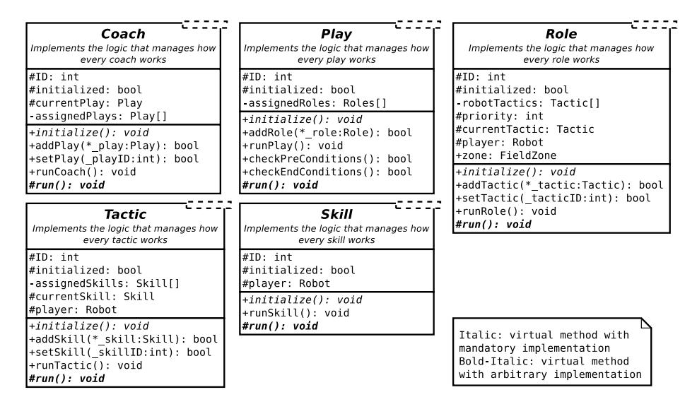
In order to make sure that the architecture works properly, our implementation uses a set of abstract classes, one for each component of the architecture, which contains the logic of how the architecture should works, i.e. how a coach executes a play, how a play executes its roles, and so on. This way, those who only want to create a new play don't have to think about how this will be executed. And it also reduces the risk that inexperienced programmers end up messing the logic that makes the architecture work. A class diagram with some basic implementation details can be seen on Fig. 15.
In order to implement the team behaviors one must only inherit from these classes and implement the logic of the play, role, tactic or skill. The ID is used to identify each implementation and must be unique among the same class type. The initialized flag is used to determine if the behavior has been correctly initialized by calling the initialize method, this is done automatically.
Most of the logic about how everything works is programmed inside the run{Coach/Play/Role/Tactic/Skill}() methods, which must not be overloaded. In case the user wants to customize something that happens inside the run{*} method it can implement the run() method.
Regarding the role class, it has a few different attributes, such as: priority and zone. Since each play allocates which robot will execute each role, the priority determines the order that each role must be filled, e.g. the role of the robot that will dispute the ball is more critical than the role of some lurking robot, therefore it must be assigned first.
The zone defines a certain area of the field which the role will be executed, e.g. the role of the robot that will kick the ball during the kickoff is delimited by a circle around the center of the field. The zone helps the play allocate robots in a way that each robot will go to the closest zone when there more than one role with the same priority.
This architecture tremendously increases the capacity to make elaborate plays when compared to a single state machine. By combining this, with the possibility to emit events using the Qt framework, it is possible to coordinate play much easier.
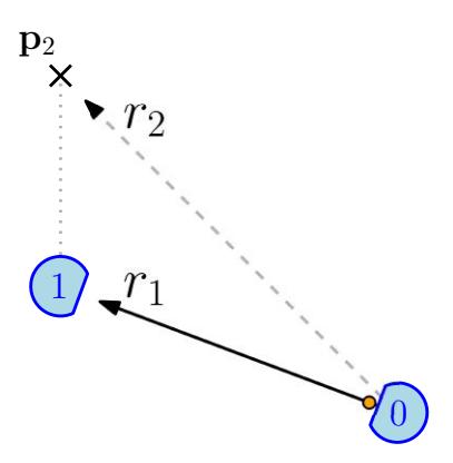
One example of that is making a pass to a future position. For example, lets consider the situation seen on Fig. 16, a pass along the line $r^1$ would be easily intercepted, if not already blocked, considering the position of the robots. However, if robot 0 made a shot along the line $r^2$ synchronized with the arrival of robot 1 at p2, it would be much harder to intercept or block that pass.
This type of coordination can be achieved using timers and events which are available under the Qt framework, and the fact that each play, role, tactic and skill is a class on its own, greatly facilitates the usage of these framework features.
Acknowledgements
We would like to thank, in advance, the Small Size League Committee, for the consideration of our material. We would also like to immensely thank the staff of Centro Universitário FEI, for all the help we always received from them.
References
- Brett Browning, James Bruce, Michael Bowling, and Manuela Veloso. Stp: Skills, tactics, and plays for multi-robot control in adversarial environments. Proceedings of the Institution of Mechanical Engineers, Part I: Journal of Systems and Control Engineering, 219(1):33–52, 2005.
- Guilherme P de Oliveira, Vinicius M Alves, Danilo Pilotto, Wesley de S Motta, Leonardo da S Costa, Guilherme Luis Pauli, Marcos AP Laureano, Carlos Alberto F Cadamuro, Reinaldo AC Bianchi, Plinio Thomaz Aquino Junior, et al. Robofei 2019 team description paper. 2019.
- Theresa Engelhardt, Tobias Heineken, Tobias Kuehn, Jeldrik Lindner, Mike Schmidt, Felix Schofer, Christian Seifert, Michael Stadler, Lukas Wegmann, and Andreas Wendler. Er-force 2019 extended team description paper. 2019.
- Zheyuan Huang, Lingyun Chen, Jiacheng Li, Yunkai Wang, Zexi Chen, Licheng Wen, Jianyang Gu, Peng Hu, and Rong Xiong. Zjunlict extended team description paper for robocup 2019. arXiv preprint arXiv:1905.09157, 2019.
- Zheyuan Huang, Haodong Zhang, Dashun Guo, Shenhan Jia, Xianze Fang, Zexi Chen, Yunkai Wang, Peng Hu, Licheng Wen, Lingyun Chen, Zhengxi Li, Xiong, and Rong. Zjunlict extended team description paper for robocup 2020. 2020.
- Andre Ryll, Mark Geiger, Chris Carstensen, and Nicolai Ommer. Tigers mannheim extended team description for robocup 2018. RoboCup Wiki as extended team description of TIGERs Mannheim team, Montreal, Canada, accessed March, 6:2019, 2018.
- Andre Ryll, Nicolai Ommer, Mark Geiger, Malte Jauer, and Julian Theis. Tigers mannheim. 2020.
- RoboCup. Rules of the robocup small size, may 2023. Accessed in 25 Jan. 2023.
- Takamichi Yoshimoto, Takato Horii, Shoma Mizutani, Yasuyuki Iwauchi, and Shota Zenji. Op-amp 2019 extended team discription paper. Technical report, Technical report, Asagami Works, Osaka, Japan, 2019., 2019.
- KiCad. Kicad eda schematic capture & pcb design software, 2023. https://www.kicad.org/. Accessed in 25 Jan. 2023.
- Leonardo da S Costa, Wesley de S Motta, Danilo Pilotto, Guilherme L Pauli, Joao VL Aguiar, Gabriel M Schiavetto, Bruno Bollos Correa, Mateus Mariano Lucatelli, Marcos AP Laureano, Reinaldo AC Bianchi, et al. Robofei 2020 team description paper. 2020.
- STMicroelectronics. B-g431b-esc1 discovery kit with stm32g431cb mcu, 2023. shorturl.at/csUW4. Accessed in 25 Jan. 2023.
- Mill Max. 1440-4-00-80-00-00-03-0 datasheet, 2023. shorturl.at/oST16. Accessed in 25 Jan 2023.
- STMicroelectronics. Discovery kit with stm32f411ve mcu, 2023. shorturl.at/mqwNO. Accessed in 25 Jan. 2023.