SRC Extended Team Description Paper for RoboCup 2023
Yuhong Tan, Liangcheng Jiang, Juntong Peng, Ziming Chen, Zhaoyang Li, Yun Bao, Yujia Zou, Rui Shi
Student Innovation Center, Shanghai Jiao Tong University, P.R.China
Abstract This paper introduces the improvements which the SRC Team made in the last year. Through improvements in supporting point calculation, coordinating attacking strategy, skills improvement-BREAK, a more intelligent decision algorithm is realized. And in the electronics part, a specific embedded main program flow is introduced. We hope to do well in RoboCup 2023 based on these improvements.
Introduction
We are the SRC Team of Shanghai Jiao Tong University. We had our first small-size league competition in 2017. Since then, we have been locating problems and discussing where we can improve. In the past year, we made significant progress on software and algorithm development. Parallel computing with GPU acceleration has been introduced to our algorithm for the first time. We have made thorough reconstruction on the attacking strategy, enabling the robots to act with better collaboration. Additionally, new skills are designed to achieve better possession and better passing. At the same time, despite encountering frequent lockdowns due to COVID-19, hardware development has been continuously marching forward in the past 2022. We'll describe the improvements we've made over the last year in detail later.
Software
The software improvements include coordinating attacking strategy, supporting point calculation using GPU, and skills improvement-BREAK.
Coordinating attacking strategy
In today's game, the size of the field has changed from 96 square meters to 129 square meters, and the number of participating robots has changed from 6 to 11. Because of the increase in defenders and the size of the field, a single attacker can no longer easily form an effective attack, and the once-designed set-piece tactics hardly function as a direct shot or even a score now. Therefore, we have proposed a more reasonable coordinating attacking strategy this year, which greatly enhances the offensive capability of SRC.
For ease of presentation, we make the following provisions for the eleven-robot formation: one Goalie, four Defenders, five Supporters, and the Advancer, which is the main attacker with the ball. The advantage of this strategy is that the roles are not tied to the robots but are dynamically matched to the robot frequently.
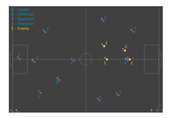
Dynamic matching
Instead of differentiating all robots at the beginning and customizing specific tasks for each one, we first generate eleven tasks and eleven corresponding task points. Then we match the task points with the robots one by one. At this point, there is no difference between the eleven robots on the field, and which task the robots perform relies solely on the designed matching algorithm.
Assume that we now know the set of tasks T = {t0, t1, t2, · · · , tn}, which should be performed at the moment, the set of mission point coordinates Q = {q0, q1, q2, · · · , qn}, the set of robot coordinates P = {p0, p1, p2, · · · , pn}, then we expect to minimize:
$$f(P,Q) = \sum_{i=0}^{n} ||Q_i - G_i||_2$$
$$G \text{ is a permutation of } P$$
This matching process can be better achieved by using the Hungarian algorithm.
However, we consider that the Advancer should have a higher priority than the other robots, so we first find the robot closest to the Advancer task point and designate that robot as the Advancer. The other 10 robots are then matched for the tasks.
For the six robots involved in the attacking system (5 Supporters and 1 Advancer), all the Supporters have to do is just make a reasonable run and not directly get involved in getting the ball.
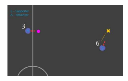
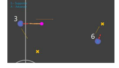
Role switching in passing system
Figure 2 and Figure 3 represents the robot role change before and after the pass action. Before the pass, the Advancer is about to pass to the supporting point, where the Supporter is heading. After the pass, the original Supporter becomes the Advancer, which needs to receive the ball, while the original Advancer becomes the Supporter, which needs to go to the new supporting point. This constant dynamic matching builds our passing system: The Advancer passes the ball to the Supporter, and then the two robot switch roles so that the attack is always initiated by the Advancer.
The Support algorithm is described in more detail in subsection 2.2, and the behavior of the Advancer will be explored next.
Task point generation
The selection of task points is very important for the establishment of the attacking strategy. For Supporters, Defenders, and Goalie, task point equals the running point. But the task point for the Advancer needs to be discussed further.
If the ball is at rest, the task point should be chosen as the position of the ball.
If the ball has a certain speed, then we need to consider the following two cases:
Our pass, while the opponent will not interfere.
Since we already know the passing point we wish to pass to, we directly use that point as the task point. However, if the ball is too fast for the robot to reach the pass point before it reaches the pass point, we need to predict the ideal catch position and move the task point backward a bit. This situation corresponds to Figure 4, Where the yellow X indicates the passing point and the red X indicates the task point. In most cases, the passing point and the task point are the same, when red X and yellow X overlap.
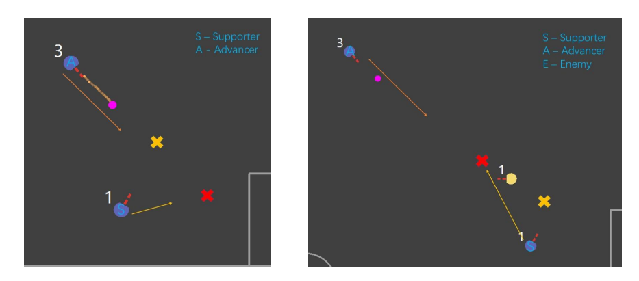
Opponent interference scenarios
An opponent pass, or the opponent will intercept our pass early we expect to catch the ball before the opponent, as shown in the Figure 5. The task point should be in front of where the ball speed line intersects with the opponent, so that the Advancer has a higher chance to get the ball. The yellow X indicates the passing point and the red X indicates the task point.
Offensive system construction
The overall system is shown in the Figure 6.

Offensive decision-making
The Advancer first considers whether it is holding the ball. If not, getting the ball becomes its main target. Meanwhile, it determines whether the ball is being passed to itself (by our robots).
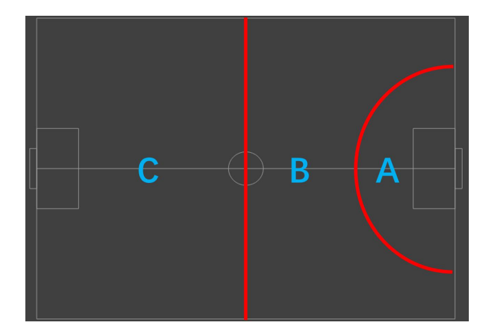
If Advancer holds the ball, referring to Figure 7, we consider a division of the entire field.
Field area strategies
Located in Area A.
We prioritize shooting. First, we generate the current optimal shot line, and if the opponent is far from the shot line, we consider shooting directly. If the opponent takes a tight defense, we use the skill mentioned in subsection 2.3 to shoot. Otherwise, we consider passing.
Located in Area B.
We prioritize passing. Assume that we have currently selected the Supporter to pass from among the 4 Supporters, i.e. we have a clear passing point. At this point, determine whether the opponent is closing in on our Advancer, and if so, make a pass using the skill mentioned in subsection 2.3. Otherwise, pass the ball directly. The specific execution of the flat pass or chip pass is judged by whether there is an opponent in the path of the pass for blocking.
Located in Area C.
We prioritize relieving. Advancer needs to Chip Pass to opponent's half.
Finally, we choose the reasonable number of Supporters and Defenders according to the scenario and make appropriate adjustments to the overall framework to get the final offensive system.
Selecting the reasonable passing point
We can obtain several points where the Supporters should logically arrive, assuming that the points are {p1, p2, p3, · · · , pn}. For a given passing point, we need to consider the following factors:
Passing feasibility:
- The distance from the Advancer to the passing point.
- The distance from the passing point to the closest Supporter.
Shooting feasibility after Supporter receives the ball:
- The distance of shooting.
- The angle of orientation adjustment.
- The minimum distance of the opponent from the goal line.
Several of the above factors are considered, and the approach we take is to construct:
$$f(X) = \sum_{i=0}^{m} a_i x_i$$
where the value of x^i is the normalized amount of the above factors, and the value of a^i is adjusted according to the actual situation. The final selection of the passing point is made by comparing f(Xi) for each passing point X^i.
Supporting Point Calculation Based on GPU
As the new coordinating attacking strategy is introduced to algorithm, a higher requirement on task point calculation is advanced. There are two main aspects of the cooperative attack: how the robot with the ball passes the ball over the opponent's defense to supporting robots or to the goal, and how the supporting robots find the best place to receive the ball. At the beginning of each attack, we need to calculate the optimal supporting positions where our Supporters can successfully receive the ball and advance the attack.
Using the powerful parallel computing capabilities of the GPU, we can take on more computationally intensive algorithms in the supporting point calculations. Samples are taken at certain steps in the field, some evaluation indicators are set for the sampled points, and the best points are then selected by algorithm. There are several evaluation indicators we are using as follows.
Crossing indicator
We connect the current ball position with each point and evaluate the point according to how much this line is obscured by opponent's robots versus our robots. The indicator aims to ensure that the supporting robot can successfully receive the pass at a proper point.
Shooting indicator
We assume the first goal of the receiving robot is to shoot directly. Therefore, we set this indicator to evaluate how much the shooting area is blocked.
Position indicator
Being too far or too close to the ball affects receiving, and some positions are not good for receiving and further action. The indicator filters out the inappropriate area of the field.
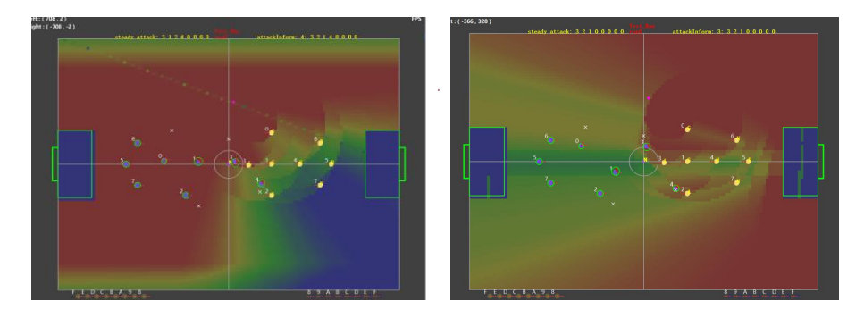
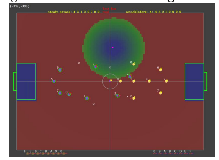
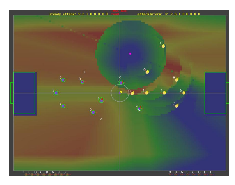
Using each indicator to estimate the points in the field, we can generate corresponding figures which we call "potential images" as follows.
Each figure shows the possibility of being chosen as a "supporting point" for each point in the field, using a specialized indicator. For each point colored in the figure, the closer the color is to red, the higher the rating, the more suitable to catch the ball, and the closer the color is to blue, the lower the rating, the less suitable to catch the ball. For example, if a point is colored red in Figure 8, it's very possible to be selected as the "supporting point" considering whether the position is suitable to receive the pass.
Field region selection and post-processing
Taking the weighted average of these evaluated values, we can obtain the final image as Figure 11.
Obviously, it is not appropriate to directly choose the best point from all the sampling points in the whole field as the supporting point, so some specific areas should be selected for searching in combination with the field situation. The algorithm should be more inclined to choose some areas in the front field to search when attacking, and more inclined to the back field when defending. Also, the supporting point should be kept at a distance from the ball carrier so that the supporting point is not too close to the ball carrier.
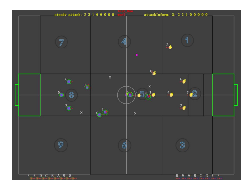
We have divided the field into 9 regions as shown in Figure 12, choosing the best supporting points in different regions in different situations.
Conflict resolution in supporting points
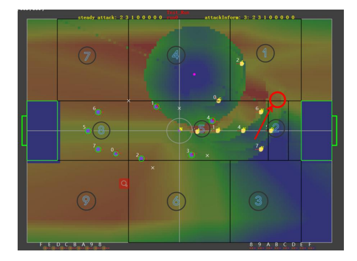
Even so, if we choose two adjacent regions, there may be a local optimum at their boundaries. Then the supporting points of the two regions will be very close in distance if no further treatment is done. For example, two supporting points in region 1 and region 2 are generated close to the border, as it is marked by the red circle in Figure 13.
Post-processing algorithm
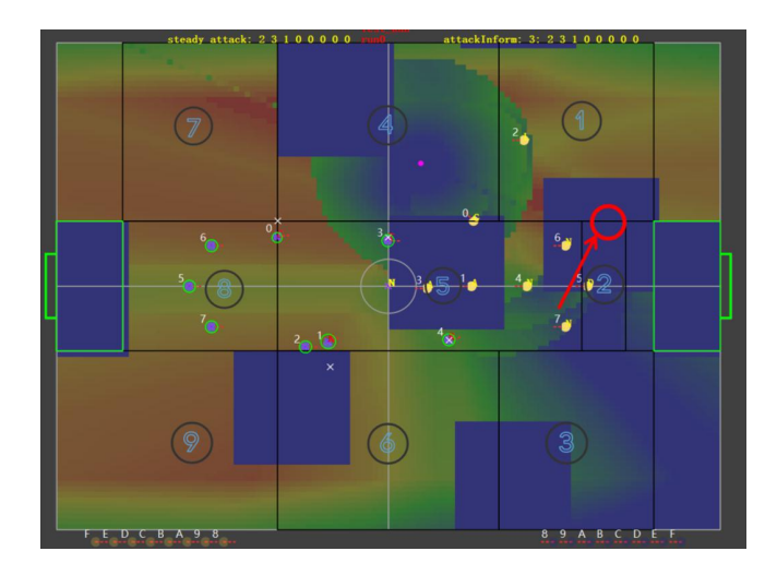
In this situation, the two close supporting points conflict with each other as the supporting point generated in region 1 is obviously redundant. Therefore, we designed a post-processing algorithm that makes the support points mutually exclusive to avoid this situation. The post-processing algorithm generates supporting points sequentially according to the region priority so that the post-generated lower priority supporting points are located away from the first generated points. For each generated support point, a blue rectangular area is generated with its center to reduce the possibility of subsequent support points being generated around it. Figure 14 shows the field potential image of the lowest priority point, and some areas are already occupied by the higher priority points, thus ensuring that the lower priority points are not too close to the higher priority points.
Skills Improvement-BREAK
Motivation and Overall Process
As the new strategies mentioned above are proposed, new demands are placed on individual skills. Normally, the robot dribbling the ball will be under the tightest defence. Therefore, it is necessary for us to develop the ability of breaking through the defense relatively individually for robots.
We developed our skill based on testing points and DP (Dynamic Programming), inspired by the previous approach proposed by ZJUNlict. The main task can be described simply as kicking the ball to a given point, which is currently blocked by enemies. To better demonstrate how our algorithm works, the whole process can be broken down into two parts. We have named them perception and decision making. In each vision cycle, percepting and calculating scores, checking kicking availability, deciding targeting dribbling destination will be processed sequentially.
Perception
The basis of the robots' actions is perception. To be more precise, the first step in breaking is to detect and evaluate nearby defences.
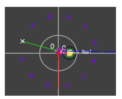
We first generate several testing points around the breaking robot (call it breaker), as shown in Figure 15. When generating points, we mainly consider rules restrictions including dribble distance and forbidden areas.
Evaluation of testing points
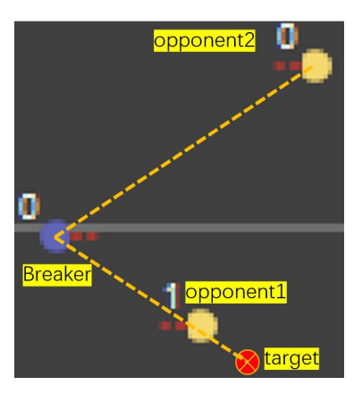
Then, the task converged to evaluating each testing point. For each individual robot, there are the following factors to consider. A simple demonstration is shown in Figure 16.
- The angle between the line with the opponent robot and the line with the target point. This represents the probablity of an opponent to sucessfully block the ball.
- The distance between breaker and target. This represents the maximum accuracy acquirable.
- The distance between breaker and the nearest opponent. This represents the probability of breaker getting stuck by opponents.
These factors can be easily calculated from the visual information. The ratio of the different factors is currently determined manually. In the near future, automatic parameter adjustment supported by reinforcement learning will be the alternative approach.
Decision Making
Normally, making the highest scoring checkpoint the breaker's target is reasonable and practical. However, there are situations where the breaker and an opponent fall into a cyclical movement when symmetrical checkpoints are selected alternately. So we add a sequence to record the latest selected points to make sure that the selected points have a universal tendency in one direction (if not, fix the current target for several frames to jump out of the cyclic movement).
Additionally, as the final goal is kicking the ball to a given point, whether it is able to kick successfully will be checked before making decision. Once the position is suitable, breaker will kick without hesitation.
Electronics
Our electronic system has maintained its structure since 2017, which includes two circuit boards, a control board and a power board. The power board is responsible for distributing the electric energy of the battery to all parts of the robot, including supplying power to the control board and driving the electromagnet to kick the ball. The control board needs to receive the command sent by the upper computer, analyze and execute it. So there are motor drive, wireless communication and sensor fusion modules on the circuit board. We use STM32F407VET6 as the main chip to coordinate the work of each module.
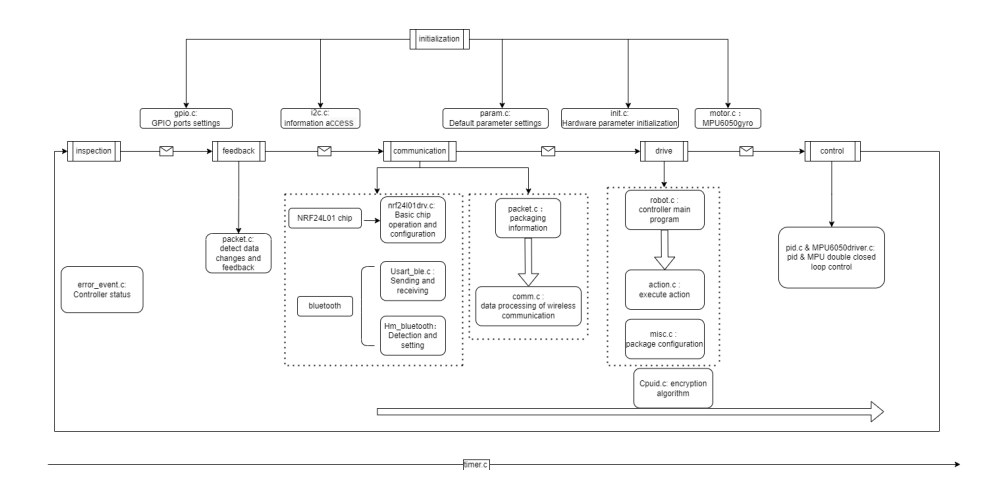
This year we mainly sorted out our embedded code running on the main chip to improve the performance of robots and meet the requirements of the competition. When the main chip starts, all parameters will be initialized first, including reading robot id, communication frequency, hardware parameters, etc. Then the program enters the self-inspection. If the controller status is wrong, it will report an error and light up. Otherwise, the program enters the main loop. The loop structure of the embedded main program is shown in Figure 17. It is mainly divided into three parts: communication, action and motor.
Communication module
After the system receives the data package from the host, it runs to the communication module including uploading robot status and unpacking packages. Because the signals we upload and receive use the same frequency, and the packages we need to receive are relatively more important, we upload in a trigger mode, that is, when the robot status changes, such as completing a kick, we will send five packets in a row, and then wait for the next trigger time. This will minimize signal collision and mutual interference, and save bandwidth resources. Then the program unpacks the data package and reads it. The communication protocol stipulates that there are four robots' information in a package. The information of each robot is ordered from small to large according to its own id, so the robot can easily take out its own information. Then the program will enter the action module and execute these commands.
Action and Motor control modules
The action module is mainly responsible for setting the target of each driving circuit, such as kicking force, wheel speed, etc. Finally, the program continues to wait to receive the command at the next moment, and the communication frequency with the host computer is basically the same as that of ssl-vision. Unlike the serial execution of the above modules, the motor module uses 500Hz system interrupt to control brushless motors at a higher control rate. It uses incremental pid algorithm to independently control four motors in closed loop. The system error is the difference between the wheel speed set by the action module and the current actual speed read by the encoder. By adjusting the parameters in the proportional, integral and differential control, we can improve the control performance of algorithm on motors.
Communication protocol
Communication protocol structure as shown in Figure 18.
Figure 18. Communication protocol
| Byte | Bit 7 | Bit 6 | Bit 5 | Bit 4 | Bit 3 | Bit 2 | Bit 1 | Bit 0 | Description |
|---|---|---|---|---|---|---|---|---|---|
| 0 (header) | 1 | 1 | 1 | 1 | 1 | 1 | 1 | 1 | Header |
| 1 (robots ID) | reserved | Robot11 | Robot10 | Robot9 | Robot8 | Robot x = 1, if the packet contains robot x's control instruction | |||
| 2 (robots ID) | Robot7 | Robot6 | Robot5 | Robot4 | Robot3 | Robot2 | Robot1 | Robot0 | Robot x = 0, if the packet doesn't contain robot x's control instruction |
| 3 (misc) | Dribble/forward 1: backward | 0: shot 1: chip 0,1,2,3: Dribble level | Higher 2 bits of v_x | Higher 2 bits of v_y | Control bits | ||||
| 4 (v_x) | 0: + The absolute value of x velocity (lower 7 bits), unit: 1 cm/s 1: - | First robot's control | |||||||
| 5 (v_y) | 0: + 1: - | The absolute value of y velocity (lower 7 bits), unit: 1 cm/s | Y velocity | ||||||
| 6 (v_r) | 0: + | The absolute value of axial velocity (lower 7 bits), unit: 1/40 rad/s Clockwise is positive | Rotation velocity | ||||||
| 19 | First robot higher 2 bits of v_r | robot higher 2 bits of v_r | Higher 2 bits of v_r | robot higher 2 bits | Extended v_r | ||||
| 20 | reserved | Shoot power | First robot instruction | ||||||
| 21 | reserved | Shoot power | Second robot instruction | ||||||
| 22 | reserved | Shoot power | Third robot instruction | ||||||
| 23 | reserved | Shoot power | Fourth robot instruction |
Conclusion
In the previous sections, we introduced our development efforts from the software and electronics sections respectively. In the software section, We introduced our new coordinating attacking strategy, mainly including dynamic assignment of player tasks according to points, automatic decision algorithm of robot holding the ball, parallel calculation of support points using GPU and other new skills. In the electronics section, we introduced the structure of embedded main program. Through these improvements, our system is more adaptable to the game of larger field and more robots, and we expect our robots to have better performance in Bordeaux.
References
- Zhao, Yue, et al.: ZJUNlict: RoboCup 2013 small size league champion. Robot Soccer World Cup. Springer, Berlin, Heidelberg, 2013.
- Munkres J . Algorithms for the assignment and transportation problems[J]. SIAM. J, 1962, 10.
- Juan Pablo Mendoza, Joydeep Biswas, Danny Zhu, Philip Cooksey, Richard Wang, Steven Klee, Manuela Veloso.: Selectively Reactive Coordination for a Team of Robot Soccer Champions. In:Proceedings of AAAI'16, the Thirtieth AAAI Conference on Artificial Intelligence, Phoenix, pp.3354-336
- Zheyuan Huang, Haodong Zhang, Dashun Guo, Shenhan Jia, Xianze Fang, Zexi Chen, Yunkai Wang, Peng Hu, Licheng Wen, Lingyun Chen, Zhengxi Li, and Rong Xiong, ZJUNlict Extended Team Description Paper for Robocup 2020.(2020)
- Jiawei Lin, Jie Chen, Baiji Chen, Kaichong Lei, Zikang shi, Jiaping He, Zhengwei Qin, Jiaxuan Xie, Jingwei Xu, Zhaocong Liu, Ruiqing Ge and Li Hao, SRC Team Description Paper for RoboCup 2020. In RoboCup 2020 (2020)