Sysmic Robotics 2023 Team Description Paper
Tomás Rodenas, Daniel Torres, Pablo Reyes, Javiera Peña, Claudio Tapia, Daniela Moya
Universidad Técnica Federico Santa María, Av. España 1680, Valparaíso, Chile
Abstract This paper briefly describes what the team has developed for the third generation of mobile robots, particularly the changes made since 2020 so far. The team's approach this year was to optimize the kicker system, restructure the design of the robot's prototype, the creation of a new client, changes in the wheels's mechanics and finally a new version of the data package sent to each robot. The topics involving our work, such as electrical, mechanics, software and firmware, were designed according to satisfy the Robocup rules.
Introduction
Sysmic, is a team of students from the Technical University Federico Santa María. The team first attended the Small Size League (SSL) in 2018 in Montreal by the name of AIS, obtaining a sixth place in Division B. The team stood partially inactive between 2020 and 2021 due to pandemics, and now intends to participate in the RoboCup 2023, Bordeaux. In this regard, there have been no significant changes to our mechanical and electrical design, other than those discussed in the following paragraph. The inability to work actively during 2020/21 slowed down the pace of work prior to the quarantines, and therefore we have maintained the vast majority of our designs until 2020 [5]. On the other hand, most of these changes come from our developments presented for the 2019 RoboCup [8], which we were not able to test in a competitive environment, and therefore we did not see the need to modify them substantially until we tested them in competition. Nevertheless, the following section summarises our TDP and the changes we have made from our previous design, as well as some of the ongoing developments we have in the software area.
In section 2, we briefly present the mechanical design of our robots and the modifications we have made to the drive train, moving to a gearless system because the torque characteristics of our motors are adequate for this operation, which provides us with a significant reduction of the space that was occupied by the gear system and has a direct influence on the cost of manufacture. Section 3 presents the changes made to the hardware of the robots, specifically a new kicking system that allows to charge the associated capacitors 6x times faster than our previous design. Section 4 addresses the changes made in the software area, presenting the current development of a new graphical user interface (GUI) for our client, as well as modifications in the communication packages between it and the robots.
Mechanics
Summary of structural design
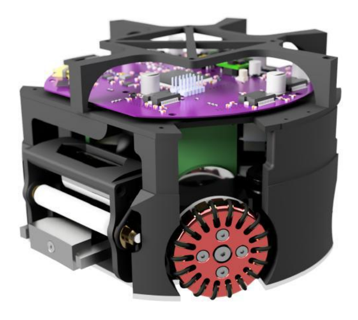
The current version of our robot generally has the same structure as our design submitted in our RoboCup 2020 application [5]. The main features of our mechanical design are:
- Structure composed of parts printed in PLA filament joined by two 3 [mm] thick Alucobond discs.
- Height of 13.5 [cm] and a diameter of 18 [cm].
- Upper case made of lightweight material, currently cardboard and potentially fiberglass.
- The external part of the wheels are 3D printed. One iteration of our design considered machining aluminum, but that was too expensive for our budget.
Figure 1 shows the design of our robot presented in our 2020 TDP. For more details of the transition from previous designs refer to the cited paper.
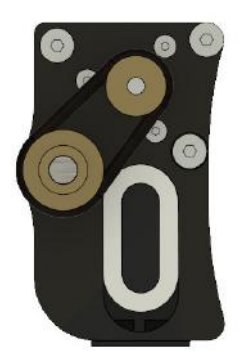
Another highlight of our current design is the dribbler. Inspired the Tigers Mannheim 2018 ETDP [6], we proposed a mobile design that solves the problem of null damping (see Fig. 2). The structure of the dribbler is made of plastic additive manufacturing (PLA with an FDM 3D printer), with two brass pulleys and an O'ring that transmit the motion from the motor to the roller. On the sides are oval silicone rings that allow movement between the part that holds the roller and the motor, with the support to the robot. The roller is placed at a height of 38 [mm] above the ground, with a diameter of 11 [mm], which means that the coverage of the ball does not exceed 13% of the surface of the ball when viewed from above.
Drivetrain modification
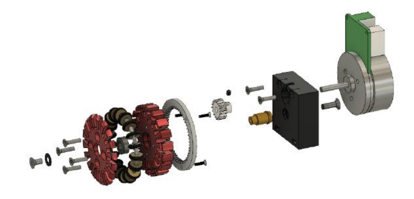
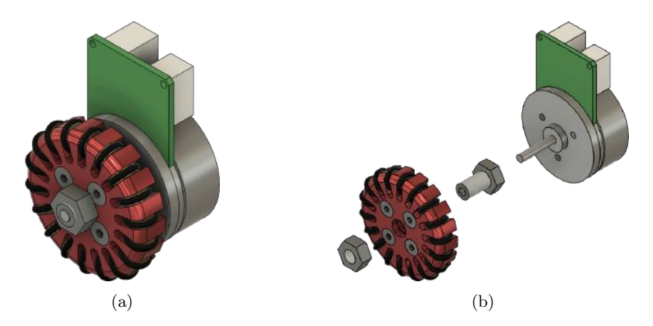
For this new version, a coupling was designed so that the wheel and the motor were directly connected, creating a single wheel lock system, this caused the elimination of the previously used gear system. This change gave us a decrease in the overall height of the robot by approximately 15 [mm] and a decrease in its radius by 2 [mm]. These changes are inspired by the modifications the Tigers Mannheim team made to its powertrain in the 2020 ETDP [7].
Production cost decreased because the coupling was taken from a 5/16" hex bolt that was cut to the desired length and press-drilled into the motor. We no longer need to spend on the creation and production of specific gears but rather use already standardized bolts. According to the current prices of purchase and import of gears to Chile, the change of the drive system represents a saving of about $120.00 (USD) per robot.
Fig. 3 shows our former drivetrain design, while Fig. 4 presents the direct motor to wheel connection.
Hardware
Kicker
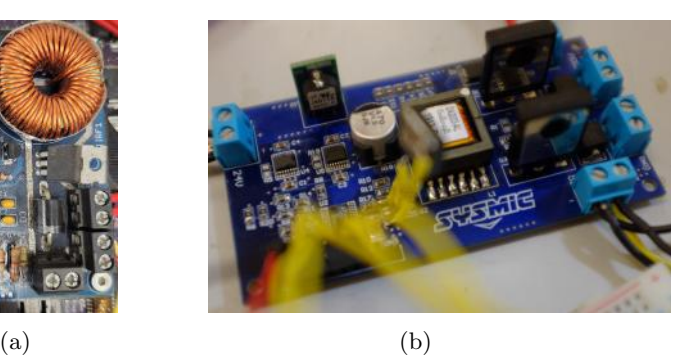
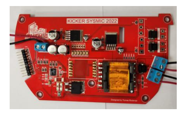
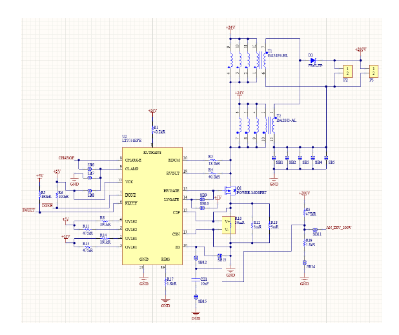
This year we have improved our ball kicking system. The first version of the kicker featured a relatively simple boost circuit that charged two 1200 [uF] capacitors to 120V in about 6 seconds (see Fig. 5a). Given the requirements of the competition, it was necessary to optimize the kicking system, opting to use a high-voltage charge controller for capacitors with built-in regulation, for this we choose the LT3751 integrated circuit (IC) [4]. This particular IC has been used by other teams, such as "MRL Small Size Soccer team [2]" due its fast charging capabilities and easy of integrate. This IC proved to be effective in charging two 1200 [uF] capacitors each at 220V in about 1 second. This led to the development of a new 4 layer PCB with the LT3751 at its core (see Fig. 5b), however the board design induced noise in the sources and generated random system reboots. In this way, the current PCB board for the LT3751 IC was developed (see Fig. 6 for the current board design and Fig. 7 for its schematic), with the following characteristics:
- It incorporates bleeder resistor to lower the voltage level of the capacitors and thus improve kick control.
- Add more filter capacitors to improve voltage stability.
- The relay actuator to deliver energy into kicker solenoid was changed for a high current IGBT with isolated gate.
- The new PCB include the option to test 2 different flyback transformers: the DA2033-AL (5A max in primary coil) and the GA3459-BL (20A max in primary coil). After corresponding tests, we choose to use GA3459-BL because it is 4x times faster charging the capacitors, taking approximately 600 milliseconds.
- The board incorporates multiple solder bridges to test different configuration for the LT3751 IC, like connect FB pin to ground or to a voltage divider in the high voltage side, different voltages for LVgate, different voltages for clamp pin and the option to separate ground for high voltage side.
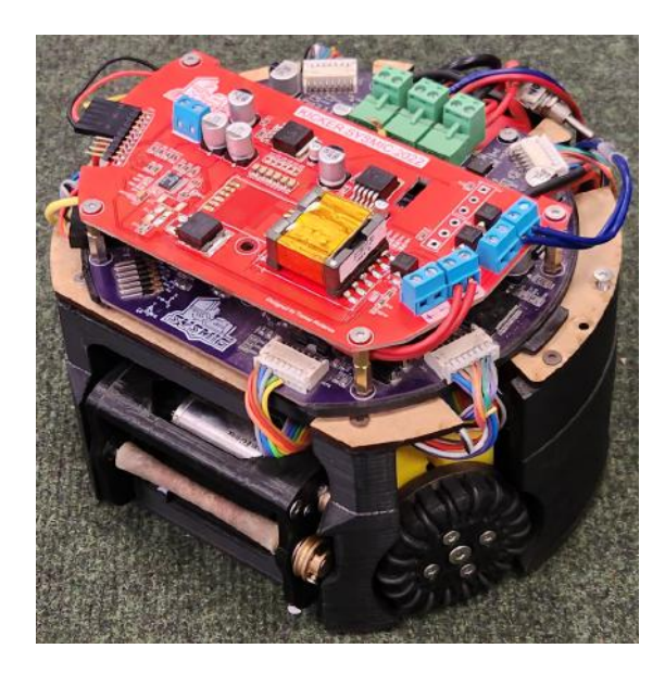
Fig. 8 shows the kicker board mounted on the robot.
Software
Custom client
In the past years, the team relied on a fork of the Robojackets open-source software client to participate in the competition, and to test the mechanic's capabilities and hardware functionality of our robots. Due to an increase of team members majoring in computer science, the creation of a client that fits the characteristics of our robots was a desirable step to develop software more suitable to our needs. Currently, a new version has been developed based on an unfinished project created by former members of our team. The current objective is focused on creating a base framework that allows easy incorporation of future high-level research, thus creating a testing ground for old and new members.
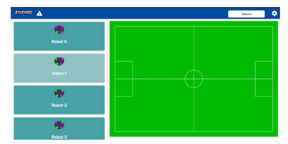
Frontend migration to Tailwind. Our former client's GUI was developed in QT, as reported in our 2019's TDP [8]. The new version of our GUI is based on Electron, a framework for building cross-platform desktop applications using JavaScript, HTML, and CSS. In addition, we are using Tailwind CSS, a CSS framework that allows agile development, based on utility classes that can be easily applied in the HTML code and some development flows to optimize the weight of the CSS code. This new proposal allows us to significantly speed up and modularize the development of our client's GUI and back-end, with modern software tools that are being widely used in the development of different applications. A preview of the current GUI development is shown in Fig. 9. English The biggest advantage of the new GUI is the easy addition of interfaces as new technology is developed by the team. Elements such as the data gathered by the sensor-fusion module, robots battery, signal and other characteristics that could be helpful to visualize to ensure better control of the behavior of our robots in the future matches.
Use of Python as connection between our engine and the view. The first iteration of the new client version was completely developed in JavaScript, which implies that the view and the connection allowed us to show our robots digitally used JavaScript libraries. To achieve this we used dgram, a socket-oriented library that has been deprecated, so eventually, it will be removed from npm (Javascript Software Registry) and could mean important vulnerabilities as well as eventual incompatibilities between the software libraries used.
In response to this issue, we resolved to adopt Python as our intermediate language to link the engine ports with the robots information and the client ports to bind them.
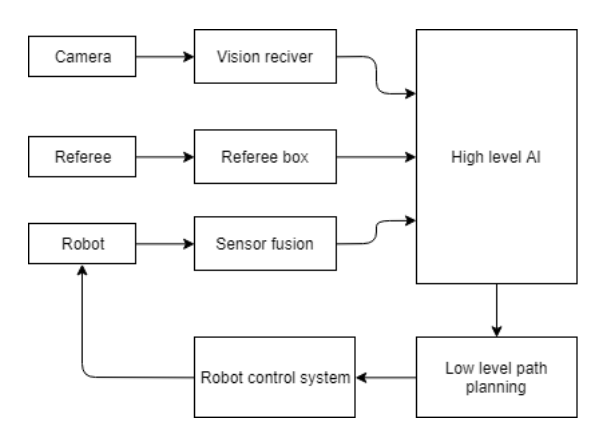
The core aspects of the original vision of the previous version have remained unchanged, with only features already present in the overall structure being updated. This is shown in Fig. 10.
Our team's software section is still gaining strength, and as a result, areas such as high-level AI, sensor-fusion, and self-referee are aspects of the client that we have not yet developed sufficiently to call them substantial progress. Initially, we heavily relied on the software developed by RoboJackets [1], but we found ourselves constantly adapting it to suit our needs. Since we did not write the code, deciphering it was highly unproductive. Hence, we decided to create our own software. Moving forward, we aim to make more robust progress in these areas in future iterations, while relying even less on the software developed by RoboJackets.
New version of the data package
To improve the resolution of the speeds delivered to each robot, we increased the size of the data packet based on the work of ZJUNlict [3] by one byte. This enables us to deliver significant bits that allow better speed control. The data packet used to transmit instructions to the robots is known as the forward data package. The contents of this package are shown in Table 1.
Also, the first byte of the forward packet contains 8 bits. Bit 0 (callback or CB) indicates whether the robot should send a feedback packet back to the client; it is set to 1 to instruct the robot to send packets, and 0 to indicate that it should not send feedback packets. Bit 1 indicates whether the robot should kick the ball; it is set to 1 to instruct the robot to kick, and 0 to indicate that it should not kick. Bits 2 to 4 indicate the dribbler strength, and bits 5 to 7 indicate the robot ID to which the instruction is sent. Bytes 1, 2 and 3 then correspond to the sign and the 6 least significant bits of the vx, v^y and v^θ components of the velocity vector command sent to the robot. Byte 4 contains the 3 most significant bits for v^x and v^y and the 2 most significant bits for vθ, where experience has shown that no extra resolution is required.
We are currently developing a feedback package that will deliver information from the robots back to the client side (see Table 2). Although this package is still in the early stages of development, it already includes data on the dribbler velocity, kicker activation, ball possession, and wheel speed. In addition, the robots are also sending data on local accelerations and yaw angular velocity measured by an integrated inertial measurement unit. This data is intended for use in data logging and an upcoming local position estimation method that will give the robots greater autonomy.
Forward communication protocol
| bit/byte | 7 | 6 | 5 | 4 | 3 | 2 | 1 | 0 |
|---|---|---|---|---|---|---|---|---|
| 0 | Robot ID | Dribbler strength | 1: Shot | CB | ||||
| 1 | ± | Speed vx | ||||||
| 2 | ± | Speed vy | ||||||
| 3 | ± | Speed vθ | ||||||
| 4 | Sig. bits vx | Sig. bits vy | Sig. bits vθ |
Feedback communication protocol
| bit/byte | 7 | 6 | 5 | 4 | 3 | 2 | 1 | 0 |
|---|---|---|---|---|---|---|---|---|
| 0 | Robot ID | Dribbler strength, Shot, Ball | ||||||
| 1 | ± | Wheel speed φ0 | ||||||
| 2 | ± | Wheel speed φ1 | ||||||
| 3 | ± | Wheel speed φ2 | ||||||
| 4 | ± | Wheel speed φ3 | ||||||
| 5 | ± | Front acceleration ax | ||||||
| 6 | ± | Side acceleration ay | ||||||
| 7 | ± | Yaw angular velocity θz | ||||||
| 5 | Sig. bits ax | Sig. bits ay | Sig. bits θz |
References
- Georgia tech robojackets software for the robocup small size league (ssl), https://github.com/RoboJackets/robocup-software
- Amin Ganjali Poudeh, e.a.: MRL extended team description 2019 (2019), https://ssl.robocup.org/team-description-papers/
- Huang, Z., Chen, L., Li, J., Wang, Y., Chen, Z., Wen, L., Gu, J., Hu, P., Xiong, R.: Zjunlict extended team description paper for robocup 2019. CoRR abs/1905.09157 (2019), http://arxiv.org/abs/1905.09157
- Inc, A.D.: LT3751 high voltage capacitor charger controller with regulation (2017), https://www.analog.com/en/products/lt3751.html#product-reference/
- Pablo Reyes, e.a.: Sysmic Robotics - Team Description Paper (2020)
- Ryll, A., Geiger, M., Carstensen, C., Ommer, N.: TIGERs Mannheim - Extended Team Description Paper (2018)
- Ryll, A., Jut, S.: TIGERs Mannheim - Extended Team Description Paper (2020)
- Tomás Rodenas, e.a.: Sysmic Robotics - Team Description Paper (2019)