The A-Team Technical Description Paper 2023
C. Avidano, S. Barnette, M. Barulic, L. Medrano, J. Neiger, R. Osawa, E. Peterson, J. Spall IV, J. Spalten, W. Stuckey, M. Woodward
The A-Team
Abstract "The A-Team" was formed in August of 2021, mostly from Georgia Tech alumni who previously participated on the RoboJackets' RoboCup SSL Team. They seek to solidify their technical skills, inspire the communities in which they are present, and stay connected with friends across the globe. The 2023 competition year is The A-Team's first attempt at qualification. This TDP covers the rationale for the foundational technical decisions made as a 1st year team. Focus was placed on solid foundations: wheel geometry analysis, safe and reliable control and state estimation, and expandable AI and planning infrastructure.
1 Software
The AI software is written in C++ with a ROS2 based middleware and a Vue based UI[1]. The high level architecture will be described with a novel modeling of the multi-robot, multi-role dependency chain in the behavior planning step. Next, the iLQR based trajectory planner with uncertainty modeling is detailed to optimally intercept the ball when capturing and one touch kicking. A delay modeling approach for trajectory planning is also detailed to improve re-planning performance when taking into account the action to measurement delay through SSL-Vision. A new IMM based vision filter is then detailed which will more accurately estimate motion of objects during highly non-linear transition periods.
1.1 High Level Architecture
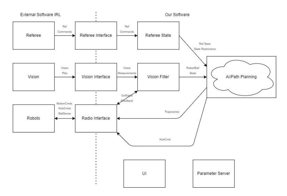
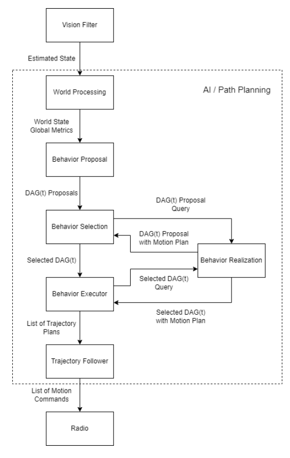
The overall software is split into two main classes of modules: bridge nodes and module nodes. The bridge nodes directly convert the league protobuf (and custom radio packets) into a standard ROS message, and vice versa. The modules nodes run the algorithms. The two main module nodes are the vision filter and AI. The bridge and module nodes with their respective communication are seen in Figure 1. Within the AI module node, a multistage pipeline is run each frame. Firstly, the "world" is prepossessed. This provides a space for high level metrics and multi-frame heuristics to be run reducing wasted CPU resources due to recalculating already calculated values. Next, given the view of the world, the AI proposes multiple different possible behaviors using the DAG(t) structure. Then, each proposed behavior is scored and the best one is selected. This selected behavior is then fully planned and assigned out. Both the behavior proposal stage and the behavior selection stage have access to a behavior realization library. This library fully assigns and generates trajectories for a given plan allowing for high level planning to be done based on the actual motion plans instead of heuristic estimations of these motion plans. The resulting robot-trajectory pairs from the behavior selection stage are fed through to the trajectory follower which serves as the high level pose controller for each robot. Finally, the commands from the trajectory follower are sent directly to the robots. This full setup can be seen in Figure 2.
1.2 DAG(t) Behavior Representation
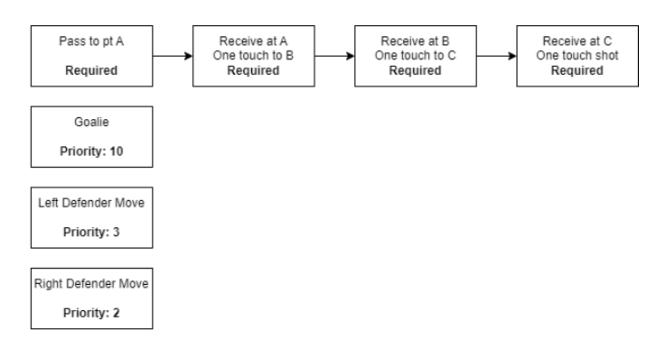
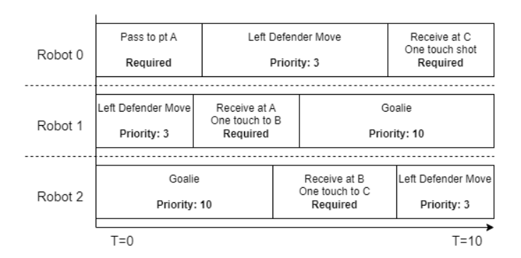
DAG(t) is our novel method to represent the behavior and trajectory planning side of a multi-robot optimization problem in a tractable way. This method
1.3 Motion Planning
Motion planning is highly critical to a successful team. Without a consistent and smooth way to interact with the world, the performance of even the most perfect AI will be highly limited. In this section, two approaches are detailed that will improve our performance in this regard. The first is an iLQR based approach to trajectory planning when interacting with an uncertain ball. The second is a delay compensation method that improves the transition between the old motion plan and a new re-plan.
iLQR Ball state estimation during the initial moments after a kick is highly uncertain. By planning with this uncertainty in mind, it is possible to significantly improve performance, especially in the case of passing and receiving. The high level goal is to maximize the chance that the robot's mouth moves through the ball path within a "reasonable" time frame. The ball uncertainty can be modeled as a time varying PDF representing the ball XY location, with real-time variance parameters coming directly from the vision filter. This can be imagined as a set of samples with different initial conditions as no external forces will act on the ball (besides friction). The robot's mouth can be modeled as a line segment mirroring the location of the physical dribbler where only interactions with a ball from outward facing side are counted as valid. The number of samples moving through this modeled robot's mouth over the entire trajectory can be treated as a cost function for iLQR. By balancing this cost function with a time to complete based component, we can allow iLQR to balance the time to complete the kick/capture as quickly as possible while implicitly modeling the ability to defer the capture to later in time to allow the estimation to stabilize and improve the success rate at kicking/capturing the moving ball.
iLQR will also plan to avoid obstacles as well. By also modeling opponent robot time-varying PDFs as well, we can implicitly model planning around opponents more aggressively over short time periods and less aggressively over long time periods. Over short time periods, the opponent PDFs will be highly centralized around one area spiking the cost of moving through that area. Over long time periods, the PDFs will be highly distributed and will end up with lower costs overall. The specific cost function will be an integration of the weighted intersection of our team's robot shape over the entire plan with the opponent's robot shape distributed over the predicted PDF. The weighting will weight high PDF areas much more significantly than low level behaviors.
The two costs described here are highly non-linear forcing a line search based iLQR implementation with a basic point mass robot model.
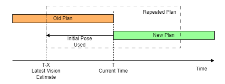
Immutable Duration There is a relatively significant time delay between the action produced by each robot and the software measuring the action. If the camera's measurements are used, the AI will use the robot state from T-X where T is current time and X is the delay. The plan from T-X to T is already sent to the robot and being applied as actions. If the AI replans at this moment, the robot will continue to execute the plan from T-X to T while starting the new trajectory plan at the state from T-X, resulting in the T-X to T segment being re-planned twice. Re-planning at slow speeds results in that X seconds being wasted on unaccounted for motion and slow acceleration. This can be seen in Figure 5.
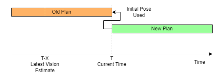
Immutable Duration accounts for this time delay implicitly by locking in the first X seconds of the plan from the last frame. This is done by clipping the last trajectory from T until T + X. The new trajectory is planned starting at state T + X and concatenated onto the clipped trajectory from last frame. The resulting trajectory is used as that robot's trajectory this frame. The overall results during a re-plan can be seen in Figure 6. Note the initial planning state is now based off the previous frame's trajectory and not the vision's estimation. While not ideal, this results in performance requirements from the trajectory follower controller as the AI will make explicit assumptions regarding controller performance.
1.4 Vision Filter
It is critical to have an accurate estimation of the ball to accurately receive the ball and respond to shots. This is a challenging problem due to the ball's highly non-linear switched system when taking into account the ability to be kicked. Our solution was a per-camera Multiple Track Tracker where each track is an Interacting Multiple Model (IMM) filter using a Kalman Filter internally. Each motion model in the IMM filter represents a completely different motion of the ball. The two main motion based models represent the two different friction values associated with the ball during a kick: sliding with a backspin, and rolling along the ground. In addition, there is an explicit model that represents bouncing off a robot with a simplified circle collision geometry. Finally, kicks are represented as short duration modes with a constant velocity at slow, medium, and fast speeds in the direction of the nearest robot heading. During execution, the transition matrix is dynamically varied between all of the states, optimizing out modes where there is no robot near the ball (there cannot be a kick or bounce). Each frame, using the previous state, dynamic transition matrix, and the probability that the sample comes from a distribution acted upon by that specific mode, a probability for each mode can be generated. Based on that probability, a weighted average is used to generate the most likely ball state. By specifically modelling each motion model of the ball, we can tighten the process noise associated with each model allowing for a much more accurate estimation compared to the single model approach. Additionally, we can implicitly detect when kicks and bounces happen based on the mode probability. The motion models, their layperson description, and their time varying probability description are in table 1.
The IMM is also applied to the robot estimation. There are 3 main motion models applied to the robots. The basic motion model is a constant velocity model that is a catch all model. The other two are max acceleration towards the ball, and max acceleration away from the ball. These two models account for robots accelerating towards the ball at the beginning of their motion plan and the deceleration at the end of the plan as they try to interact with the ball. The motion models, their layperson description, and their time varying probability description are in table 2.
Table 1: Ball Motion Models
| Motion Model Name | Description | Activation Period |
|---|---|---|
| Rolling Friction | Default model with rolling friction | All times except when being acted upon |
| Sliding Friction | Sliding friction due to ball backspin right after dribbling kick | Directly after a kick happens |
| Slow/Medium/Fast Kick Constant velocity in direction of heading of nearest robot | Constant probability only when ball is near mouth of opponent robot | Constant probability only when ball is near mouth of opponent robot |
| Bounce | Modified velocity vector based on location ball intersects with robot | High probability when ball is near robot not in mouth |
Table 2: Robot Motion Models
| Motion Model Name | Description | Activation Period |
|---|---|---|
| 0 acceleration | Default model with constant velocity | All times with moderate probability |
| Max acceleration towards ball | Initial acceleration of motion plan towards ball | Low probability always |
| Max acceleration away from ball | Final deceleration of motion plan towards ball | Low probability always |
2 Controls
At the heart of our controller lies a robust model of the robot's kinematics and dynamics. The kinematics model relates the four wheel velocities about their axes to the motion of the robot both in the robot's coordinate frame and the world frame of the field. The kinematics model assumes rolling contact of the four wheels along the tangential wheel path, and thus we can easily compute the body velocities (in either world or robot frame) using the Jacobian of the robot.
To obtain the dynamics model of the robot, we applied the method of Lagrange to derive the robots equations of motion. We chose this method as there are in essence five rigid bodies in motion—the robot chassis, and the four wheels—which each affect the overall robot dynamics. We express our dynamics model in the standard form of the robot equations of motion [2, 3].
3 Platform
3.1 Electrical Architecture
Control Board The control board handles much of the operating logic for the robot, including the processing of commands provided through the radio communication with the host computer, conversion of body-level parameters to wheel-level parameters, kick control, and self-diagnostics. The main microcontroller is an STM32H723, which is based on an ARM Cortex-M7 core. It was chosen for its high pin count, high operating clock frequency, hardware floating point support, and plentiful low-level communication bus peripherals[4].
The control board also has a time-delayed power switch that allows the robot to conduct a safe shutdown process before completely removing power to all of its systems. Immediately upon the switch being throw to the off position, a 3 second countdown begins. If the system has completed its shutdown procedure prior to this time, it can send a signal to immediately cut off the power. This is especially helpful for subsystems such as the SD card writing process to complete its logging and the kicker board to discharge its capacitors prior to power loss.
The STSPIN32F0B drives the each of the four drive motors and the dribbler motor[5]. The chip combines an ARM Cortex-M0 microcontroller with three halfbridge drivers. This integration significantly simplifies the overall architecture, as all of the motor driving logic, timers, and gate driving circuitry are contained within a single chip. These microcontrollers also contain a UART interface that is used to receive velocity commands and transmit back telemetry data.
Kicker Board The kicker board employs a flyback converter to charge a bank of capacitors to 250V while maintaining DC isolation. Since the load-side effectively shorts out the positive side of the capacitor to ground through a low DC resistance solenoid, maintaining DC isolation is a significant factor. The two grounds are, however, still connected such that the solenoid control transistor can be switched without any additional complexity.
Optical Flow Board To aid in relative localization, an optical flow system was implemented. It uses two identical PWM3389DM optical mouse sensors [6]. Each sensor gives a (∆X, ∆Y ) relative to itself in counts per inch. Based on the work covered in [7], two sensors are required for full robot kinematics, individual orientation of the sensors are irrelevant, and they should be placed as far from the center at opposite sides of the robot to maximize the sensor readings. The sensors are read by an STM32F429 [8], which calculates the change in ∆X, ∆Y , ∆θ in the reference frame of the robot based on the work in [9]. This is sent back to the control board for improving velocity estimates.
Radio The team considered multiple radios and multiple radio technologies as candidates for the robot. To aid with selection, the team defined high level requirements, and in order of necessity they are listed below:
- Data transfer rate >50kb/s
- 3 sigma one-way transmission latency <17ms
- Simple and universal local communication interface
- Ability to debug transmission reliability in-situ
- High number of channels or bands to deconflict with other teams
- Data transfer rate >3Mb/s
- Sufficient extensibility to explore league standardization
- RF emission legality in various countries and regions
Specific technologies are highlighted in Figure 7.
| Technology | Rating | Reasoning |
|---|---|---|
| Bluetooth ® | − − − | League Prohibited |
| 2.4GHz Wi-Fi | −− | Heavily discouraged by League |
| 2.4GHz ISM Radio | − | Wi-Fi Interference/Congestion |
| Ultra Wide Band | − | Poor indoor/large venue performance[10][11] |
| 900MHz | + | Need for application layer, low extensibility, international legality |
| 5GHz Wi-Fi | ++ | Cost, costly debug tools |
After considering the mentioned options, the team decided to evaluate 5GHz Wi-Fi. The cost concerns were small compared to purchases like motors, and radio reliability is critical. The team is hoping that advanced 5GHz Wi-Fi algorithms, and high channel availability will allow the robots to leverage RF technology far more sophisticated than raw ISM band radios. Additionally, with TCP/IP or UDP/IP as a provided base, little additional consideration would need to be given to any low level radio communication or radio parameter tuning.
The team selected the Odin-w260 Wi-Fi SoM for evaluation[12]. The cost per module is 45 USD. It has UART and Ethernet RMII interfaces. The fine details of the communication stack (e.g. TCP/IP, UDP) are abstracted away from the user. It supports multicast, making some aspects of network, robot, and conflict discovery much easier. It also has higher level communication options (MQTT, https) which may assist with future security and firmware update ambitions. It was paired with a Unifi Dream Router, which has a typical cost of around 200 USD[13].
The team conducted a reliability and performance assessment. Packet transmission was analyzed round-trip (computer → robot → computer), at a 60Hz rate, for approximately 8 hours (1.6 million packets), in a congested Wi-Fi space. The 5GHz Wi-Fi channel was pinned to one of the 16 channels available globally. During a 5GHz spectrum sweep, 77 other networks were identified in the 5GHz network sweep, so the team considered the RF environment "crowded." Packets not received after 1 second were considered permanently lost. Latency values were calculated by subtracting baud-rate transmission time (at 115200 baud) in an attempt to isolate actual RF transmission delay, and then halving the result. The test microcontroller was a ARM Cortex-M3, with any delays during microcontroller signaling assumed to be negligible.
Our preliminary results are shown in Figure 8 and Figure 9. The test showed we were slightly short of the target 3-sigma latency metric, but given a positive result, strong capabilities for other metrics, and limited time, the team decided to proceed with this technology.
There are clear short comings in the data, notably odd peaks around 2.5ms and 7ms latencies. The host computer tests were run on Windows 10 and Python, which have known benchmarking quality issues. The team will improve and reexplore these tests in the near future, and re-report updated results.
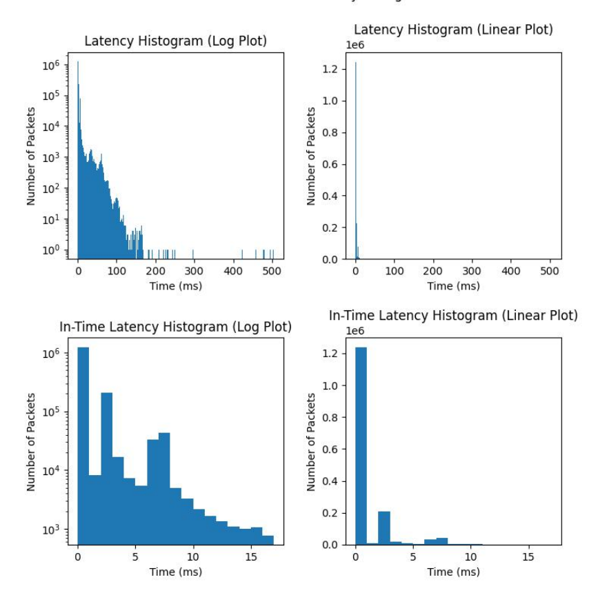
Fig. 9: radio performance summary
| Property | Value |
|---|---|
| Total Packets Sent | 1.6M |
| On-Time Packets | 1561739 (97.61%, z=2.26) |
| Late Packets (latency >17ms) | 38009 (2.376%) |
| Lost Packets (presumed, latency >1s) | 252 (0.0157%) |
| Latency Mean | 1.511ms |
| Latency Std. Dev. | 5.929ms |
3.2 Embedded Rust Firmware
Based on past experiences with subtle run-time stability bugs with embedded C/C++ and FreeRTOS, the team was looking for tools and approaches to mitigate classes of bugs and reduce the surface area for nascent errors. Recent development effort has picked up on Rust for Embedded systems, especially ST Microelectronics Cortex-M systems. Team members have experience with userspace Rust on several professional and personal projects, so the decision was made to use Rust for the STM32H7 primary microcontroller. Below is an empirical and subjective assessment of our experience so far.
As a foreword, the bulk of the broader community uses and develops Embassy[14]. New embedded users, should start there. Due to lack of features, we do not recommend starting with stm32-rs ecosystem[15].
There are key benefits to the Rust ecosystem. Notably, the packaging and build system Cargo can guarantee source equivalent package inputs, readily fetch from online archives, and integrate with tools like defmt (for string processing) and probe-run (for richer debugging). We've found this environment to be significantly nicer and farther ahead than modern C/C++ equivalents. Overall, performance is at or near C code, and binary size is acceptable as long as you can fit a hardware abstraction layer (HAL) equivalent to a C HAL of similar complexity[16]. Additionally, the Rust compiler will enforce at compile time, in safe code, the absence of memory allocation/deallocation bugs, buffer mismanagement bugs, type conversion bugs, and multi-threading bugs[17]. For niche applications such as this, the use of "unsafe" Rust will be necessary, where the compiler cannot enforce safety. In these instances, the compiler tracks the preand post- condition contractual obligations of the function, and assumes correctness. If bugs of the aforementioned classes are found, the designer knows they must be in an unsafe block, greatly narrowing the search for the issue.
As with any new technologies, the team encountered drawbacks as well. It's well established in the Rust community that the learning curve for the language is steep. The team agrees with this assessment, especially when compounded with a very new specification for async on embedded systems. The team paid a noticeable price in development time for the aforementioned benefits. Most of the deep challenges were related to core system setup and bootstrapping a few key items. After core setup, the subjective development experience was excellent. Additionally, there are edge cases in unsupported parts (such as the STM32H7A3) making easy hardware swaps (due to part availability) slightly more challenging.
In summary, at this time we do not recommend the use of embedded Rust by robotics students, unless they want their effort focused on embedded reliability over robotics concepts. The team recommends any group interested in embedded Rust have some previous Rust experience, extensive experience in C, experience porting an embedded standard library such as newlib, knowledge of preemptive scheduler context switching mechanisms, and experience with the low level architecture of the supported chip (Nordic NRF or ST Microelectronics Cortex-M).
3.3 Mechanical Platform
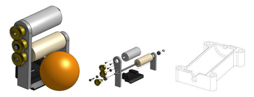
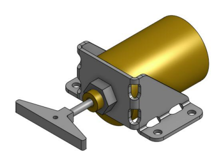
Our robot platform is a simple, modular, and layered design. The lowest layer houses drive modules, the kicker, and the dribbler. The middle layer contains our battery, a Zippy Compact 2700mAh 4S 25C Lipo Pack [18]. The top layer is made of our electronics stack.
We leveraged multiple techniques for manufacturing our robots. Custom aluminum 5052 sheet parts were ordered from SendCutSend, an online laser cutting service. Some light post-processing was required, primarily for holes on the sides of parts. Most of the other custom parts were 3D printed in PLA.
Note that while our prototype electronics are too wide and tall to fit within the legal size constraints for the RoboCup SSL competition, the core parts of our mechanical design do fit within the limits, as shown in Figure 10b. This includes our drive system, kicker, dribbler, and battery compartment. We are working on condensing our prototype electronics into just two PCBs, such that they will fit within the legal competition bounds in time for this year's event.
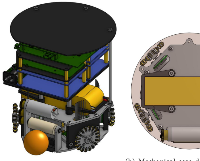
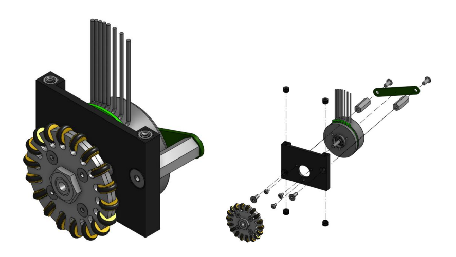
Fig. 12: Motor Specifications
| Properties | Drive Motor | Dribbler Motor |
|---|---|---|
| Model | Nanotec DF45M024053-A2 | Moons ECU22048H24 |
| Rated voltage 24 V | 24 V | |
| Rated speed | 5260 RPM | 17000 RPM |
4 Open Source
Mechanical, electrical, firmware, software, and control and circuit models are published on our GitHub page and licensed for broad use[24].
References
- Esteve Fernandez, Tully Foote, William Woodall, Dirk Thomas ROSCon Chicago. Next-generation ROS: Building on DDS. 2014.
- Richard M. Murray, Zexiang Li, and S. Shankar Sastry. A mathematical introduction to robotic manipulation. 2017.
- Kevin Lynch and Frank Park. Book-Modern Robotics. Number May. 2006.
- ST Microelectronics. STM32H723/733, 2022.
- ST Microelectronics. Advanced single shunt BLDC controller with embedded STM32 MCU, 2022.
- Pixart Imaging Inc. PMW3389DM-T3QU, 2022.
- Mauro Cimino and Prabhakar R. Pagilla. Location of optical mouse sensors on mobile robots for odometry. In 2010 IEEE International Conference on Robotics and Automation, pages 5429–5434, 2010.
- ST Microelectronics. STM32F429/439, 2022.
- A. Bonarini, M. Matteucci, and M. Restelli. A kinematic-independent deadreckoning sensor for indoor mobile robotics. In 2004 IEEE/RSJ International Conference on Intelligent Robots and Systems (IROS) (IEEE Cat. No.04CH37566), volume 4, pages 3750–3755 vol.4, 2004.
- RoboJackets RoboCup SSL Team. RoboJackets 2019 Team Description Paper. Technical report, Georgia Institute of Technology, 2019.
- RoboJackets RoboCup SSL Team. RoboJackets 2020 Team Description Paper. Technical report, Georgia Institute of Technology, 2020.
- u blox. ODIN-W2 series (u-connect) Stand-alone IoT gateway modules with Wi-Fi and Bluetooth, 2022.
- Ubiquiti Unifi. Dream Router, 2022.
- embassy development team. Embassy, 2022.
- stm32-rs devleopment team. stm32-rs, 2022.
- Rushabh Gaherwar. Which is faster: Rust or c? let's find out who is the usain bolt of programming world. 2020.
- Ralf Jung. Understanding and Evolving the Rust Programming Language. PhD thesis, Universität des Saarlandes, 2020.
- HobbyKing. ZIPPY Compact 2700mAh 4S 25C Lipo Pack, 2022.
- Nanotec Electronic U.S. Inc. DF45 BRUSHLESS DC FLAT MOTOR, 2022.
- ams OSRAM AG. AS5047P High-Resolution Position Sensor, 2022.
- MOONS'. ECU22048H24-S101, 2022.
- Smooth-On. VytaFlex™ 30, 2022.
- Magnetic Sensor Systems. Tubular Push Type Solenoid, 2023.
- Members of the A-Team. SSL-A-Team GitHub Organization, 2022.