Triton RCSC 2023 Team Description Paper
Yash Puneet, Rafaella Gomes, Jenny Quach, Rohil Kadekar, Tyler Flar, Kyle Trinh, Syed Islam, Rana Singh, Jason Wong, Kazuma Nagatsuka, Benjamin Liang, Steven Shi, Aditya Parmar, Ali Alabiad, Marisol Soto-Ciriaco, Yichen Yu, Francisco Gutierrez, Joshua Gomez, Peter Li, Zarif Mustahsin, Nathan Kao, Pranav Mehta, Kaylana Nickels, Alejandro Martinez
University of California, San Diego; Institute of Electrical and Electronics Engineers
Abstract This paper describes the design techniques and methodologies used to build autonomous robots meant to compete in the 2023 RoboCup Small Size League (SSL) tournament in Bordeaux, France. The robots have capabilities of path-finding, omni-directional movement, and high instantaneous power flow for kicking. In addition, they have theoretical designs for ball control (dribbling) while in motion. Keywords: Robot, design technique, capacitor charger, algorithm.
1 Introduction
The 2022-2023 season is the team's third attempt at the international competition. Nearly all previous team members graduated from the University of California San Diego in Spring of 2022. As a result, the team became a rookie team, with nearly all members having no prior RoboCup experience. The mechanical design was redone from scratch. The AI has been redesigned as well, utilizing a Behavior Tree instead of a Skill System. Current work focuses on interfacing between the distinct parts of the design.
2 Mechanical Design
2.1 Materials and Prototyping Technology
As sturdiness and weight are major factors for the robots due to rapid movements being required as well as being able to keep up with the ball and opposing team robots, the choice of material is a major aspect of the mechanical design.
For our initial prototypes, we are using 3D Printing with PLA for the most part to so we can have a functional chassis for testing other components without having to first spend time trying to perfect the use of different technologies/materials. We hope to work with different materials for different parts of our final robot to account for the various needs of these parts. The current plan is as follows though this may change after we experiment with these materials:
- Laser cut metal (probably aluminium or steel) base-plates for sturdiness and to keep the heaviest part of the robot at the bottom for added stability
- Laser cut wood for internal parts so it is quick to create and it doesn't need to be very sturdy and resitant to wear and tear
- 3D Printed PLA or Resin for more intericate parts such as fasteners or cable channels
- Carbon-fibre for most of the baseplates and major supports
- Vacuum Formed plastic for the extrenal shell for weight considerations. Sturdiness will be provided by the internal structure and supports.
2.2 Drive Train
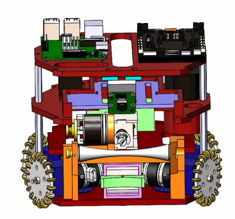
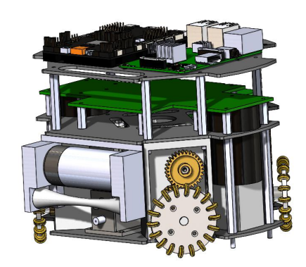
The robot uses four omni-directional wheels oriented at 90 degrees from each other for all wheels. This angle inclination allowed us to model standardised equations for all axes of motion and simplify the robot's movement commands. However, this reduced the space we have for the dribbler near the front. We are currently experimenting with dribbler designs to account for this limited space. We may increase the angle for the front wheels slightly and account for this in our omni-wheel motion models if we require more room for effective dribbler and kicker mechanisms in the future. For the motors, we are using DJI Robomaster M2006 P36 Brush-less motors paired with the same manufacturer's C610 Electronic Speed Controllers (ESCs). We chose these since we are using the DJI Robomaster Type A Development Board to control our actuators and using parts from the same manufacturer would eliminate any compatibility issues.
2.3 Kicker
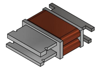
The solenoid construction will remain the same as last year for the same reasons, maximising space efficiency. Thus, we will continue to use the TIGERs Mannheim's stadium-shaped solenoid design.
Provided that we have all other functionality working in time, we may experiment with new solenoid designs for faster or more complex kicking motions.
2.4 CAD Design
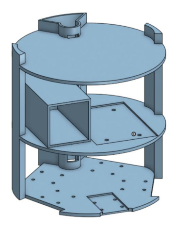
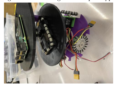
The CAD design team has created empty space for cable management of the wires to be run through the lowest layers to upper.In attempts to create stability between the layers two vertical spars connect at the edges are seen. A space for the battery, and slightly sunken areas to embed electronics onto the board to maintain position were added. The base is expected to undergo changes to account for the solenoid-dribbler.
3 Electronics
3.1 Kicker Board
The Kicker Board mechanics are expected to remain the same for this year's construction though we plan on changing the way it is implemented. The basic mechanism of our kicker board revolved around the charging of high power capacitors and rapidly discharging them through a solenoid to achieve a quick extension and retraction of the plunger. We are experimenting with using high power boost converters to charge capacitors in a safer way but this idea is still in its prototyping stage. We will be testing both strategies (the previous design with charging ICs and the one we are experimenting with using boost converters) to compare performance before deciding on the best way forward. Additionally, we are theoretically designing the possibility of a moving kicker mechanism to allow angled kicks using a servo motor rather than having to reorient the entire robot.
4 Embedded Systems
Embedded systems are responsible for the integration of hardware and software on the robots. Our goal is to establish a robust network of communication between the physical movers of the system, or actuators, and the software-coupled sensors to exchange data efficiently.
For communication, while Universal Serial Bus (USB) was used by the teams in the previous years, this time we are working with UART to allow the Raspberry Pi 4 to send signals to the STM32 microcontroller. This year's team members are more familiar with UART, since it has a plethora of documentation available and is easy to use for one way data transfer from the Pi to STM32.
4.1 Current Experiments with Control Systems
As stated in projected improvement goals by previous year's team, we are working on updating our embedded systems for better performance during teh competition.
We are working on defining a set of system specifications for the robot that translate to requirements for PID control. This primarily involves calculating the percentage overshoot of our robot's motion as compared to the expected movement range based on the given command, settling time for these inaccuracies to be bound by acceptable margins, and maximum response to a unit disturbance to account for error tolerance. We plan on implementing either hardware or software PID, or a combination of both, in order to make our robots more adaptive to errors that might occur in converting software simulations to physical movements.
5 Calculations for Successful Task Execution
One of the most important calculations to factor in is the rolling of a ball. This is important as figuring out ideal angles to push the ball at can help with robot design and help the robot be able to control a ball better.
A variable we need to account for in order to have ideal rolling is the friction from the floor. The best way to avoid friction as much as possible is to push it with as small of an angle as possible (measuring from the horizontal), but not entirely at zero as then the ball would be harder to control and we would have no resistance.
Friction is calculated with this equation:
$$F_f = \mu * N$$
In this case, N or normal force is equal to the weight of the ball itself plus the vertical component of the force applied (F), turning the equation into:
$$F_f = \mu * (sin(\theta) + W_{ball})$$
The closer the angle gets to zero, the less friction we add from the component that pushes the ball around. If we pushed the ball from underneath (upwards angle), it would reduce friction by lowering the vertical component caused by the weight of the ball, but makes the ball harder to control, meaning that the most ideal angle to push the ball is an angle a bit more than zero from the horizontal.
Control of the ball is affected by Newton's 1st Law. With Newton's 1st law, we know that if the ball is moving, it will continue moving unless another force is added, hence why we have a slight vertical downwards from the robot pushing the ball.
6 Software
6.1 General Setup
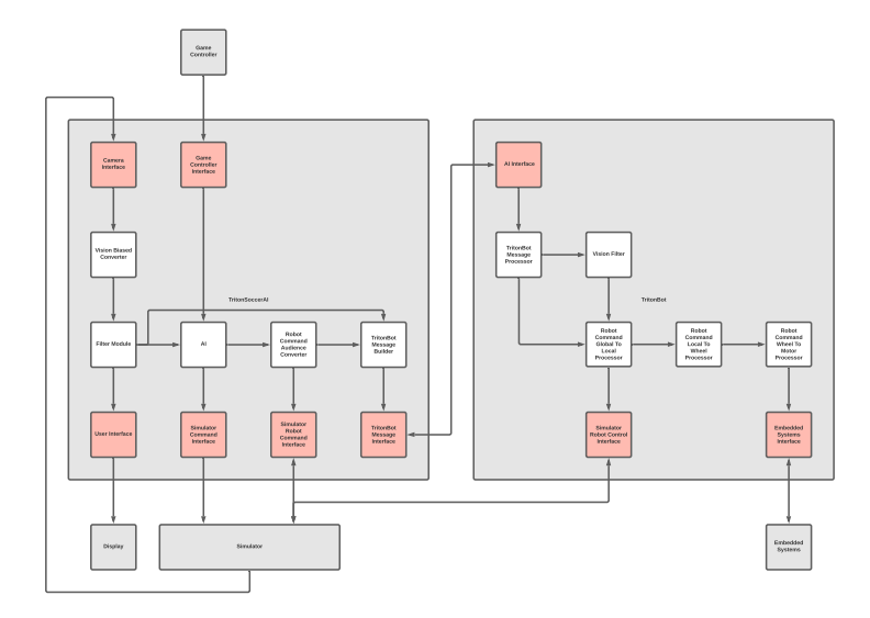
The general software setup continues to be the same as last year's, as illustrated in Figure 6. Both TritonSoccerAI and TritonBot use a simplified Publisher-Subscriber system for convenient inter-thread communications, facilitated via RabbitMQ and User Datagram Protocol (UDP).
6.2 TritonSoccerAI Software (Java)
Last year, our AI ran on what we called a "Skill System." Each skill was composed of sub-skills, which were composed of sub-sub-skills, etc. Though skills could run concurrently, all sub-skills of a given skill had to finish running in order for a given skill to finish running. As a result, this AI design proved too slow. Some skills, which took longer to run, would often prevent the AI from making decisions on skills that had already terminated.
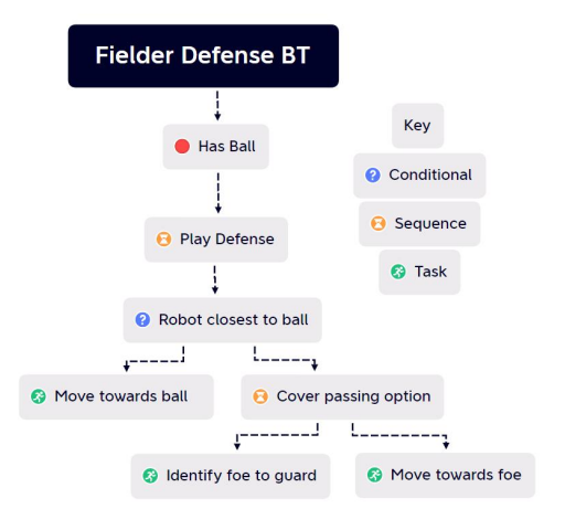
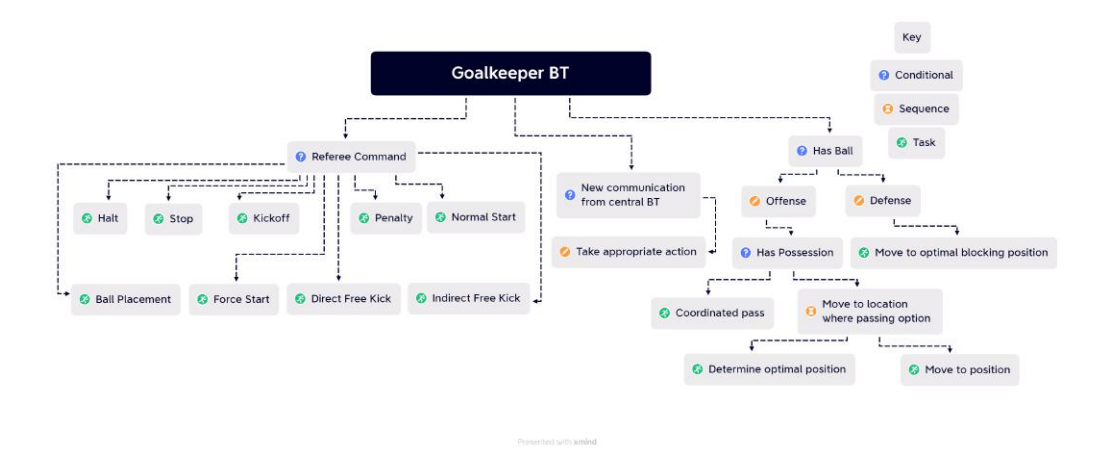
We decided to redesign our AI completely, switching to a Behavior Tree based system. A Behavior Tree is a Tree of hierarchical nodes, with the nodes at the ends, called leaves, executing commands. A Behavior Tree is iterable and customizable. But most importantly, with this new system, a given node may terminate without terminating or even running all its child nodes, which results in a much faster AI.
We will expand on this particular improvement in section 5.4
6.3 TritonBot Software (Python)
TritonBot will run on the Raspberry pi, which is installed in every robot and serve as a middle communicator to trasnmit the commands from TritonSoccerAI to embedded system. To receive the commands from TritonSoccerAI, each robot acts as its own UDP server, receiving commands from the TritonSoccerAI client. The commands received from TritonSoccerAI are vectors in global space that get converted from global space to local space to wheel space by TritonBot's processing modules. Each processing module connects to each other over RabbitMQ which takes the role of an intermediate buffer.
In competition set up, TritonBot now sends motor commands to the embedded systems Robomaster through UART instead of USB, as was the case last year. This mode of communication involves the use of two channels, namely TX and RX, to transmit and receive signals. Specifically, the TX pin transmits signals to the peripheral while the RX pin receives signals. We opted for this mode of communication due to its simplicity in terms of connections, as it requires only a few pins and a single wire. Additionally, since we only intend for the Raspberry Pi to transmit data and for the RoboMaster to receive it, the simplicity of the communication method was deemed sufficient. Despite being an older form of communication, we found available code to establish and facilitate communication between the boards.
6.4 Behavior Tree
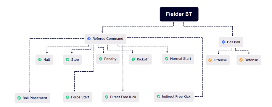
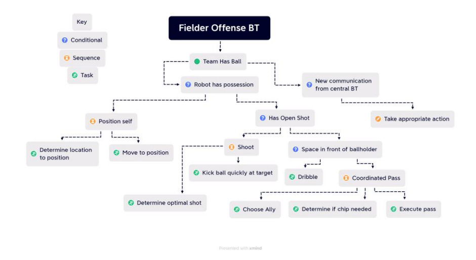
Currently, the AI utilizes a behavior tree to make decisions, according to the diagrams shown. Nodes may be utilized by parent nodes to allow for larger tasks to be completed by breaking down the large task into smaller sub-tasks. In our model, each robot runs its own behavior tree independently, thereby giving each robot the ability to make decisions about its own actions. Each fielder robot runs identical fielder trees while the the goalkeeping robot runs a goalkeeper tree. To assist in coordinated actions (eg. passing), a central coordinator is utilized to send messages to all behavior trees. Types of nodes include composite nodes that define behavior for a branch, conditional nodes that check if a particular condition is satisfied, service nodes that run at a defined frequency, and task nodes that perform distinct low-level tasks. The sub-nodes of a given node must finish execution in order for the higher level node to finish execution. Multiple service nodes can run concurrently but multiple task nodes may not run concurrently.
6.5 Future Goals
Future Modules Before actual competition, both TritonSoccerAI and TritonBot need additional modules. TritonSoccerAI requires a module to receive SSL-Game-Controller messages. TritonBot needs modules to process local commands to wheel commands, wheel commands to motor commands, and a module to send these motor commands to the embedded system.
Future Pathfinding and Noise Filtration Improvements The current pathfinding algorithm functions well for simpler situations but needs improvement in finding the most optimal path in a fast-paced environment where many variables are rapidly changing. One of the main scenarios that needs improvement, for example, is the scenario where the path to the target location is completely free from obstacles. In the past, we have integrated Jump Point Search (JPS) in our pathfinding, which has yielded very optimal results, and we hope to build on that again this year.
JPS is an optimal algorithm for finding a path when there are few obstacles. This algorithm aims to jump-ahead in a particular direction as far as possible, thereby skipping many nodes. The goal is to expand until you reach a node of interest, which could be a things such as a "forced neighbor" (e.g. an obstacle nearby that breaks the assumption that heading further in that direction is most optimal), an edge, or the target node. That node is then added to the open set and then the scenario is re-evaluated. Just like with A*, the paths generated from JPS can be post-smoothed by checking line-of-sight with the other nodes further down in the path.
Additionally, the prediction of the field is rather simple at the moment. All obstacles are currently approximated with circles whereas other shapes can be utilized for more precise and accurate representations of obstacles. For example, ellipses would be utilized to represent moving robots, with the velocity of the robot determining the dimensions of the ellipse. In addition, the accelerations of the objects have not been accounted for yet due to significant amounts of noise. The accuracy of both the velocity and acceleration can be increased by improving noise filtration, which we aim to do by using the Extended Kalman Filter algorithm. The EKF algorithm operates by updating its predictions based on measurements and then adjusting, providing a more accurate estimate of the velocity and acceleration of the objects and reducing the effect of measurement noise. This will be especially important when integrating the Triton Bots in real life since there will certainly be a great deal of noise.
Future TritonSoccerAI Improvements During the course of the next few months, we expect many changes will be made to the initial designs of the behavior trees based on the results of testing and simulated gameplay. The algorithm to identify the optimal shot can be improved as well as the similar algorithm to identify the optimal pass. In particular, the adding of the capability for a robot to make a through pass (forward pass into a space 1-3 meters in front of the targeted pass reciever) is a significant priority in order for robots to not be limited to straight-line passes to one another. Positioning when on offense will need significant improvements as positioning decisions will be made individually by each robot as opposed to a centralized source, like in previous years.
Future TritonBot Improvements We are planning on making one UDP server for TritonBot and TritonSoccerAI to connect to as clients due to there currently being only one-way communication from TritonSoccerAI to TritonBot. This would allow for better consistent status updates from TritonBot for situations where a robot was unable to complete a command or is currently stuck processing a different command.
We also plan on phasing RabbitMQ out as it provides very little benefit compared to the amount of overhead it takes to set up. Using a Python library buffer or file system may be more effective for our purposes.
7 Acknowledgements
We would not have been able to make so much progress without the RoboCup community for the extensive information put online in terms of EDTP, TDPs and GitHub repositories. We would also like to thank TIGERS Mannheim, for their extensive contributions to the RoboCup community and being advocates of open source development. Finally, a big thanks to Nicolai Ommer for his responsiveness and lending of the field camera.
We would also like to thank the UC San Diego IEEE Chapter for their support, guidance, and funding.
A special thanks is due to Professor Amy Eguchi with helping us establish contact with the RoboCup organization and helping the team grow its connections.
Special thanks to the UCSD Makerspace and the Director, David Lesser, for providing our team with the tools and space to build our prototype
Table 1: Robot Specification Table
| Robot Component | Details |
|---|---|
| Embedded Computer | Broadcom BCM2711 Cortex-A72 (ARM v8) 64-bit SoC @ 1.5GHz (Embedded in Raspberry Pi 4B) |
| Embedded Microcontroller | STM32F427IIH6 Cortex-M4 (ARM) 32-bit C @ 180 MHz (Embedded in DJI RoboMaster Development Board Type A [abbrev. as RM]) |
| IMU System (9DOF) | MPU6500 6DOF IMU (Embedded in RM), IST8310 3DOF Magnetometer (Embedded in RM) |
| Proximity Sensor | ST VL53L1X ToF (Not included in the current prototype, but will appear in a future upgrade to detect ball-holding status) |
| Communication | WiFi between standard home router and our PC |
| Main Motors | DJI M2006 Motor with built-in encoders, Max 500 rpm, Max 44W, 416rpm at 1 Nm, @24V |
| Gear Ratio | 3.33, wheel speed up to 1385.28 rpm |
| ESCs | DJI C610 32-bit FOC ESC (interfaced with CAN BUS), @24V, @Max 10A |
| Wheels | GTF 50mm Omni Wheel |
| Dribbler Motor & ESC | T-MOTOR MT2212-13 980KV Brushless Motor (current prototype), XING-E 2207 1800KV Brushless Motor (future upgrade), ICQUANZX ESC BLHeli S 6s 35A |
| Kicker Circuit | LT3751 Capacitor Charger Controller IC, GA3459-BL Flyback Transformer (turn ratio 1:10), FDS2582 NMOS, ES3J, IKB40N65ES5, SMBJ13CA, 2700 Capacitor, LTC4231, LTC2955, @22.2v operating voltage, boost to 130V in 272 ms |
| Power Supply | Ovonic 1300mAh 22.2V 6S 100C |
References
- Andre Ryll, S.J.: Tigers mannheim (2020)
- Ryll, A., Ommer, N., Geiger, M., Jauer, M., Theis, J.: Tigers mannheim (2019)