2023 Team Description Paper: UBC Thunderbots
Aakaash Senthilkumar, Amtoj Sidhu, Arun Balamurali, Dannon Sturn, David Antoniuk, Derek To, Fatima Muhstaq, Francesca Crema, Henry Bryant, Henry Rovner, Jonathan Lew, Kenny Wakaba, Nima Zareian, Omri Levy, Raiaan Khan, Rocky Cao, Ryan Nedjabat, Tara Kong, Shayan Ajmal, Sylvia Ly, Yichen Zhou
The University of British Columbia
http://www.ubcthunderbots.ca · https://github.com/UBC-Thunderbots/Software
Abstract This paper details the design improvements UBC Thunderbots has made in preparation for RoboCup 2023 in Bordeaux, France. The primary goal was to investigate and resolve issues encountered in the newest generation of robots used at RoboCup 2022. The secondary goal was to redesign and create new systems in these robots for improved durability, ease of use, and gameplay. We additionally describe the wideranging software architecture improvements to robot software, motion planning, strategy and planning, simulation, and visualization that were implemented since RoboCup 2021.
1 Introduction
UBC Thunderbots is an interdisciplinary team of undergraduate students at the University of British Columbia. Established in 2006, it pursued its first competitive initiative within the Small Size League at RoboCup 2009. The team has consecutively competed in RoboCup from 2009 to 2022 and is currently seeking qualification for RoboCup 2023. Over the past year, the team has made significant developments for its newest generation of autonomous soccer-playing robots. This paper outlines UBC Thunderbots' progress in improving the mechanical, electrical, and software systems in these robots to compete in RoboCup 2023.
2 Mechanical
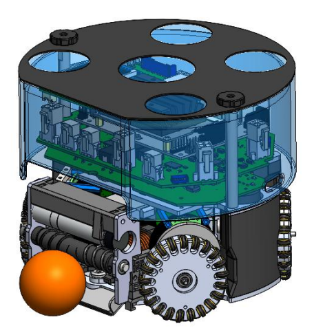
For 2022/23, our mechanical team has focused on making improvements to our previous robot design, including upgrades to the chipper, dribbler, and Geneva drive kicker systems. We have also been improving our robots' robustness and manufacturability by optimizing several component designs detailed in the sections below. Our current 2023 CAD model is shown below in Figure 2.1.
2.1 Dribbler Assembly
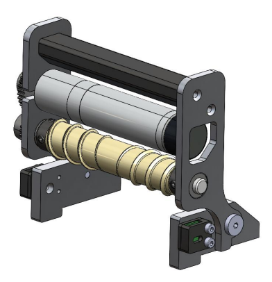
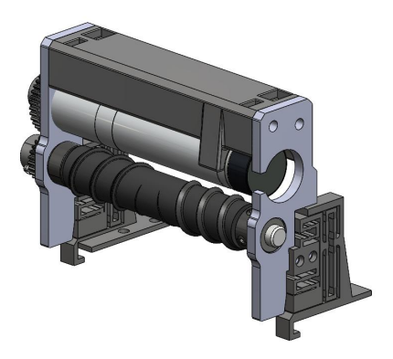
Our previous dribbler assembly used a pivoting system with damping foam inserted on the upper-rear end of the structure [1]. Problems included inconsistent damping, "drooping" of the assembly, insecure fastener threading, and low rigidity. This year, several design changes were made to improve our dribbler.
2.1.1 Structure
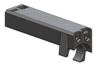
Our previous dribbler assembly consisted of a 3D printed crossbar that screwed on to each dribbler side-plate. However, fastening between these parts was inconsistent and screw holes dethreaded easily, resulting in the assembly losing its rigidity. We 3D printed a new bar with captive nuts, as shown in Figure 2.3. This resulted in a solid structure and increased robustness of threaded connections. Furthermore, given that the dribbler motor is only attached to the assembly on one end, we incorporated a clamping structure into the crossbar design to prevent it from drooping. This single integrated component can be easily 3D-printed with no support required.
2.1.2 Damping
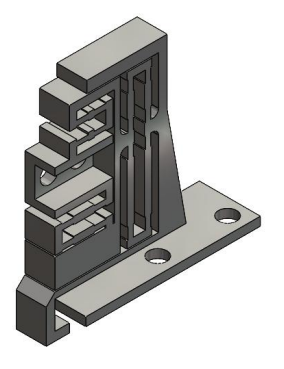
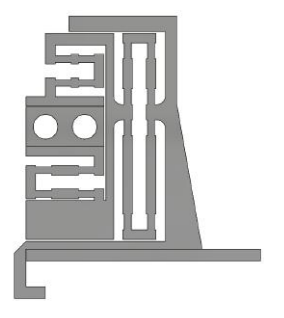
Successful damping allows our robots to have consistent and efficient ball control. Our previous assembly used foam which resulted in inconsistent and poor damping between robots. This year, we explored using compliant mechanisms to create a compact and easily tunable damper. Successful dampers, such as Tigers' [2] and Zjunlict's [3], use a bi-directional damping system, where our previous rotational damper was limited to one rotational degree of freedom. We developed flexures to both damp and attach the dribbler assembly to the robot, providing freedom of movement in multiple directions simultaneously.
2.1.2.1 Compliant Mechanism Design
Compliant mechanisms offer flexibility when optimizing. By adjusting the design parameters, we can achieve a variety of behaviours. Our flexures are 3D-printed with PETG; the material is slightly viscoelastic, providing a subtle amount of damping while also remaining durable and tough. To model our damping system, we analyzed the general ordinary differential equation for a simple mass spring system:
$$m\ddot{x} + c\dot{x} + kx = F(t)$$
By increasing the flexibility of the flexures (decreasing k), we significantly reduced oscillations when the ball makes contact with the roller. Furthermore, by giving the entire dribbler assembly the freedom of movement in the forward direction, we can prolong the contact period between the ball and roller during reverse movement, and therefore maintain the frictional force between the two surfaces.
2.1.3 Roller
This year, we focused on improving our manufacturing methods of our dribbler rollers. Our dribbler rollers are cast in 3D printed molds with a 1:1 polyurethane mix of Shore 50A hardness. Our previous mold design lacked rigidity and leaked easily. This year, we created an outer shell for the mold assembly, preventing movement in the horizontal plane as well as blocking the previously open base. The top part of the mold has also been extended to restrict the shaft from moving as much during molding.
2.2 Chipper
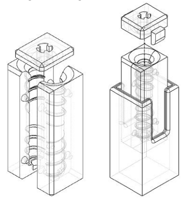
Our main objective was to improve upon our 2021/22 chipper design and create a more consistent and powerful chipper [1]. A main issue was significant deformation occurring on the main chip plate after repetitive chipping. We hypothesize this is due to inconsistent bends from the press brake and the softness of the steel used to make the chipper. As the chipper continued to warp, it would often get stuck at its fully actuated position without returning to its rest position. The proposed chipper material, cold-rolled steel, has a higher strength in comparison to the previous year's material, hot-rolled steel. We also thickened the chip plate, which along with the new material, should decrease deformation. Moreover, new bending jigs and procedures were designed in order to have consistent bends of the chipper arms. The chipper arms were redesigned from square plunger posts in chipper arm slots for brass rollers to reduce friction and the chances of the chipper getting stuck at its fully actuated position. Figure 2.6 shows the new chipper design, excluding the springs.
We also increased the angle between the chip plate and the ground. In theory this would allow for the chipper to chip the ball higher and help with the dribbling of the ball, as the contact point between the ball and the plate would be lowered. In our previous chipper system, the angle between the plate and the ground was 30 degrees, and our new prototype has an angle of 40 degrees. Physical testing will be performed to determine the optimal plate angle.
2.3 Geneva Drive and Kicker
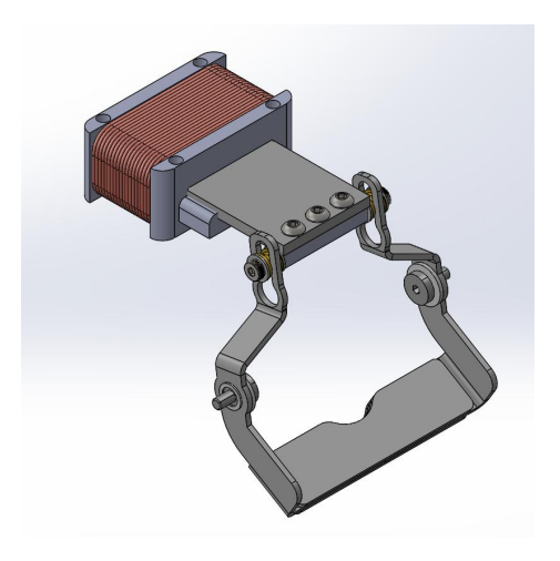
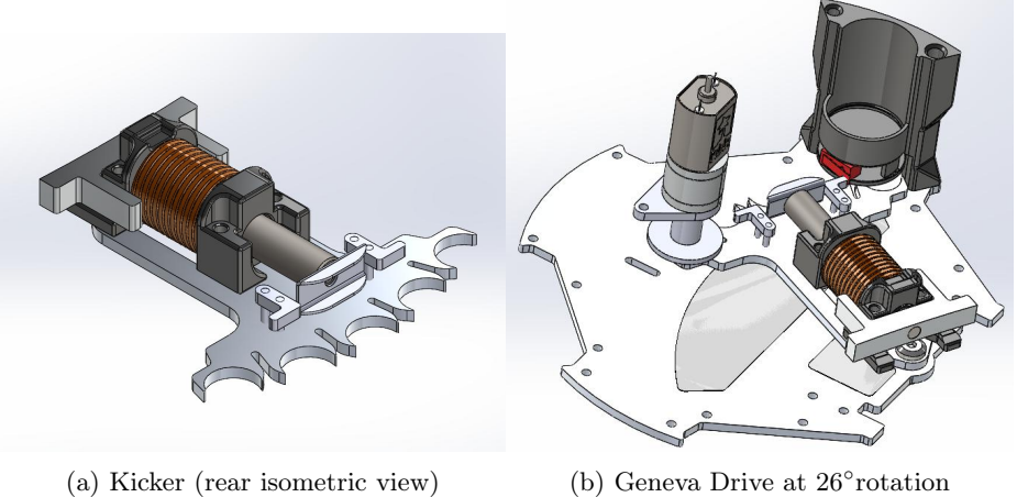
In 2019 we looked to incorporate a Geneva Drive in our design to allow our robots to complete angled or curved shots as well as passes, with the aim to make our gameplay more difficult for opponents to react to. We continued to improve this design from 2020-2021 where we used a Geneva Drive to rotate in and out of a kicker mount in varying settings, allowing the kicker to hit the ball at -26°, -13°, 0°, 13°, and 26°. The Geneva Plate design can be seen in Figure 2.7a below.
Currently, an encoder is in place to track the number of rotations the motor has completed, but this limited the encoders to only give a relative position to an arbitrary datum which would be lost and redefined each time a robot is turned off and on. Thus, an offset from the true position frequently occurs, causing the Geneva Drive to attempt rotation beyond its furthest angle. This year, a limit switch (shown in red in Figure 2.7b) was introduced below the capacitor holders. Once the Geneva Drive has reached its end position, the switch is triggered, which both stops the Geneva Drive and sets a home reference for the encoders, thus preventing over-rotation.
3 Electrical
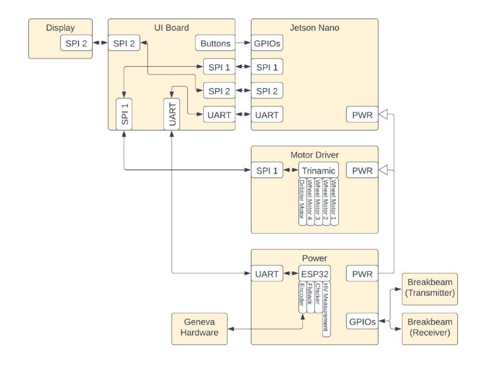
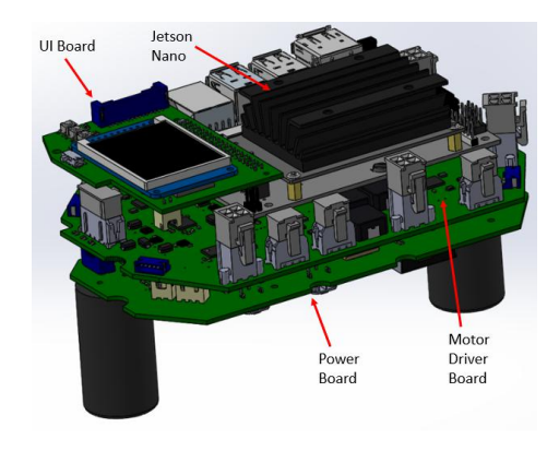
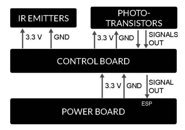
Year marks the continuation of our redesign implemented in 2021-2022 [1]. A notable change from the 2021-2022 electrical system is the introduction of Reciever, Transmitter, and Control breakbeam boards to avoid failure of offthe-shelf components, which was experienced at RoboCup 2022. Additionally, we have made improvements to the Power board, UI board, and Motor Driver board. The electrical system diagram is shown in Figure 3.1, with the stackup shown in Figure 3.2.
3.1 Electrical System Overview
This year marks the continuation of our redesign implemented in 2021-2022 [1]. A notable change from the 2021-2022 electrical system is the introduction of Reciever, Transmitter, and Control breakbeam boards to avoid failure of offthe-shelf components, which was experienced at RoboCup 2022. Additionally, we have made improvements to the Power board, UI board, and Motor Driver board. The electrical system diagram is shown in Figure 3.1, with the stackup shown in Figure 3.2.
3.2 Power Board
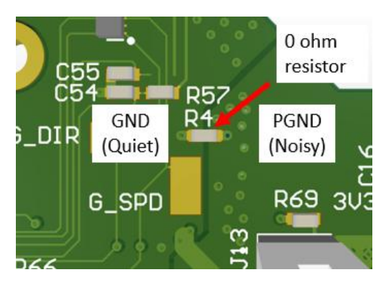
Since 2021, our power board has housed both the chipping and kicking circuitry. With this design, we observed that when our robot kicked, other electronic modules such as the Jetson Nano and motor driver board would reset. We believe that this is due to the transients induced by switching the solenoid at high voltage, and have measured GND bounce on the voltage rails during a kick. To address this issue, in 2022 we tied the ground of the high voltage side to the ground of the low voltage side and split the ground planes into one quiet ground (GND) and one noisy ground (PGND). We then connected these grounds through a 0 ohm resistor. We theorized that the quiet GND would be isolated enough from the noisy PGND to prevent this behavior, but it still occurred. We then decided to galvanically isolate the high voltage section from the low voltage section of the board. This is intended to reduce the effect of the transient noise generated by the kicking action.
3.2.1 Galvanic Isolation
To have galvanic isolation, we need to isolate the secondary side of our flyback converter from the primary side, which is relatively easy due to the built-in transformer. We also have to isolate the gate driver from the gate of the IGBT, which will reside in the high voltage section. Due to a part shortage, it is difficult to find inductive gate drivers that only require a single power supply on the input side, so we are implementing gate transformers to isolate the IGBT gate from the gate driver.
3.2.2 Buzzer Alert Feature
Since it is a safety hazard to leave a robot powered off with its batteries plugged in, we are adding a buzzer circuit to audibly alert the user in this case. The buzzer circuit includes an NPN Mosfet as a switch, a RC circuit to add a short delay, and a diode to regulate the buzzer voltage.
3.3 Motor Driver Board
The newest version of the motor driver board (V5.3) includes fixes first tested at RoboCup 2022, such as minor passive component changes and more substantial design changes which will improve the operation of the motor driver board. Some of these minor design changes are currently being implemented, such as changing the current sense resistors for a higher dribbler motor current limit, and modifying the snubber circuit to avoid ICs heating from a parasitic load. Some of the important new changes being implemented are outlined as follows:
- Improving SPI layout to improve communication across the board.
- Removing the isolated ground (the TMC6100 has a connected ground).
- Adding differential pair routing for the current sense traces to minimize noise.
3.4 User Interface Board
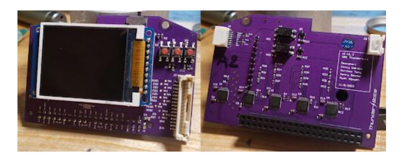
The user interface board (UI) was first introduced in our 2022 TDP as both a breakout for the Jetson Nano pins and to support a screen for users to read and control a robot's status [1]. The primary objective of UI V1.3 is to address the problems found in its previous version, including a flawed interface switch (rotary encoder) due to an unexpected voltage divider from an internal pullup, and an insufficient drive strength on the Jetson GPIO pins which degraded the integrity of the signals and also eliminated the possibility of using RC filters. To address these problems, we:
- Replaced the rotary encoder with push buttons to simplify its firmware.
- Added buffers for better drive strength as well as slight improvement in its signal to noise ratio (SNR).
3.5 Breakbeam Board
Motivation In our 2021/22 design, we often found there to be issues with the breakbeam system's durability and alignment. We plan to resolve this issue by implementing our own custom circuit boards for the breakbeam system. We also plan on adding redundancy to our design by including a second emitter/receiver pair in case the first IR emitter or receiver is damaged or becomes inoperable. Separate PCBs for the breakbeam system also adds a degree of modularity, allowing for alternate systems to be implemented if we decide to modify our current IR emitter/receiver pair. Furthermore, on the new board we will include a status LED to provide visual verification of the breakbeam status.
3.6 Kick Speed Tester
We developed a "kick speed tester" to calibrate the kicking speed of each robot. The tester accomplishes this by utilizing two pairs of sensors and the known distance to determine the approximate speed of the ball. The Kick Speed tester has wrapped up development and is undergoing final testing in order to implement it at RoboCup 2023.
3.7 Power Board Automated Tests
We are currently developing automated tests for each of our circuit boards, which enable users to easily test the robots circuit boards. This will speed up debugging since users will not need to understand board specifics, and can test each board in an isolated setting. Automated tests will run through a series of checks which are unique to the board we are testing. For ease of use, we plan to include a simple GUI to instruct the operator on how to correctly set up the board for each test. We are using an external ESP32 microcontroller to simulate sending and receiving signals for whichever board is being tested. Automated tests for the power board are currently being implemented and will serve as a reference for developing automated tests for the remainder of our boards. The tests will check the behavior of the isolators, voltage monitor, encoders, and HV generation.
4 Software
All software & firmware is open-source, and is available from our git repository: https://github.com/UBC-Thunderbots/Software.
4.1 New Motion Planning Stackup
Previous Motion Planning Architecture As outlined in our 2020 TDP [4], our motion planning architecture consisted of a path planner and a trajectory planner running on the AI computer. The team previously used a refined version of a grid-based planner A*, called Theta*, to find the path that minimizes total direction changes and total path length using the Euclidean distance to the destination as a heuristic during search. Our implementation represented the Division B field using a grid, where each grid cell could be marked as blocked, or unblocked depending on if an obstacle overlapped it. To account for moving robots as obstacles, these objects were expanded in the grid by an experimentally-determined factor to reduce the likelihood of high-speed collisions through delays.
4.1.1 Motivation
While this motion planning architecture was effective during Division B games, we encountered a number of issues that were challenging to solve with the previous architecture. Outlined are the issues we aimed to solve:
- In the worst-case scenario, with a resolution of 9 cm for the grid cells, Theta* would search through the entire 100 × 67 grid space for a Division B field.
- If surrounding grid cells of any two endpoints were blocked, then our implementation of the neighbouring cell search could search the entire grid space, taking up to 500 ms for all six robots.
- Our previous implementation did not leverage the nature of path planning in a relatively sparse field, as majority of paths were trivial straight line paths. The implementation checked line of sight between the current position and the previous position, causing trivial paths that span the field to be more computationally expensive than required.
- Additionally, an unrelated issue to motion planning was that under our Skills, Tactics and Plays (STP) architecture, our robots were prone to oscillating between robot-to-tactic assignments at every AI tick. It was theorized that accounting for the actual path length around obstacles when assigning the robot to tactics would reduce these oscillations and improve overall gameplay stability, but the previously outlined performance issues prevented this possible improvement, considering this required computing paths for n² robots, rather than n.
For this reason, the team chose to pursue other architectural solutions that could address the noted performance issues while also enhancing our motion planning capabilities.
4.1.2 Proposed Architecture
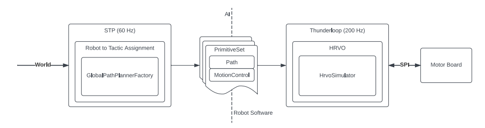
We are proposing a new motion planning architecture by taking advantage of the onboard processing power of Jetson Nanos by dividing the responsibility of robot navigation within a distributed system of the AI computer and the Jetson Nano, outlined in Figure 4.1. This architecture can be useful to other teams in SSL that wish to develop an obstacle-avoidance system that is scalable with a larger number of robots without incurring significant performance delays.
Through extensive research, we found that the Hybrid Reciprocal Velocity Obstacle (HRVO) algorithm effectively addresses the challenges faced by our previous architecture and improves upon our previous obstacle avoidance capabilities. By modelling the dynamics of nearby robots, the HRVO algorithm computes the set of all velocities that would lead to a collision. By only allowing velocities in the complement of this set, the algorithm is able to find collision-free velocities that ensure safe navigation for all robots. Furthermore, given that all friendly robots are running HRVO, the algorithm distributes the responsibility of collision avoidance evenly among all friendly robots, resulting in more efficient and coordinated movement. Given that this algorithm only considers the local area and filters out the robots which do not pose a risk of collision, it can run in Thunderloop—our main software loop—on the Jetson Nano at 200 Hz, as seen on the right hand side of Figure 4.1. To support the algorithm running faster than newly received Vision packets, we predict the movement of all other robots through a simple simulator running locally in Thunderloop. The main shortcoming of HRVO is that it is susceptible to not taking the shortest path when faced with large obstacles. To confront this, we run a path planner on our AI computer which calculates a general path that only considers large, static obstacles such as the defence area.
4.1.3 Static Obstacle Path Planning
Since the HRVO algorithm effectively considers moving obstacles such as robots, our path planner can be optimized to only consider static obstacles. Static obstacles are defined as stationary obstacles inside the field boundaries; these include both defence areas as well as the centre circle and enemy half during kickoffs. Our new path planner uses an external implementation of a grid-based Edge N-Level Sparse Visibility Graph (ENLSVG), which leverages the pre-processing of obstacles to calculate paths "an order of magnitude faster than existing algorithms such as Visibility Graphs, Anya and Theta*" [5]. By only storing a graph with "taut" edges, ENLSVG is significantly more scalable than Theta* by storing larger fields with comparatively less complexity. We leverage ENLSVG by creating path planners in a map that pre-processes every combination of static obstacles. Then, during gameplay, the AI quickly looks up the relevant pre-processed path planner with the given set of obstacles. We incorporated the fast planning capability of ENLSVG during robot-to-tactic assignment, seen on the left-hand side of Figure 4.1. Through qualitative testing, we noticed significantly fewer oscillations between tactic assignments during AI vs AI testing. An experimentally-determined resolution of 9 cm was chosen for a Division B field; this resolution allows the planner to compute 36 paths within 17 ms on a test computer, in-line with received Vision data.
Our proposed dual stationary obstacle and dynamic obstacle avoidance system can provide SSL teams with a flexible, scalable motion planning stack-up that can be integrated into a STP architecture for increased gameplay stability.
4.2 Hierarchical Finite State Machine (FSM) Play Architecture
We implemented a new play architecture that flexibly scales to more or fewer robots with transitions encoded in a finite state machine framework. Following the success of implementing tactics (per robot behaviours) with boost-sml [6] in 2022 [1], we have converted our play selection and transition architecture to a hierarchical FSM, as well. As with the tactic FSM system, we can have unlimited levels of hierarchy, i.e. every play can have its own "sub-play", and each "sub-play" can have "sub-sub-plays" and so on. Additionally, these plays can be reused in other plays, so the same FSM behaviour can be replicated in other contexts.
While in the STP framework [7], plays are a set of behaviours for the full team of robots, we modify this definition of Play to additionally accept as input the number of robots it must control, so that plays can be specialized for specific behaviours. That is, the play will generate tactics for a subset of the robots on the field depending on the number of robots being passed in. By controlling the behaviour of a subset of robots, multiple "sub-plays" can run concurrently and can specify coordinated behaviour of a small number of robots. For example, three robots can be given tactics from an offensive play to pass the ball around and look for shots, while the rest of the robots can be back home coordinating defense to block the most dangerous shot angles. Another advantage is adapting to fewer robots caused by non-functional robot or rule violations: If there are fewer robots, then each of the "sub-plays" can be given proportionally fewer robots or be eliminated entirely. As an example, if the opposing team has twice as many robots as us, we would likely run more defensive plays since scoring is much harder in that situation.
We found this play architecture useful for sharing multi-robot behaviours and especially for set plays. In set plays, most of the robots are doing ordinary defensive or offensive tasks, except for the one or two robots that need to kick the ball in a special sequence. Then, most of the robots can be controlled by normal plays and a few robots are given special tactics.
4.3 Thunderscope
In 2021, we identified a critical gap in our team's ability to reproduce and diagnose gameplay issues. This gap can be broken down into three main goals:
- Simulation should approximate the real world and be deterministic.
- Visualization should be fast, informative, configurable, and interactive. It should also be easy to add new visualizations.
- Testing should be made as easy and automatic as possible,
Our efforts have culminated in a visualization system called Thunderscope, which at a high level is a Python framework for connecting various pieces with unix socket communication. We use the Thunderscope Python script to launch separate processes that run simulation, visualization, and/or testing while managing the creation of unix socket communication from this parent process. Some of the data being communicated include commands for the robots, data about the world, and extra diagnostic information for visualization (e.g. the state of the play and tactic FSMs). The same Thunderscope script can connect to the unix sockets and forward the data to and from network sources, e.g. gamecontroller, robots, etc. The flexibility of the Thunderscope architecture means that we can easily launch multiple modes of the application, such as:
- An AI vs AI mode, where we pit two version of our AI controlling opposing teams and we can watch the outcome
- Interactive mode, where we can set up situations by manually moving the robots and ball around
- Asynchronous, headless testing mode, where a pre-determined situation is run as fast as the simulation and AI will allow, and the results are recorded for later analysis and replay (this is the mode that runs in our continuous integration on each pull request and merge in our repo)
- A replay mode, where Thunderscope only launches the visualizer and replays a recorded sequence
4.3.1 Simulation
For simulation, we adopted the Er-Force's framework simulator [8], and integrated it into a standalone simulator and a synchronous testing framework. We chose this simulator due to its accuracy in approximating the real world, the validation at Robocup 2021, as well as its interface in accepting velocity commands (which matches the interface within our firmware stack). We made our own copy of the simulator under the src/extlibs/er_force_sim directory of our software repo to give us full control over the simulation and we made several changes:
– Converted the simulator to run in synchronous mode, which means the simulator advances its simulation time based on time information passed into it, and does not advance simulation state independently.
- Updated interfaces so it integrates with our path planner and HRVO motion control system
- Improved interfaces to allow the ball and robots to be manipulated
- Various bug fixes including in determining robot angle
In the standalone mode of the simulator, we add a wrapper to the simulator to step the simulator according to real time.
4.3.2 Testing
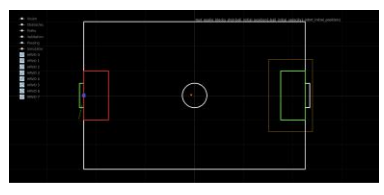
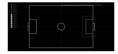
Testing is key to prevent regression in that we need to be sure that changes do not introduce bugs that cause a previously good AI to start breaking rules. As mentioned earlier, our efforts have mainly focused on developing tests that we can run in continuous integration, i.e. whenever there is a pull request or a merge into the repo. We have tried to make the process of debugging failures easier by showing the pass/fail condition for a test directly in the visualizer. For example, we expect the goalie to be in the crease defence area rather than being inside the net. Thus if the goalie in the test initially starts inside the goal, the crease defence is initially highlighted in red, and gets turned off as soon as the goalie enters the crease. This behaviour is seen in Figure 4.2.
4.3.2.1 Introspection and Replay
Through replay and introspection into the AI state, we can understand at the granularity of each AI step how the AI decided to enter the opposing defense area and when it made that decision.
4.3.2.2 Future Testing Directions
Future efforts in testing should involve playing and recording full refereed games in continuous integration, performing some automatic analysis, and presenting us with interesting clips that may reveal bugs or room for improvement. We have taken some steps in this direction, by having an asynchronous simulation and AI framework that can be run at faster than real time speeds, creating Thunderscope that can run two AIs against each other, and requesting an asynchronous interface for the autoref. We appreciate the efforts of Nicolai Ommer in fulfilling our request for that asynchronous interface. Unfortunately, higher priorities, such as improving the reliability of our robots has meant that this project remains stalled.
4.3.3 Visualization
We opted for a Python-based visualizer based on the PyQtGraph framework [9], which offers a low-code flexible way to implement visualizations of layers showing obstacles, speeds, and pass/fail conditions when running tests, in addition to the ordinary objects on the field like the robots, the ball, and field lines. PyQtGraph allows for additional panes to visualize plots and graphs to inspect specific values in the AI. We also implement replay record and playback controls directly with the PyQtGraph framework.
5 Conclusion
We believe that the design changes detailed above will lead to significant improvements in performance. We look forward to implementing these designs at RoboCup 2023.
6 Acknowledgements
We would like to thank our sponsors, as well as the University of British Columbia, specifically the Faculty of Applied Science and departments of Mechanical Engineering, Electrical and Computer Engineering, Integrated Engineering, Manufacturing Engineering, and Materials Engineering. Without their support, developing our robots and competing at RoboCup would not be possible.
References
- A. Almoallim, C. Sousa, D. Sturn, D. Antoniuk, F. Crema, H. Bryant, J. Lew, J. Liu, K. Wakaba, L. Bontkes, and Y. Zhou, "2022 team description paper: Ubc thunderbots," 2022.
- M. G. Nicolai Ommer, Andre Ryll, "Extended Team Description for RoboCup 2022," 2022.
- Z. Huang, L. Chen, Y. Li, J. Wang, Z. Chen, L. Wen, J. Gu, P. Hu, and R. Xiong, "Zjunlict extended team description paper for robocup 2019," 2019.
- P. Dumitru, G. Ellis, J. Fink, B. Hers, J. Lew, M. MacDougall, E. Morcom, S. H., C. Sousa, W. Van Dam, G. Whyte, L. Zhang, S. Zheng, and Y. Zhou, "2020 Team Description Paper: UBC Thunderbots," 2020.
- S. Oh and H. Leong, "Edge n-level sparse visibility graphs: Fast optimal any-angle pathfinding using hierarchical taut path," 2017.
- K. Jusiak, "boost-ext/sml," 2021.
- B. Browning, J. Bruce, and M. Veloso, "Stp: Skills, tactics, and plays for multi-robot control in adversarial environments," Proceedings of the Institution of Mechanical Engineers, Part I: Journal of Systems and Control Engineering, vol. 219, no. 1, p. 33–52, 2006.
- M. Eischer, P. Nordhus, and A. Wendler, "robotics-erlangen/framework," 2020.
- PyQtGraph, "PyQtGraph - Scientific graphics and GUI library for Python," 2021.