Compilation Error Team Description Paper for Small Size League of Robocup 2024
Yuxuan Wu, Kaiyang Liu, Jiaming Fan, Hao Zhang, Jiangyong Li, Minghe Wang, Qinfeng Li, Jun Li
Ningbo University of Technology, Zhejiang Province, P.R.China
Abstract Compilation errors have arisen from the robotics team participating in the Small-Size League (SSL) of robot soccer, affiliated with Ningbo University of Technology in Zhejiang Province, China. Our aspiration is to participate in the Robocup by 2024, and this article outlines the hardware specifications of our robot as well as the software advancements we have achieved. Our robot, meticulously crafted by our team, demonstrates a harmonious blend of mechanics and technology. Equally impressive is the software architecture of our robot, which integrates algorithms for path planning, ball prediction, decision-making, and more, resulting in an efficient and stable software framework. Our team has been diligently refining both the hardware and software components of our robot, aiming to make it competitive in the upcoming Robocup. Although there are numerous challenges ahead that we need to overcome and areas that require improvement, we are confident in our ability to create a robot that not only meets the competition standards but exceeds expectations.
INTRODUCTION
The Compilation Errors team, consisting of students from Ningbo University of Technology (NBUT), is gearing up to participate in the Robocup SSL. Formed in 2019, this multidisciplinary team boasts a membership of dozens of students majoring in Computer Science, Mechanical Engineering, and Electrical Engineering.
Since 2021, We have been busy preparing small-scale projects, with the ultimate aim of competing in the Robocup by 2024.
Despite the numerous challenges and issues their robot still faces, We are diligently working towards designing their first fully independent soccer robot, meeting the registration requirements set by the Robocup.
1 Hardware
In 2022, we meticulously crafted a batch of robots, acknowledging that they still have room for improvement. Consequently, we continuously seek skilled professionals in mechanical design, circuit design, and embedded development to join our team. It is heartening to note that several highly proficient technicians capable of replicating and further enhancing our designs have already come on board. Presently, we are steadily progressing towards the goal of refining our robot designs. Our aspiration is to showcase our robots' capabilities at the Small-Size League of the RoboCup in 2024.
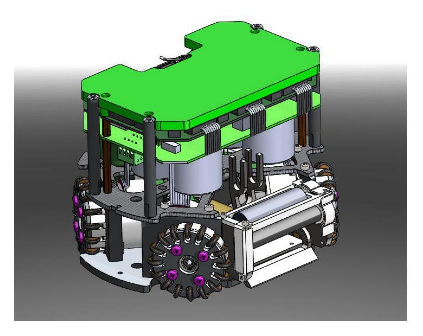
1.1 Single motion motor module
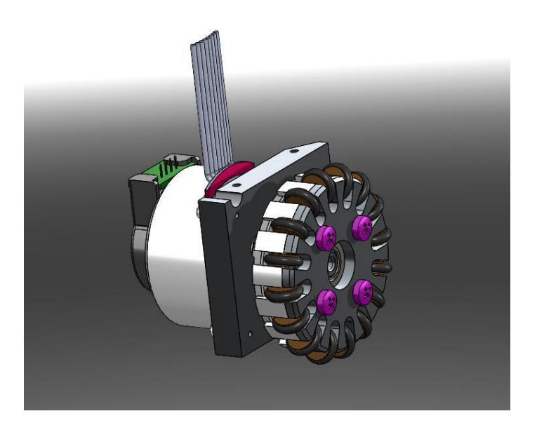
After multiple trials and careful consideration of both cost and performance, we have selected the 30W DC brushless motor - FL45BLW18-18V-3020B, custommade by Fuxing, for the individual motor module shown in the fig 2. This ensures efficient and stable power output. To precisely control the motor's rotation, we have chosen the HEDS brand's optical encoder - H9730 1000ppr. In terms of bearings, we have opted for the deep groove ball bearing 698ZZ, renowned for its excellent wear resistance and stability, ensuring smooth operation over extended periods. Furthermore, to fulfill the requirement of omnidirectional movement, we have designed the module with 16 small wheels, enhancing its flexibility and adaptability to various complex motion demands.
Robot Specifications
| Robot Specifications | |
|---|---|
| Max ball coverage | 16.4% |
| Dribbling motor | FL16SBL55-16V-200-12A |
| Driving gear material | 40Cr |
| Size | ø180×140mm |
| Weigh | 2.5kg |
| Driving motor | FL45BLW18-18V-3020B |
| Motor Encoder | H9730 1000ppr |
| Battery | Li-ion,14.8V 4s1p,2600mAh |
| Kicker charge | 4800uF 220v |
| height of center of gravity | 5.1cm |
| Wireless IC | nRF24L01+ |
| Compute module | STM32F407VET6 |
1.2 Electric Part
When it comes to the circuit design, We encountered numerous challenges during the circuit development process, and after numerous failed attempts, we are still facing various issues that need to be addressed. These challenges were highlighted during the 2023 Robocup China competition, where we continue to strive for circuit optimization and improved stability on the playing field.
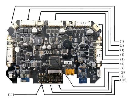
We have successfully integrated the circuits onto a main board and a boost board, ensuring both compactness and ease of maintenance. The main board features a high-performance STM32F407VET6 microcontroller, operating at a frequency of 168MHZ, and boasts an array of peripheral resources. This chip is utilized for signal processing, packet decoding, and motor control.
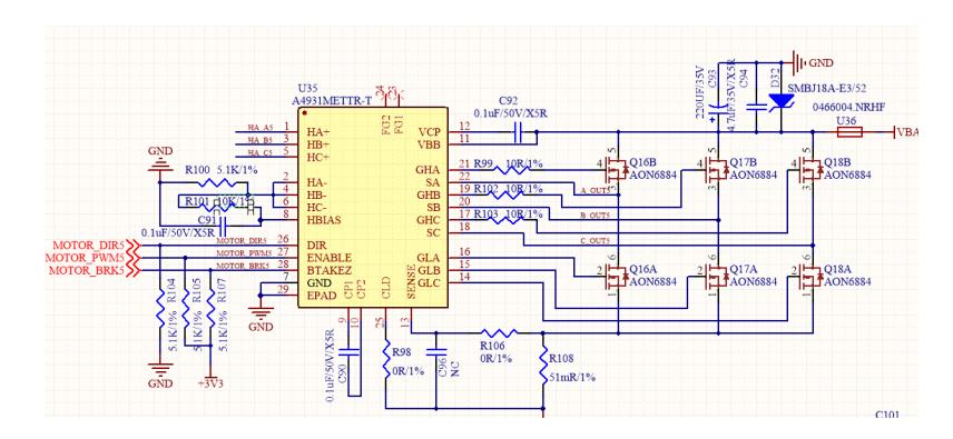
For the three-phase brushless motors, we have chosen Allergo's A4931METTR-T as the control chip, which not only simplifies the motor drive circuit design but also enables compatibility with both the movement and dribbling motors. During PCB fabrication, we employed thick circuit boards to ensure that even during collisions, the boards are resilient to any potential damage that could result in wire disconnections.
Motor Drive Part
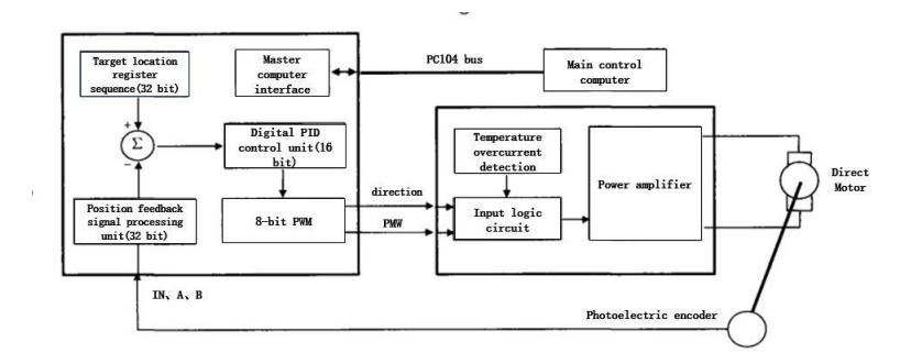
With regards to the motor drive, as shown in Figure 3, our first motor drive solution employed the A4931METTR-T as the pre-driver for the 3-Phase Brushless DC Motor, and the AON6884 as the MOSFET.
In terms of the encoder, we currently utilize a photoelectric encoder. However, during the competition, due to frequent collisions, the photoelectric encoder is prone to light interference, resulting in brief robot control loss. We have recognized this issue and are currently in the process of replacing the existing photoelectric encoder with a magnetic encoder to resolve this problem.
2 Robot test data
As a newly joined team, we conducted thorough parameter testing on our robot to provide everyone with a better understanding of its capabilities. Here are our test results:
In terms of velocity (VEL), our robot can achieve a maximum speed of 3283mm/s on the X-axis and 3357mm/s on the Y-axis. While these speeds are limited by the motor power, we believe there is still significant room for improvement.
Regarding communication (RECT), we have identified issues with high packet loss rates. To address this, we are optimizing our embedded code to reduce packet loss and resolve other related issues.
In terms of kicking (KICK), our flat-kick speed can reach 9.8m/s, far exceeding the competition limit. However, our chip-kick speed is only 1.4m/s. To address this, we are designing new coils and making adjustments to improve this aspect. We have modified the kick coil from 460 turns to 200 turns to improve its performance.
For dribbling (DRIBBLE), our robot maintains a stable ball-holding state in most situations, with a dribbling speed of 3.1rad/s. However, when pulling the ball backward, it is prone to dropping the ball. We will focus on optimizing this aspect further.
We hope these test data provide more information about our robot's performance. We will continue to strive for optimization and improvement to achieve better results in the competition.
Robot performance
| Robot performance | ||
|---|---|---|
| vel | vx(mm/s) | 3283 |
| max-acc-x(mm/s²) | 2090 | |
| vy(mm/s) | 3357 | |
| max-acc-y(mm/s²) | 1893 | |
| rect | error ratio | 0.109 |
| error-right(mm) | 87.45 | |
| error-down(mm) | 132.44 | |
| error-left(mm) | 34.10 | |
| error-up(mm) | 145.04 | |
| kick | flat-kick-max(m/s) | 9.8 |
| flat-STD(mean in 20 tries(6m/s)) | 6.8% | |
| chip-kick-max(m/s) | 1.4 | |
| chip-STD(mean in 20 tries(4m)) | 15.2% | |
| dribble | dribble vx(m/s) | 0.48(a=3.0m/s²) |
| dribble vy(m/s) | 1.25(a=3.0m/s²) | |
| dribble vw (rad/s) | 3.1 |
3 Software
(No introductory text for this section)
3.1 Shake off defenders with a ball-handling crossover
First, we establish the ball-controlling vehicle as the reference point and construct a designated area around this central point. Within this area, we carefully position six evasion points. These points are distributed following a 60-degree angular increment and a 100mm distance increment, ensuring their uniform and orderly distribution around the central point. However, there's a crucial condition: any point whose connection line with the ball-holding or ball-receiving vehicle is obstructed by an enemy vehicle will be excluded.
After these preset evasion points are established, we employ the TOPSIS algorithm to meticulously evaluate them. This assessment aims to ensure that each evasion point meets specific criteria and requirements, as follows:
- For each evasion point, we have established the following evaluation metrics:
- The nearest vertical distance between enemy vehicles and the line connecting the evasion point to the ball-receiving position. This metric assesses the direct threat level posed by enemy vehicles to the evasion point.
- The angle formed between the ball-receiving position, evasion point, and the nearest enemy vehicle. This metric gauges the positional advantage of the evasion point within the tactical layout.
- The distance between the evasion point and the nearest enemy vehicle. This metric directly reflects the safety of the evasion point.
- The sum of distances between all enemy vehicles within a 500mm radius of the evasion point and the evasion point itself. This metric assesses the density of enemy vehicles surrounding the evasion point.
- The distance between the evasion point and the central point. This metric ensures that the evasion point is neither too close to the ball-controlling vehicle nor too far away, maintaining tactical flexibility and efficiency.
These evaluation metrics comprehensively consider the safety, positional advantage, and tactical efficiency of each evasion point, providing a comprehensive and accurate basis for subsequent TOPSIS algorithm assessments.
After calculations, we obtained a scoring matrix Z, which encapsulates the performance scores of each evasion point (vector n) across various evaluation criteria (vector m). This matrix provides us with detailed data regarding the performance of the evasion points, laying a solid foundation for subsequent TOPSIS algorithm assessments.
Standardization Processing: Do the following for one of the elements in Z
$$Z_{ij} = x_{ij} / \sqrt{\sum_{i=1}^n x_{ij}^2}$$
- Calculate the score and normalize:
$$Z = \begin{bmatrix} z_{11} & z_{12} & \dots & z_{1m} \ z_{21} & z_{22} & \dots & z_{2m} \ \dots & \dots & \dots & \dots \ z_{n1} & z_{n2} & \dots & z_{nm} \end{bmatrix}$$
Define maximum $$Z^+ = (Z_1^+, Z_2^+, ..., Z_M^+) = (MAX(z_{11}, z_{21}, ..., z_{n1}), MAX(z_{12}, z_{22}, ..., z_{n2}), ..., MAX(z_{1m}, z_{2m}, ..., z_{nm}))$$
Define minimum $$Z^- = (Z_1^-, Z_2^-, ..., Z_M^-) = (MIN(z_{11}, z_{21}, ..., z_{n1}), MIN(z_{12}, z_{22}, ..., z_{n2}), ..., MIN(z_{1m}, z_{2m}, ..., z_{nm}))$$
Then Defines the distance between the i-th (i=1,2,...,n) evaluation object and the maximum value $$D_i^+ = \sqrt{\sum_{j=1}^m (Z_j^+ - z_{ij})^2}$$
Defines the distance between the i-th (i=1,2,...,n) evaluation object and the minimum value $$D_i^- = \sqrt{\sum_{j=1}^m (Z_j^- - z_{ij})^2}$$
So We can calculate the unnormalized score of the i-th (i=1,2,...,n) evaluation
$$S_i = (D_i^-)/(D_i^+ + D_i^-)$$
Clearly: $0 \le S_i \le 1$, The larger $S_i$ is, the smaller $D_i^+$ is, and the closer it is to the maximum value.
We can normalize the score: $\tilde{S}i = S_i / \sum{i=1}^n S_i$, so $\sum_{i=1}^n \tilde{S}_i = 1$
- After undergoing standardization, the scoring matrix Z has provided us with normalized scores for each evasion point across various evaluation criteria. To identify the most performant evasion point, we proceed to sort the final scoring vector S.
The sorting process involves arranging the comprehensive scores of each evasion point in descending order. Consequently, the evasion point with the highest score is placed at the top. Through this step, we can unambiguously determine the outstanding performer among all evasion points — the optimal evasion point. The meticulously designed and calculated optimal evasion point serves as a crucial basis for further analysis and decision-making. This information provides valuable support in various contexts, such as resource allocation, strategy adjustment, and other practical applications. With its assistance, we can make informed and efficient decisions.
3.2 Determine the best ball handling machine
For the main offensive player's matching problem, we adopt a unique algorithm to bypass the traditional "match" matching method. The traditional matching method mainly judges based on the distance between the player's current position and the target position. This method is too simple and does not fully consider factors such as the speed of the ball and the position of enemy players, so it is more suitable for our defensive players' task matching. However, for the complex positional relationships of offensive players and the changing state of the ball, we need a more refined matching algorithm.
In the matching of offensive players, we focus on finding the best controlling players and receiving players. For the controlling player, if the ball is stationary, we will match based on the ball's coordinates; when the ball speed increases, we will use each player's interception time as the criterion for judgment. The judgment of interception time is closely related to each player's reception point. Before starting the match, we will calculate each player's optimal interception point through a specific algorithm.
The basic idea of this algorithm is: during the ball's movement, based on the measured friction and current speed, estimate where the ball will roughly stop. We calculate the time it takes for the ball to travel this distance and divide it by 100 to divide the time into smaller increments. Then, we convert this time into corresponding reception points, add the initial coordinates of the ball plus each distance vector, and calculate the time it takes for each of our players and enemy players to reach these points. We set a time threshold to determine if the player can successfully intercept the ball and return the coordinates of the player's optimal interception point.
After calculating each car's optimal interception point and shortest interception time, we store this data in variables for subsequent algorithm comparison. From this data, we select the optimal interception car. It is worth noting that the defenders around our own penalty area will not participate in the selection of controlling cars and interception cars to ensure the solidity of defense and prevent giving up possession in front of our own penalty area.
After selecting the optimal controlling car, we will record its serial number. The selection of interception cars is done by calculating and returning car numbers in CUDA.
3.3 Judge the state of the ball
When determining the status of the ball on the field, we calculate the interception times of the best interception cars for both teams to determine which team is in possession of the ball. We will then detail the process of calculating the interception time. If the enemy team is in possession, the corresponding status is "GetBall". In the "GetBall" state, our playing style becomes more conservative. When the pressure in our own half is high, we will abandon one attacking car to focus on defense. Conversely, if our team is in possession, the status changes to "Pass", and we will add one more attacking car making runs. To avoid frequent state transitions, I have set a 0.5-second interval. The state can only begin to switch after a forced 0.5-second delay, which increases the stability of our state machine system and prevents excessive changes in cars tasked with different tactics. Excessive changes can lead to instability at the tactical level. This design also helps us modularize our state machine, making it easier to modify in subsequent iterations. We only need to modify the corresponding tactics or actions going forward.
3.4 Man-marking defensive tactics optimization
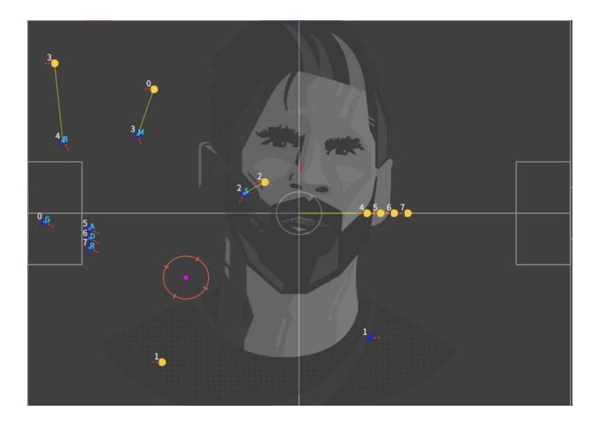
In multi-robot collaborations, defense plays a crucial role. When the enemy initiates an attack, our robots must effectively halt their offensive momentum. Traditional man-marking defense strategies primarily involve two approaches: standing on the direct line between the defender and the ball, or positioning oneself between the defender and our own goal. However, this obvious defensive intention can be easily detected by the enemy robots, potentially causing them to avoid passing the ball to the marked robot.
To improve upon this strategy, I propose a novel defensive approach: selecting a position that the enemy believes is unprotected by us, but in reality, it is securely guarded. This way, the enemy might choose to pass the ball to the marked robot, allowing our robot to intercept it a step ahead. This defensive position is determined through precise calculations.
Specifically, we first calculate the intercept point of the enemy robot. Then, we grid the distance between this intercept point and our own goal into 10 segments. Additionally, we grid the angle between the ball, the enemy's receiving point, and our own goal into 10 segments as well. Next, we calculate specific defensive points based on these distances and angles, and assign scores to them. Finally, we select a point that offers both an appropriate distance and angle, while also bypassing the enemy robot's defensive judgment, as the man-marking defense position.
This defensive strategy not only enhances defensive efficiency but also increases the difficulty for the enemy robots to make passes. By directly applying this defensive point in our skills and using it as a matching condition for subsequent robot pairings, we can further elevate the defensive capabilities of multi-robot collaborations.
3.5 Guard defense point algorithm
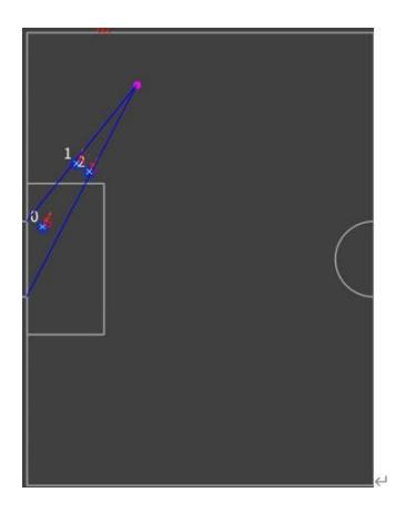
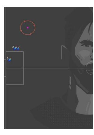
The role of the defender is indispensable in any game, whether it's during offensive plays in the front or defensive strategies in the back. Their close marking and unwavering focus are crucial to preventing any goal conceded. Hence, the stability of the defender is paramount. To ensure this tactical stability, we have separated the positional calculation logic into a dedicated cpp file. This allows the computed positions to be seamlessly integrated into the lua scripting, facilitating character matching and positioning.
Unlike the traditional elliptical defense approach, we have adopted a rectangular defense zone aligned with the new rules. This design choice brings the defenders closer to the penalty area, optimizing their defensive efficiency. The elliptical method might leave gaps in corner positions, providing enemy attackers with opportunities to exploit.
Furthermore, our algorithm accommodates varying numbers of defenders. The defensive strategy expands outward from the center, gradually encompassing the sides. At the intersection of the line connecting the ball to the midpoint of our goal and the outer rectangle, we continue to diffuse the defense line towards the sides. The spacing between two robots is limited to less than the diameter of a ball, maximizing the positional advantage of the defenders.
When the absolute value of the angle between the intersection point and the goal post exceeds the absolute value of the angle between the boundary coordinate along the x-axis in front of the penalty area and the goal post, the intersection point remains stationary. This approach aims to maximize the effectiveness of both the goalkeeper and the defenders, ensuring rapid defensive reactions when the enemy executes a low cross.
By implementing these strategies, we aim to enhance the defensive efficiency and stability of our team, laying a solid foundation for our victory.
3.6 Automatic parameter adjustment system
In the competition, parameter tuning is a crucial step. Since the parameters of each robot are unique, parameter tuning becomes particularly important. These parameters include friction, touch compensation angle, and the relationship between actual and kicking force. To ensure the optimal performance of the algorithm, we need to tailor the parameters for each individual robot. This underscores the critical role of parameter tuning in the competition.
However, for many teams, parameter tuning is a time-consuming process. It requires significant manual effort and often requires trial and error adjustments. To simplify this process and reduce costs, we have developed an automatic parameter tuning script. This script can automatically collect and fit data, greatly reducing the time and effort required for parameter adaptation.
Currently, we are developing parameter tuning algorithms based on different parameters. Our goal is to create a flexible and scalable solution that can adapt to various robots and competition conditions. Through continuous optimization and adjustments, we hope to use these algorithms to tune parameters for the 2024 Robocup, ultimately improving our team's performance.
Conclusion
Our team has made significant advancements in developing a robot for the 2024 RoboCup Small-Size League. Despite encountering numerous issues and challenges, we remain steadfast in our belief that we can create a highly competitive robot that not only meets the competition standards but also exceeds expectations. As we persist in refining both the hardware and software components of our robot, we eagerly await the opportunity to participate in the upcoming RoboCup and achieve further accomplishments.
References
- Zheyuan Huang, et al.:ZJUNlict:RoboCup SSL 2018 Champion Team Paper. RoboCup 2018 small size league champion. Robot Soccer World Cup. Springer, Berlin, Heidelberg, 2018.
- Nicolai Ommer, Andre Ryll, Mark Geiger.:TIGERs Mannheim Extended Team Description for RoboCup 2019. RoboCup Wiki as extended team description of TIGERs Mannheim team, Leipzig, Germany, accessed April 5(2019): 2019.
- Yonghai Wu, Yue Zhao, Rong Xiong, ZJUNlict Team Description Paper for RoboCup2013
- Yue Zhao, Rong Xiong, Hangjun Tong, Chuan Li and Li Fang ZJUNlict Team Description Paper for RoboCup 2014
- Takumu Hirohashi, Ryusei Hotta, Takayuki Tasaka, Yudai Matsumoto, Koshi Wakabayashi, Daiki Tomioka, Yuzuru Naito, Kaito Mitsuishi Takae Obara, Ai Mitsushima, Ryosuke Murai, Sazuka Okunishi Koutaro Ochiishi, Shutaro Otake RoboCup 2023 TEAM DESCRIPTION PAPER Ri-one
- Jiawei Lin, Jie Chen, Baiji Chen, Kaichong Lei, Zikang Shi, Jiaping He,Zhengwei Qin, Jiaxuan Xie, Jingwei Xu, Zhaocong Liu, Ruiqing Ge, and Li Hao SRC Team Description Paper for RoboCup 2020
- STmicroelectronics.STM32F407xx Datasheet, https://atta.szlcsc.com/upload/public/pdf/source/20140322/1457707027869.pdf
- Allegro.A4931 3-Phase Brushless DC Motor Pre-Driver Datasheet, https://atta.szlcsc.com/upload/public/pdf/source/20180122/C89724_15166131725631291885.pdf
- Chuan Li, Wenjian Tang, Lisen Jin Yangsheng Ye, Xiaoxing chen, Lingyun chen and Rong Xiong ZJUNlict Extended TDP for RoboCup 2015
- Joydeep Biswas, Philip Cooksey, Steven Klee, Juan Pablo Mendoza, Richard Wang, Danny Zhu, and Manuela Veloso CMDragons 2015 Extended Team Description
- Joydeep Biswas, Philip Cooksey, Steven Klee, Juan Pablo Mendoza, Richard Wang, Danny Zhu, and Manuela Veloso CMDragons 2015 Extended Team Description
- Andre Ryll, Mark Geiger, Nicolai Ommer, Arne Sachtler, Lukas Magel.: TIGERs Mannheim Extended Team Description for RoboCup 2016. RoboCup Wiki as extended team description of TIGERs Mannheim team, Leipzig, Germany, accessed April 18 (2016): 2019.