Delft Mercurians Team Description Paper RoboCup 2024
Delft Mercurians Team
Delft University of Technology
Abstract This paper goes over the progress the Delft Mercurians team has made in the past year in terms of robot design and development, to compete in RoboCup Small Sized League division B. The paper presents the hardware, embedded-electrical, and software aspects of the robot as well as the research done into smart strategy-making. The future plan for the team is also described.
Introduction
Delft Mercurians is a multidisciplinary RoboCup Small Size League team based in Delft, the Netherlands, that aims to debut in Robocup 2024 [1]. The team was founded in September 2022 by members from the Robotics Students Association (RSA) and is comprised of robotics enthusiasts and students of the Technical University of Delft. Currently, the team consists of twenty-three members divided into four departments: Hardware, Embectrical[1], Software and Magic[2]. This paper will outline the integral components that each department has worked on, with an emphasis on describing their innovations.
[1] Embectrical is a concatenation of the words embedded and electrical. This term was adopted from the Project MARCH Dream Team based in Delft.
[2] The magic department focuses on applying machine-learning to perform smart and adaptive control.
System Overview
A comprehensive system overview of the robot is presented below.
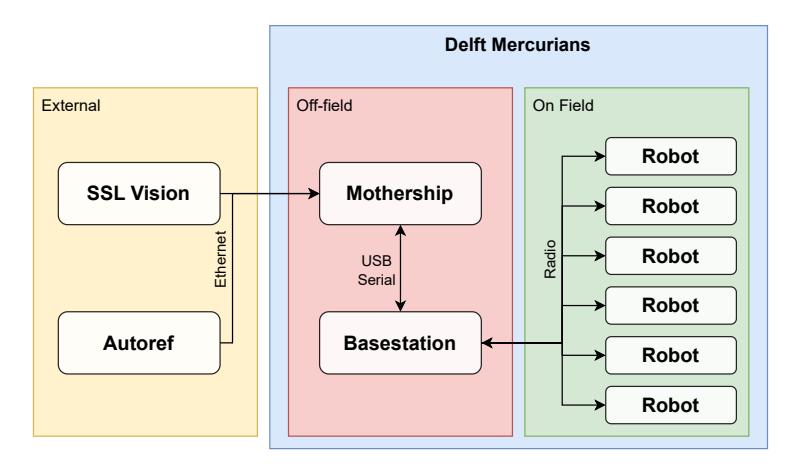
Hardware Overview
The following table summarizes the key specifications of the current robot design.
Robot Hardware Specifications for v2024
| Robot Version | v2024 |
|---|---|
| Dimension | 176 × 149mm |
| Total Weight | 1970g |
| Wheel Motors | Nanotec DF45L024048-E 65W |
| Wheel Gearing | Direct Drive |
| Dribbling Motor | ECU22048H24-S113&M16-1024 55W |
| Dribbling Gearing | 1:1 (18 teeth Mod 1. POM gears) |
| Dribbling Bar | 10mm (PT flex 60) |
| Main microcontroller | STM32F103C8T6 |
| Radio | nRF24L01 |
| Motor Drivers | B-G431B-ESC1 |
Hardware
This section is about the hardware design and innovations the team has made, the challenges that were encountered as well as the solutions to those challenges.
Active Aerodynamics
In the MicroMouse competition, it was demonstrated that the addition of a fan to decrease static pressure under the robot would increase performance as the increased traction allows for higher accelerations. Ever since its introduction, the downforce fan has become a staple in Micromouse competitions and has become a necessity for teams to remain competitive [2]. Inspired by this innovation, research was conducted to test its applicability in the Robocup SSL division. To test this concept a small impeller was used to suck air through the baseplate, illustrated in Figure 2a. The negative pressure created over the surface area of the base plate creates downforce, which increases traction as well as the maximum achievable acceleration.
Similar design characteristics can be seen in the RoboCup SSL competition, where a large round baseplate is used on robots that move over a largely flat surface. With regards to suction, the key difference between Micromouse and Robocup SSL robots is the weight of the robots; a MicroMouse robot weighs only 115 g and can generate over 500 g of downforce [3] whilst requiring low power. The reason MicroMouse robots can generate such high forces is due to the smoothness of the surface over which they operate. Its proximity to the ground increases the negative pressure due to the drag over the baseplate surface. Conversely, RoboCup SSL robots have a weight range of 2.0 kg to 2.5 kg and are subject to changing field conditions with varying roughness.
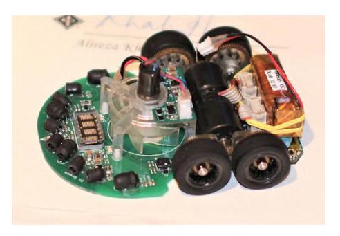

Consequently, the efficacy of the suction concept is greatly dependent on the field conditions, which in turn determines its usefulness in the competition. The primary value in the suction concept lies in reducing the slip of the wheels under maximum load, an issue many teams have deemed to be the root cause of faulty velocity estimation [5] or the main limiting factor in acceleration [6]. One way to increase traction is to increase the weight of the robot, usually done by increasing the weight of the baseplate which also lowers the center of mass. However, having more mass to accelerate results in higher power demand with little to no gain in acceleration. The suction concept on the other hand has the potential to increase the traction force more than the additional weight from the added systems to generate the downforce, leading to higher maximum acceleration.
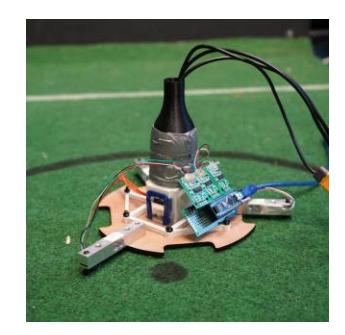
To test the full capabilities of the concept, a test setup was made as seen in figure 2b, where three load cells measured the total force due to the suction generated by a central source. In the best case, a 800W vacuum cleaner generated a peak downforce of 34.8 N as seen in figure 2b with an ideal duct on a relatively rough field. This validated the concept and allowed the team to develop a solution that would fit within the power and size requirements of the robot.
With the knowledge gained through the testing setup and the MicroMouse competition, attempts were made to try and design a solution in-house. However, it was understood that the fidelity and balance requirements for high rotational speeds would make manufacturing costly and time-consuming. Hence, exploration was done into existing solutions that could be integrated into the robot. A reasonably priced solution with decent performance was found and was further tested. Using the new fan, an average downforce of 11.4 N was measured while using 153W of power, which was considered sufficient for the concept and was further refined for the competition.
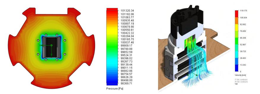
Additional CAD-aided simulations were done in SolidWorks Flow Simulation to validate the basic working principle and limiting design elements of the ducting. These simulations were not used to determine the efficacy or efficiency of the design but to investigate peculiar behavior or characteristics in the design. The latest results can be seen in figure 3.
A downside of the solution is the noise generated by the fan under load which necessitated research into sound dampening and isolation. Using a converging nozzle above the fan already resulted in a noise reduction from 98.2 dB at 2.51 KHz to 84.9 dB at 2.47 kHz. Further noise reduction is expected from improvements to damping and further isolation as the robots are still being developed.
Batteries
Throughout the history of RoboCup, limitations in current output and dynamical load performance have led to most teams opting for a Lithium Polymer (LiPo) solution to power the robots. However, in recent years, advancements in Lithium Ion (Li-Ion) batteries have allowed for much greater current output with reasonable drops in voltage.
When initially designing the robot, two 3S LiPo batteries of 2.20 Ah capacity were used to provide power. Battery sizing was made to be similar to that of other teams. However, the inclusion of the impeller fan led to an increase in energy requirements. The inflexible nature of LiPo battery packaging meant that the battery had to be placed higher up, elevating the center of gravity and reducing stability.
This led to the investigation for a better power source, during which the team found a set of high current 18650 Li-Ion batteries (Epoch 18650 2.8 Ah 40.0 A). A six-cell battery pack provides 60.0Wh of energy and is 20% lighter (330 g to 270 g) than the aforementioned LiPo solution. Furthermore, the cells were split into two triangular packs which neatly fit in the bottom of the robot, lowering the center of gravity, as seen in figure 6. The battery pack is the purple component.
0.15 mm copper-nickel sandwich strips were used to connect the cells and a 3D printed mount was used to hold the batteries together. A Battery Management System (BMS) was attached to each pack for safety, which also balances the cells. This can also be seen in figure 6. It should be noted that a high-power spot welder is needed [7] for this process as budget welders lack the energy output to weld copper.
The implementation of a smart BMS (JK-JBD4A8S4P) was also considered as it would allow for real-time state-of-charge monitoring, active equalization, and over-temperature protections. However, the BMS together with the large heat sinks weighs over 160 g and is 110 x 73 x 17.0 mm in size. Due to space limitations and the added hardware and embectrical complexity, the team decided to temporarily forgo this addition and stick to the basic one. This idea will likely be explored in future iterations of the robot.
One of the downsides of using a Li-Ion solution is the voltage drop during high load / dynamical load. The continuous power consumption and the discharge characteristic are shown in figure 4 [8].
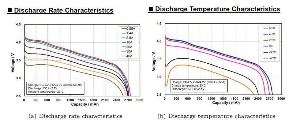
Each battery pack consists of three batteries connected in series, and the robot could draw up to about 32.0 A so the expected voltage drop is about 2V at peak consumption. Hence, each robot would need two of these battery packs, making the overall battery configuration 6s.
For dynamical loading, a stress test was conducted using 2 test packs with Samsung INR18650-35E 3.40 mAh - 8.0 A cells. The impeller fan and the movement motors were activated in two steps and results are shown in the graphs in figure 5.
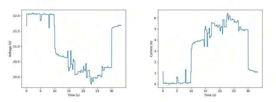
Taking into account the discharge rate characteristics provided by LYGTE [9], the voltage drop falls within the range of our prior assumptions. Extrapolating the team's results onto the 40.0A cells it was concluded that similar results would be obtained on the final robot. However, despite being rated for 8A nominally, it was believed that the setup at that time was not fully representative of the actual robot did not have the capability to draw more than 6A.
Wheels
Early on in development, it became clear that the majority of commercially available wheels were not ideal for the application due to their small diameters and large play in the sub-wheels. Furthermore, the decision to switch to direct drive called for larger diameter wheels. Thus, custom wheels had to be designed. The goal was to allow the robots to drive smoothly while having a modular design for easy manufacturing. The final design consisted of a PLA print sandwiched between two steel plates. The PLA component contains a wire that is inserted in all the sub-wheels to hold them in place.
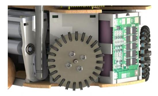
X-rings were chosen for the sub-wheels instead of o-rings as these make the robot drive more smoothly than the regular o-rings and also provide higher traction [10]. PLA sub-wheels are printed to keep the x-ring on the sub-wheels and to protect them from the steel plates. These wheels can be swapped out quickly, allowing the ride height of the robot to be adjusted to optimize the suction fan's downforce generation. However, the PLA components are prone to deformation under prolonged use, as demonstrated by other teams that solved the problem by switching to POM and ABS [10]. Due to budget and manufacturing limitations, the current wheels are still printed in PLA, but this is subject to change in the future as the team grows and becomes more established.
Embedded & Electrical
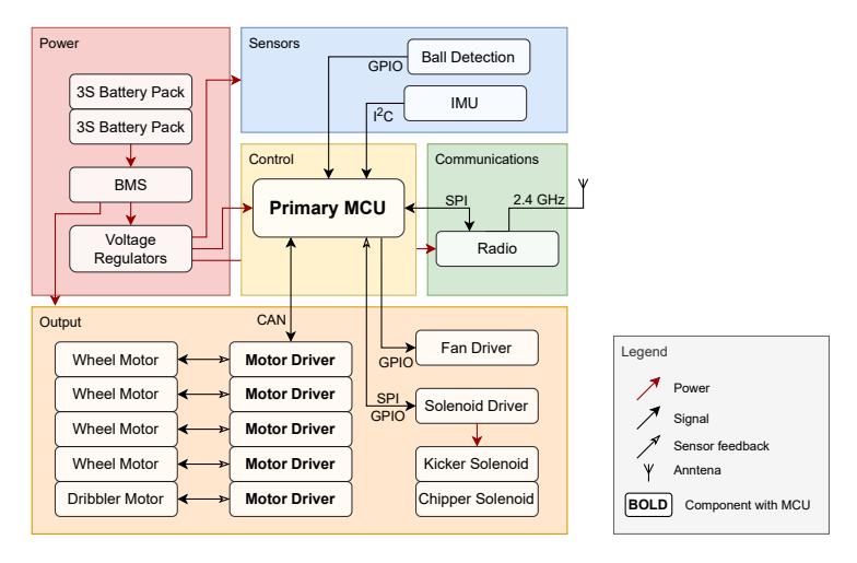
An overview of the robots' internal subsystem structure is shown in Figure 7. This chapter aims to highlight some of the key innovations and differentiating factors while leaving out trivial details.
Rather than using one monolithic microcontroller to control everything at a low level, the subsystems are decoupled wherever possible. This creates a modular design and improves overall reliability. Each motor driver is powered by its own microcontroller, and in the future the kicker subsystem will be as well. If any individual subsystem fails, most of the robot can remain functional. This also reduces the need for complicated embedded programming, as each microcontroller can "focus" on a single task.
Motor Drivers
The motor drivers hold the key to good performance of the robots. The better the underlying motion control of the wheel motors, the better the mobility of the robot, and the better it can perform during a match. However, due to limited available knowledge of motor driver circuit design and lack of access to assembly facilities, commercial motor drivers were used. The B-G431B-ESC1 development board by STMicroelectronics was identified as being a cost-effective and compact option for motor control.
In order to reliably connect to and communicate with the off-the-shelf motor driver boards, a carrier board was designed. The PCB provides mounting points and easy electrical interfacing connections (see Figure 8). This solution is similar to that of RoboFEI [11], but more of the built-in interfaces are exposed, namely the CAN, UART, and motor-to-encoder connection interfaces. Power is delivered directly through the mounting holes, which eliminates the need for bulky connectors on the board and saves space.
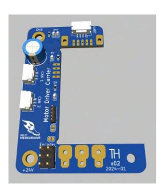

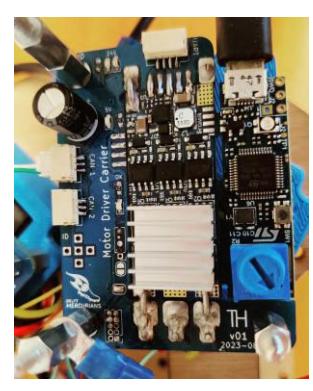
A partnership was established with STMicroelectronics. In exchange for motor drivers, the team will provide feedback for the products to improve the accessibility of brushless motor control. During experimentation, a few issues with the board were identified, which could potentially be addressed in future iterations. These difficulties included the connection between the board and the outside world, as well the built-in CAN termination switch which sometimes malfunctioned.
For the control software, the open-source SimpleFOC [12] library was used. While this has caused numerous issues, the team hopes to be able to contribute to the development of the library, again with the goal of improving the accessibility of high-performance brushless motor control.
Controller Area Network (CAN) Bus
For the robots' internal components communication, the CAN protocol was chosen as the communication protocol over the more common alternatives as as Serial Peripheral Interface (SPI) and Inter-Integrated Circuit (I2C). The CAN bus is more extendable, reliable, and flexible in the current system, where several microcontrollers frequently communicate with each other while handling sensor readings. Note that SPI and I2C still have to be used for some interfaces.
CAN communication is based on a message architecture, which, combined with its built-in priority system, enables efficient handling of data packets, while allowing the flexibility of designing tailor-made protocols to improve throughput and efficiency. For example, speed commands to the motors can be sent in a single frame, instead of having to send individual frames to each controller.
The CAN bus has many built-in error-correction and -detection features, from the use of 2-wire differential signaling and CRC checks, to message acknowledgment and automatic re-transmission. Another compelling advantage of CAN is its multi-point network-like connectivity, which simplifies interfacing and wiring units compared to typical point-to-point connections.
It is worth noting that several challenges were encountered when setting up the CAN bus, particularly in software development and maintenance. The messagebased nature of CAN imposes a higher programming overhead compared to other methods, as the proper message exchange is facilitated by predetermined message identifiers, unit IDs, and data types. Any extension or modification of the communication or exchanged information types between units has to be specified in the software program and must be shared (i.e., as a shared library) when programming all units' microcontrollers.
Software
(Section introduction text would appear here if present in original)
Software Architecture
The behavior of all players on the field is coordinated by a central control server, termed the Mothership, which is also responsible for communicating with the league software and displaying information to the developers on the team.
Initially, an investigation was done into using frameworks built by other more established teams, such as ER-Force's Ra framework [13]. However, building software from the ground up in-house was determined to be more beneficial, as it brings maximum flexibility and performance.
The Mothership software is divided into two main components: AI and framework. The AI component is responsible for the high-level planning; the underlying framework handles communicating with league software, low-level trajectory control for the robots, game state tracking, and safety features.
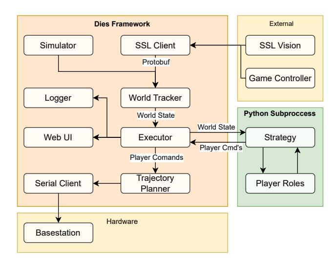
The framework also has tools to enable easy iteration on the strategies, mainly two components: Runtime and Environment. Runtime is a separate process responsible for initializing and communicating with the AI. Its decoupled nature allows the AI, which is written in Python to take advantage of widely available tooling, and prevents crashes in the AI from affecting other processes. Environment is responsible for connecting to the game controller, the simulator, and the robots, as well as for the communication to and from these components. This abstraction allows the framework to support different environments. The framework is written fully in Rust, as it has performance guarantees, is memory-safe, and prevents unexpected behaviors.
The framework is open-sourced and publicly available under the name Dies[3]. The source code is published on GitHub at https://github.com/DelftMercurians/Dies.
[3] Pronounced dai-ez, named after the Roman god of day and mother of Mercury, which follows the theme of the name of the team
Model Predictive Control (MPC)
In order for the robot to avoid collisions in a dynamic environment, MPC was implemented for local obstacle avoidance. Firstly, a discretized state space model of the robot dynamics was made. As the first approximation, the robot dynamics model is holonomic, so it is defined as
$$\vec{x}[k+1] = \begin{bmatrix} 1 & 0 \ 0 & 1 \end{bmatrix} \vec{x}[k] + T_s \cdot \begin{bmatrix} 1 & 0 \ 0 & 1 \end{bmatrix} \vec{u}[k], \tag{1}$$
where state $\vec{x}$ is the position in the x and y directions, $\vec{x} = [x, y]^{\top}$, $\vec{u}$ are the velocity inputs sent to the robot, $\vec{u} = [v^x, v^y]^{\top}$ and $T_s$ is the sampling time. With the given state space, the cost function and the constraints could be defined as
$$J = \sum_{k=0}^{N-1} \left[ |x_k - r_k|_Q^2 + |u_k|_R^2 \right] + |x_N - r_N|_Q^2.$$
Where $r_k$ and $r_N$ are the desired positions and R and Q are weighting matrices, which determines whether the tracking error or the control input has priority in the cost function. The cost function is then defined as the error between the current state and the target with the lowest input values possible. Following this, the optimization problem can be defined as
$$\min_{u_k} \sum_{k=0}^{N-1} \left[ |x_k - r_k|_Q^2 + |u_k|_R^2 \right] + |x_N - r_N|_Q^2.$$ (2)
Thereby formulating a function that moves the robot to the target location. Obstacle avoidance is done by subjecting the cost function to additional constraints that prevent contact between the robot and obstacles. They are defined as
$$||p_r - p_o||_2 \ge r_r + r_o,$$ (3)
with $p_r$ and $p_o$ being the centers of the robot and obstacle, respectively, and $r_r$ and $r_o$ being the radius of the robot and obstacle, respectively. Hence, the constraint does not allow the distance between the centers of the robot and the obstacles to be smaller than the sum of their radii, thereby keeping them from coming into contact. The optimization problem was also subjected to velocity constraints, so the calculated trajectory is physically achievable. Since the statespace model does not involve acceleration it is not constrained.
The full optimization problem is then formulated as
$$\min_{u_k} \sum_{k=0}^{N-1} \left[ |x_k - r_k|_Q^2 + |u_k|_R^2 \right] + |x_N - r_N|_Q^2$$
subject to $|p_r - p_o|_2 \ge r_r + r_o$ .
subject to $\vec{v} \le \vec{v}_{lim}$ (4)
With the cost function and the constraints defined, the casADi solver is then used to solve the optimization problem in a given environment, either dynamic or static. This formulation was inspired by RoboDragons' 2022 ETDP [14].
Magic
(Section introduction would appear here if present in original)
Motivation
While Software team strategy analysis happens with the help of MPC, several issues arise when attempting to apply it in the real world. The issues can be separated into two main families: Limited horizon length and adaptability.
Limited horizon length is an issue because the system needs to make longterm plans. However, with the current implementation, MPC is modifying highfrequency actions, which in turn limits the horizon length. Even though the pipeline is implemented in Rust, the complexity of the prediction grows exponentially with the horizon length, thus leading to bounds on the effective horizon, while the system should be able to make predictions with an unbounded time horizon.
Adaptability is a common issue of many MPC approaches. It lies in the fact that they are not able to adapt to the model of the world; MPCs usually assume a single, rigid, model of the world, that is specified via an implementation of the simulator. The simulator used for the MPC pipeline is Rapier, which is likely not capable of representing all possible field parameters well. Hence, the robot would be unable to adapt to the unknown parameters of the real world, either in real-time throughout the game, or on a per-field basis.
Method
One of the possible solutions to the aforementioned problems is the use of Reinforcement Learning (RL) techniques. Since there is a lack of data, and the available data is of insufficient quality to be considered 'expert' data, the pipeline needs to be implemented in a way that allows it to improve upon itself via selfplay. Since the observation and action domains are both continuous, there are only a few options in pre-implemented pipelines, with A0c [15] being the most notable one.
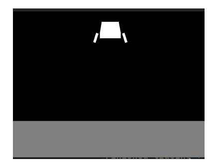
Implementing any type of self-play pipeline requires having a high-quality, high-performance simulator. This is done in JAX as inspired by Brax [16]. The simulator is currently a work-in-progress and presently supports only rigid-body collisions and a single environment, lunar lander. The GitHub repository for the simulator source code is available at https://github.com/DelftMercurians/cotix.
Conclusion & Future Work
As a first-time participant, the team had zero technical debt, so effort was put into exploring different and unique ideas. Not all ideas were feasible, but the learning experience was fruitful and the final design still implemented most of the team's innovations. It should also be noted that the team had only been active for over a year as of this report; the video demonstration submitted as the qualification material does not represent the final robot behavior. The team expects a full team of robots to be built to compete in division B with smooth motor controls and cooperative play.
Future work for the team mainly consists of completing the other necessary components for the robots such as the kicker and the chipper, improving the modularity of the motor drivers and the BMS, and continuing research into reinforcement learning aided strategies.
The current kicker PCB is based on that from TIGERs Mannheim [17], using only one 250 V 2.20 mF capacitor. However, this does not allow us to kick at the maximum allowed speed of 6.0 m/s. The plan is to double the capacitor, but this requires redesigning the kicker board as well as finding space to place the second capacitor.
The next version of the control electronics will consist of one main PCB that connects through a PCIe-like connector to the motor drivers and has connectors for the motor cables at the right places. This will reduce the amount and length of cables, which simplifies the design and makes connections more secure. Furthermore, a connector will be added for the encoder cables, ensuring the motors are also easier to replace.
To improve battery performance and safety, future iterations of the robot's power system will include a smart BMS. This subsystem will be placed on top of the robot since there is sufficient space and ventilation. Further investigation will be needed to determine if a more compact solution is commercially available to manage a 6S Li-Ion battery pack.
The next step for the smart strategy pipeline after the simulator is complete is to start training a reinforcement learning model. The intention is to use self-play to continuously improve the quality of the policy. While policy function is more readily available, the value function is much easier to incorporate into the MPC pipeline. Thus, alongside the policy function, the value function will be learned. Afterward, with iterative improvements in the quality of the value function, the overall control pipeline accuracy will improve at the same time.
Acknowledgements
We would like to express our deepest gratitude to the TU Delft Robotics Institute and BGlobal for their financial sponsorship and to RoboHouse for providing us with office space. Furthermore, we are also very thankful for the components we received from RS Components, Nanotec, GeT Cameras, and STMicroelectronics. We would also like to extend our sincerest thanks to TIGERS Mannheim, RoboTeam Twente, and ER-Force for their time and help in getting us up and running.
Lastly, thanks to all the members that have contributed to the paper and the team: Thomas Hettasch, Zhengyang Lu, Tim Verburg, Alexander Nitters, Nianlei Zhang, George Sotirchos, Leila Hashemi, Kevin Do Cao, Thijs Houben, Martijn Boonen, Kian Ebrahimi, Eçce Sinanoglu, Balint Magyar, Guillem Ribes Espurz, Teodor Neagoe, Yohan Le Gars, Renyi Yang, Matei Panzariu, Alexandru Lolea, Roman Knyazhitskiy, Ivan Lopez Broceño, Mikhail Vlasenko and Akansha Mukherjee.
References
- "Delft Mercurians," [Online; accessed 12. Feb. 2024]. [Online]. Available: https://delftmercurians.nl/about/
- P. Harrison, "More suck, less slip - Micromouse Online," Micromouse Online, Feb. 2018. [Online]. Available: https://micromouseonline.com/2018/02/18/more-suck-less-slip
- "My ProjectQ - Excel-9a," Jan. 2024, [Online; accessed 23. Jan. 2024]. [Online]. Available: https://sites.google.com/site/myprojectq/robotic/classic-micromouse/excel-9a
- "Micromouse," Nov. 2018, [Online; accessed 23. Jan. 2024]. [Online]. Available: http://greenye.net/Pages/Micromouse/Micromouse2015-2016.htm
- L. Bos, Y. Citgez, H. Dorenbos, A. Eichler et al., "Roboteam twente extended team description paper 2020," RoboCup Wiki as Extended Team Description of RoboTeam Twente Team, 2020.
- J. Almagro, H. Gynai, T. Jones, A. Khadse, C. Lindbeck, M. Maisonneuve, J. Neiger, R. Osawa, A. Siqueira, A. Srinivasan et al., "Robojackets 2020 team description paper," 2018.
- "Glitter 801B - Spot Welder," Feb. 2024, [Online; accessed 6. Feb. 2024]. [Online]. Available: https://glitterwelder.com/glitter-801b-battery-spot-welder-11-6-kw-capacitor-energy-storage-pulse-welding-machine-mini-portable-spot-welding-equipment-for-18650-14500-lithium-battery-pack-building/
- Epoch10650, "Epoch 18650 2800mah 40a battery (p28b)." [Online]. Available: https://www.18650batterystore.com/products/epoch-18650-2800mah-40a-battery-p28b
- "Test of Samsung INR18650-35E 3500mAh," Nov. 2023, [Online; accessed 18. Oct. 2023]. [Online]. Available: http://lygte-info.dk/review/batteries2012/Samsung%20INR18650-35E%203500mAh%20%28Pink%29%20UK.html
- A. Ryll and S. Jut, "Tigers mannheim extended team description for robocup 2020," Dec. 2020, [Online; accessed 5. Feb. 2024]. [Online]. Available: https://download.tigers-mannheim.de/release2020/ETDP_TIGERs_Mannheim_2020.pdf
- A. D. Neto, B. B. Correa, G. M. Schiavetto, G. SL, G. S. P. Agune, G. W. Cardoso, H. B. Simoes, I. R. Moscardo, J. V. Aguiar, L. d. S. Costa et al., "Robofei 2022 team description paper."
- A. Skuric, H. S. Bank, R. Unger, O. Williams, and D. Gonzalez-Reyes, "SimpleFOC: A Field Oriented Control (FOC) Library for Controlling Brushless Direct Current (BLDC) and Stepper Motors," Journal of Open Source Software, vol. 7, no. 74, p. 4232, Jun. 2022. [Online]. Available: https://doi.org/10.21105/joss.04232
- M. Eischer, P. Blank, A. Danzer, A. Hauck, M. Hoffmann, B. Reck, and B. M. Eskofier, "Er-force extended team description paper robocup 2015," 2015.
- M. Ito and Y. Ando, "Robodragons 2022 extended team description," 2022.
- T. M. Moerland, J. Broekens, A. Plaat, and C. M. Jonker, "A0c: Alpha zero in continuous action space," 2018.
- C. D. Freeman, E. Frey, A. Raichuk, S. Girgin, I. Mordatch, and O. Bachem, "Brax – a differentiable physics engine for large scale rigid body simulation," 2021.
- "TIGERs Mannheim Open-Source Electronics," 2020. [Online]. Available: https://github.com/TIGERs-Mannheim/electronics