GreenTea 2024 Team Description Paper
Hirotaka SATO, Naoyuki OKAMOTO, Akito ITO, Shun KAYAKI, Shoma NAKAAKI, Tomoki NAKAO, Yuki NISHIMURA, Yuto HARA, Kohei FUJITA, Rintaro YURI
The Open University of Japan; Graduate School of Informatics, Kyoto University; Faculty of Computer Science and Systems Engineering, Kyushu Institute of Technology; Graduate School of Engineering, Osaka Institute of Technology; Undergraduate School of Informatics, Kyoto University; Graduate School of Science and Technology, University of Tsukuba
Abstract GreenTea is a student organization founded in 2019. We will give an update on our robots since last year. In particular, we focus on our AI system, circuits, communication, and the local camera system installed on our robot itself. Also, we mention our contribution to the SSL community by conducting the video streaming of the RoboCup Japan Open. We look forward to seeing the robot in competition.
Keywords: RoboCup, small size league
1 Introduction
GreanTea is a team formed in 2019 by robot enthusiasts throughout Japan, regardless of the organization and location. Each member belongs to various organizations and has a diverse background, from student to worker. Each specializes in a different field, including electrical, mechanical, applied mathematics, robotics, informatics, regional innovation studies, acoustics, semiconductors, and cognitive science, and each makes the most of his strengths. We participated in the Japan Open 2022 and 2023 and submitted our TDP in 2023 [5]. Our robots have been updated about software and hardware, based on those described in TDP2023 [5].
In particular, we describe circuits and software, which were not described thoroughly enough in the TDP2023. First, we summarized our new challenge, our contributions to the SSL community, in Section 2. Then, the system of our AI and the embedded are described in the section 3 and 4. Finally, our challenge to install a camera on our robot is described in Section 5.
2 Contributions to the SSL community
2.1 Overview
Our team is not affiliated with a university or other organization, which allows us more freedom in our activities. Therefore, we focus not only on academic contributions but also on activities that can increase the number of participants and aspects of the conference that will make it more exciting. Here, we introduce our activities in 2023 from this perspective.
2.2 Video streaming of RoboCup Japan Open
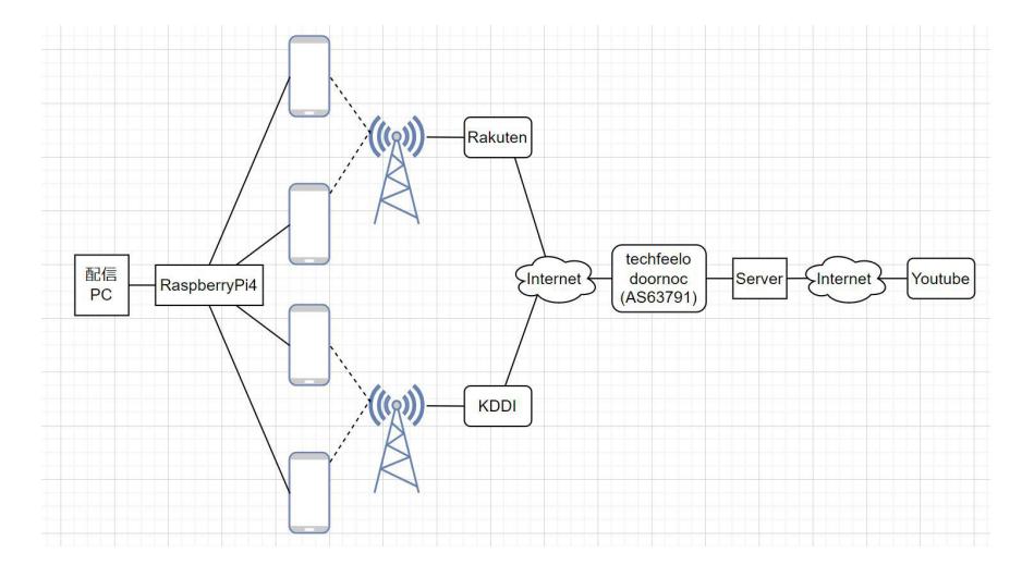
In Japan, a tournament called the Japan Open is held every year. This tournament is open to the general public so that anyone can watch the games at the tournament site. We have provided an environment in which anyone can view the competition beyond the physical constraints of the competition by streaming it online. These activities are expected to increase the tournament's visibility and attract new participants. However, the conference venues do not always provide a broad Internet environment in general, so our system used the OpenMPTCProuter OSS [6] to bundle multiple mobile lines and provide a stable environment by ourselves. The system is shown in Fig. 1. In addition, multiple cameras, switching and distributing, and play-by-play announcements provide high-quality content.
2.3 Outreach activity at Maker Faire Tokyo 2023
MakersFair Tokyo is one of the MakersFair, a competition for DIY enthusiasts, held annually in Tokyo. Our team had a stall at Makers Fair Tokyo and gave information about RoboCup, our robots, and elemental technologies to many people. We focused on outreach to the younger generation and provided an automatic goalkeeper robot, a manually operated shooter robot, and a penalty kick game.
3 AI System
3.1 Overview
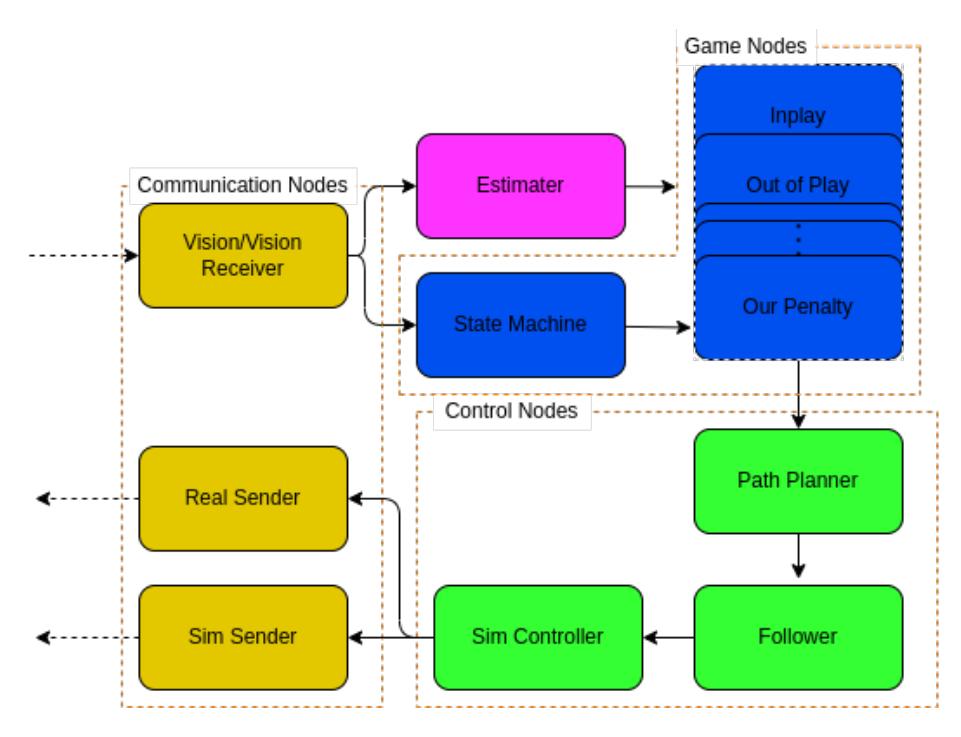
Our AI system is implemented using Robot Operating System (ROS), and its structure is organized as depicted in Fig. 2. The software architecture of our system outlined in our TDP in 2023 [5] continues to be employed. The subsequent sections provide in-depth explanations of elements that play a crucial role in decision-making.
3.2 Inplay Node
This section describes the Game Node corresponding to the inplay condition, referred to as the "inplay node". The inplay node is implemented as a ROS node, accompanied by ROS services for behavior generation and evaluation. Additionally, this node adopts the Skills, Tactics, and Plays (STP) architecture [2]. Assigning a role to each robot based on the game situation facilitates the realization of gameplay.
Roles In the tactics of STP, five distinct roles are employed, namely GK, DF, IC, AK, and MF. The GK, DF, and IC execute adaptive maneuvers corresponding to the position of the opposing robot, assuming defensive responsibilities. On the other hand, AK and MF collaborate to undertake an offensive role, steering the ball towards the opponent's goal.
- GK(Goal Keeper) obstructs an enemy team's shot in front of our goal.
- DF(Defence) interferes with the opponent's shot outside the penalty area.
- IC(Interceptor) interferes with the pass of the opponent team.
- AK(Attacker) holds the ball and shoots or passes the ball.
- MF(Mid fielder) receives passes from the AK.
DF constructs a wall in front of their own goal to obstruct the opposing team's shots, and IC disrupts passes of an opposing team. AK executes two distinct actions, namely passing the ball and shooting for the goal. By delivering passes to MF, AK works in tandem to advance the ball towards the opponent's goal.
The allocation of the number of robots to each role varies depending on the game situation and the positional relationships of opponent robots. The assignment of robot numbers to roles is determined by a rule-based algorithm grounded in the empirical rule.
Decision Making MF functions essentially as the receiver for passes in this system, and field areas are allocated based on AK's movements. MF waits within the assigned area to receive a pass, and AK selects one MF from those in waiting to deliver the pass. In the following, we will elaborate on the generation of MF positioning and the method for selecting the target MF for passes.
The allocation of regions in the field for MF is undertaken to maximize the minimum deviation angle from MFs positioned at AK possessing the ball. The deviation angle calculation employs the region's centroid as the representative point. Candidate regions for MF assignment are generated using a pre-designed rule-based system.
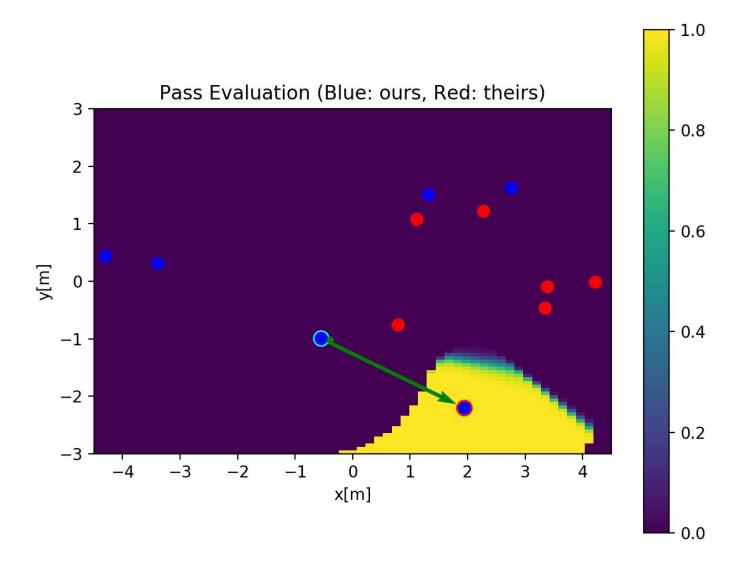
In the process of planning the pass action, AK selects the MF with the highest evaluation score to deliver a pass. The assessment of the MF involves the product of the evaluation of the MF's receiving action and the evaluation of the receiving position. By decomposing the evaluation of combinations in this manner, it becomes possible to eliminate regions with lower evaluation scores in advance.
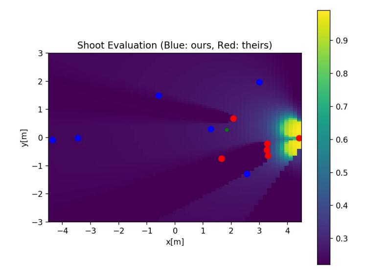
The evaluation of the receiving action incorporates information such as the position of the opposing team's robots and the distance from AK. The evaluation of the receiving position is to represent the preference of shooting from the position, and takes into account factors such as the deviation angle concerning the goal and the position of the opposing goalkeeper. Specific numerical examples are presented in Fig. 3 and Fig. 4.
In the future, we are considering incorporating the use of Softmax to select the target for passes probabilistically, as well as exploring the application of bandit problem algorithms to choose the pass target adaptively.
4 Embedded
4.1 Main Board
The main board interprets commands wirelessly received from the AI and sends appropriate commands to each component within the robot, such as motor driver and kicker driver. This section will explain the circuit of the newly designed main board.
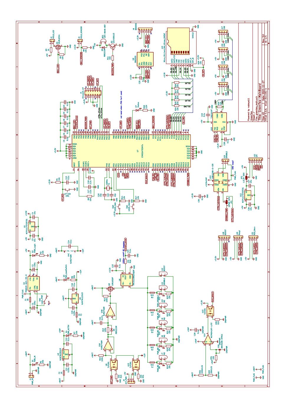
Fig. 5 is the circuit design of the main board. There is no inverse connection protection, trusting our team members. The required power supplies are battery voltage for motor drive, 5V for a Raspberry Pi drive, and 3.3V for the microcontroller. A Pch-MOSFET is used for ON/OFF of the motor power supply to share the same GND. Since the battery voltage cannot be used as it is due to the maximum voltage of G-D, a -12V power supply is generated by a regulator based on the battery VCC. CUI's PDQE20-Q24-S5-D was used as a 5V output DCDC (available even under severe supply flow due to COVID-19) and can supply a total of 4A, including Raspi. Passive elements around it follow the DCDC datasheet. To reduce the inrush current to the MD, a low-pass filter R13 and C21 are used to slow down the rise of Q3 (Pch-FET), and U4 (operational amplifier) is used as a voltage follower. On the other hand, the current should decay quickly after disconnection, so D6 is connected in parallel to R13. U8 is a current sensor. The kicker booster board marked "BOOST" has a safety circuit on the board side, while the others have fuses on the main board for safety. We considered using a microcontroller to monitor the battery voltage directly, but obtaining an ADC with isolation was difficult. Therefore, a comparator is used to set 3.7Vx4 as the threshold, and a High signal is sent to the microcontroller when the voltage falls below the threshold. The buzzer expresses the robot's status through melodies. The microcontroller is inherited from the previous generation of the main board. An SD card is connected to the microcontroller via SDIO to save the debug log quickly. The motor driver communicates via CAN, using only one bus. Since there were two types of dribbles, the current ESC that communicates via PWM and a board that communicates via UART, which was being considered for adoption, a short pattern was placed to accommodate both. SPI connector is available as an option.
4.2 Communication
In our team, we deploy Wio Terminal on robots to receive commands from AI via WiFi [5]. Currently, commands are received via UDP Broadcast. However, we have observed differences in the robot's behavior when receiving commands in UDP Broadcast mode compared to UDP Unicast mode (see experimental video [4]).
Upon measuring delays, we found that receiving commands through Broadcast results in a delay of approximately 100ms, whereas with Unicast, the delay is around 10ms. To isolate the cause, we replaced Wio Terminal with a different travel router (TP-LINK TL-WR902AC), and even in the case of Broadcast, the delay was only about 8ms.
Therefore, it became evident that the issue of significant delay with UDP Broadcast is specific to Wio Terminal. In the future, we plan to either change the wireless module used for reception or adopt UDP Unicast.
5 Local Camera System
In SSL, the Vision system provides the AI system with information about the positions of the robots and the ball. However, this information has relatively low time resolution and some latency. This drawback is critical, especially for the ball position, because it moves fast. This section describes how we are trying to solve this problem by installing the camera on the robot itself.
5.1 Overview
The local camera system estimates the ball position and has two main components: ball detection and coordinate transform. The ball detection process follows the implementation [3]. The procedure of the ball position estimation is summarized as follows:
- Obtain a frame from the camera
- undistort the frame
- obtain the "orange-ness" image
- detect the ball and estimate the position on the screen coordinate
- transform the position to robot coordinate
5.2 Ball Detection
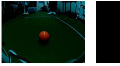
Hardware settings The camera used for the system is Raspberry pi camera (g) with the image sensor OV5647. The camera was processed using a Raspberry Pi 4B. The camera was installed to look down on the ground from the top of the robot's front surface.
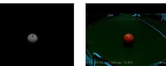
The Color Space We use the YCbCr color space to effectively emphasize the contrast of the orange ball on the green field, following the original implementation [3]. The color comprises one luminance signal and two color difference signals (Cb, Cr). By calculating the difference between these two color difference signals, a gray-scale image with "orange-ness" can be obtained(Fig. 6). We clip the negative value of the gray-scale image to zero because the white line on the green field was also detected during the edge detection.
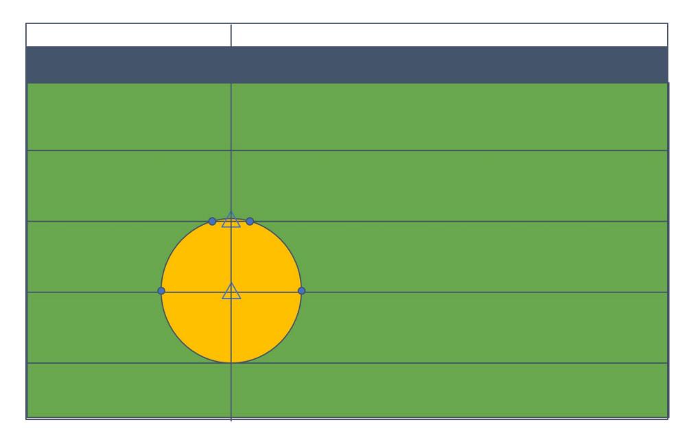
Detection Process Fig. 7 shows how to detect the ball. The system is given several scanning lines in the X-axis direction in advance, calculates the derivative of the gray-scale image along the X-axis direction on the scanning lines, and detects edges. The center position in the X-axis direction is calculated from the edge positions detected on each scan line. At each center position, a scan line in the Y-axis direction is drawn, edges are detected similarly, and the center position in the Y-axis direction is calculated. This yields multiple estimates of the ball center, which are averaged to obtain a single estimated point.
5.3 Coordinate Transform
The estimated points obtained are the screen coordinates. Therefore, a coordinate transformation is performed to convert them to the robot coordinates [1]. However, converting from the screen coordinates to the robot coordinates is an ill-formed problem. Thus, we introduced the constraint that the z-coordinate (height) of the ball in the robot coordinates is always rb, the radius of the ball.
First, we show the forward conversion from the robot coordinates to the screen coordinates below.
$$\begin{pmatrix} x' \ y' \ z' \end{pmatrix} = R^{-1} \left( \begin{pmatrix} x \ y \ z \end{pmatrix} - \begin{pmatrix} t_x \ t_y \ t_z \end{pmatrix} \right) \tag{1}$$
$$\begin{pmatrix} u \ v \end{pmatrix} = \begin{pmatrix} f_x & 0 \ 0 & f_y \end{pmatrix} \begin{pmatrix} x'/z' \ y'/z' \end{pmatrix} + \begin{pmatrix} c_x \ c_y \end{pmatrix}$$ (2)
where (x, y, z) is the ball position in robot coordinates, (x ′ , y′ , z′ ) is the position in camera coordinates, (u, v) is the position in screen coordinates, (tx, ty, tz) is the camera position in robot coordinates, R is a rotation matrix indicating camera orientation from the robot coordinates, fx, fy is the focal distance in pixels, and (cx, cy) is the image center. The calibrateCamera function of OpenCV returns the camera matrix
$$\begin{pmatrix} f_x & 0 & c_x \ 0 & f_y & c_y \ 0 & 0 & 1 \end{pmatrix}$$
Based on the above, we consider the inverse transformation from the screen coordinates to the robot coordinates. Since screen coordinates are two-dimensional, the z axis in robot coordinates cannot be determined. Therefore, we solve the transformation assuming z ′= s.
$$\begin{pmatrix} x' \ y' \end{pmatrix} = z' \begin{pmatrix} f_x & 0 \ 0 & f_y \end{pmatrix}^{-1} \begin{pmatrix} \begin{pmatrix} u \ v \end{pmatrix} - \begin{pmatrix} c_x \ c_y \end{pmatrix} \end{pmatrix} = s \begin{pmatrix} f_x & 0 \ 0 & f_y \end{pmatrix}^{-1} \begin{pmatrix} \begin{pmatrix} u \ v \end{pmatrix} - \begin{pmatrix} c_x \ c_y \end{pmatrix} \end{pmatrix} \quad (3)$$
$$\begin{pmatrix} x \ y \ z \end{pmatrix} = R \begin{pmatrix} x' \ y' \ z' \end{pmatrix} + \begin{pmatrix} t_x \ t_y \ t_z \end{pmatrix} = R \begin{pmatrix} x' \ y' \ s \end{pmatrix} + \begin{pmatrix} t_x \ t_y \ t_z \end{pmatrix}$$ (4)
The resulting (x, y, z) is a function of s. So you can extract the equation of z as z = f(s). Because of the constraint z = rb, s is uniquely determined,
$$z = r_b = r_{31}x' + r_{32}y' + r_{33}s + t_z, (5)$$
$$\therefore s = (r_b - (r_{31}x' + r_{32}y' + t_z)) / r_{33}$$ (6)
Now, s can be calculated first based on the equation 6, and (x, y, z) T is determined afterward following the equation 4.
The robot's posture and position information can be obtained from Vision, which enables conversion of the robot coordinates to world coordinates. This estimated ball position will provide the robots with faster and more precise information than the Vision system and be used to complement the control from the AI.
References
- Camera calibration and 3d reconstruction. https://docs.opencv.org/2.4/modules/calib3d/doc/camera_calibration_and_3d_reconstruction.html
- Browning, B., Bruce, J., Bowling, M., and Veloso, M. Stp: Skills, tactics, and plays for multi-robot control in adversarial environments. Proceedings of The Institution of Mechanical Engineers Part I-journal of Systems and Control Engineering 219 (12 2004).
- Fabio Seel, and Sabolc Jut. On-board computer vision for autonomous ball interception. https://download.tigers-mannheim.de/papers/2019-BallIntercept_TC-Seel_Jut.pdf, 2019.
- GreenTea-SSL. experiment 2023 06 17 broadcast and unicast. https://youtu.be/OkgY2Ra6FrQ.
- Sato, H., Okamoto, N., and et.al. Greentea 2023 team description paper.
- Yannick Chabanois. Openmptcprouter. https://www.openmptcprouter.com/. Accessed: 2024-4-1.