ICRS-FC Team Description Paper
Jingchuan Liang, Ben Smith, Fred Huang
Imperial College London Exhibition Rd, South Kensington, London SW7 2BX UK
https://github.com/ICRS/SSL-2024
Abstract This paper describes the efforts by ICRS FC to develop hardware and software capable of competing in the Robocup Small Size League. Since this is the first time ICRS FC has attempted to compete, the focus was on achieving a minimum viable robot, including movement, dribbling, kicking, and software systems that can be improved upon before the competition, and into future years.
1 Introduction
ICRS FC is a new team formed in September 2023 from members of the Imperial College Robotics Society (ICRS). Several members had previously attempted to compete in the Robocup Middle Size League, but due to the resources required and small team size, it was decided to focus on the Small Size League instead. This paper is split into sections focusing on the mechanical, electrical, and software implementations and challenges.
2 Mechanical Systems
2.1 Mechanical System Overview
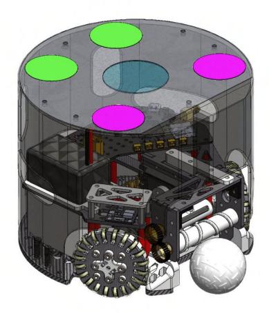
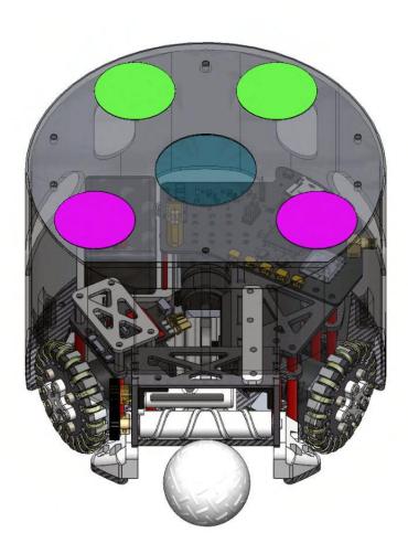
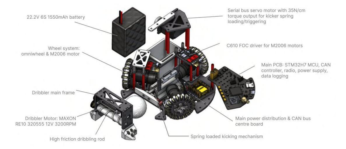
The mechanical system is the core on which all the other systems depend. As such it needs to be able to perform responsive and precise maneuvers and effective ball manipulation. As we are a new SSL team with no prior experience, the goal of the 2024 season is to quickly catch up with other teams' completeness under a constrained time frame and budget. Figure 1 shows the complete assembly of our SSL robot design.
The overall mechanical system is divided into two sections: the drive base and ball control, which are elaborated on in sections 2.2-2.3.
2.2 Drive Base Design Objectives
Given the size limitation and required functionality, we have established the following principles for the drive base design, which include the wheel system and chassis frame:
- Overall lightweight and and rigid: enables fast movement and can withstand high impact forces.
- Modularity: assemblies of parts can be decoupled from the system easily. This enables fast identification of problems and replacement of faulty components.
- Since the drive base was developed at the early stage of the entire project, enough expandability needs to be ensured to accommodate parts developed afterwards.
2.3 Wheel System
A wheel system consists of an actuator, gearbox, feedback encoder, motor mount, and output wheel.
Wheel Design
Mecanum wheels and omniwheels are common methods that use velocity vector superposition among different wheels to achieve 3DOF omnidirectional motions. We chose omniwheels as they better fit the circular chassis. A common offthe-shelf omniwheel (Figure 2) has the following limitations:
- Large thickness and shaft connectors occupies too much space.
- Inconsistency of roller curvature causing high amplitude vibration to the chassis
- Too expensive more than £20 for each wheel
Therefore, inspired by the eTDP from ZJUNlict, we proposed our own omniwheel design with several improvement, which is shown in Figure 3.
In our wheel design, a H3D8 ball bearing coated with 1mm polyurethane rubber layer makes up a single roller unit. This is thin enough which allows us to fit 20 rollers in a 53mm circular array. A dull pin and two thin washers are used to ensure the smooth and robust rolling. The whole roller array is sandwiched between a 3d printed PETG wheel mount and carbon fibre plane. The outer carbon fibre plane connects directly to the motor shaft, which has excellent torsional rigidity for the wheel structure. Each mentioned component can be manufactured/bought cheaply, which lower the price of each wheel to £4.
Motor Selection
Although traditional DC brushed motors can be actuated and controlled easily (using PWM and H-bridge), a brushless motor, facilitated with FOC (Field Oriented Control) driver and feedback encoder has much better performance in terms of speed, position and torque control.
In addition to maximum angular speed ωmax and continuous maximum torque τmax, motor size and proper communication protocol are crucial criteria for motor selection. Integrating a planetary gearbox within the omniwheel enhances τmax but increases maintenance and assembly difficulty.
After careful consideration, we chose the RoboMaster M2006 P36 motor and C610 controller for our drive base. This system features a 36:1 planetary gearbox and a built-in encoder providing position, angular velocity, and torque feedback. Mechanical CAD and motor specifications are shown in Figure 4.1 and Table 1, respectively. Communication between multiple motors and MCUs is established using the CAN bus protocol, enabling minimal wiring and stable differential signal transmission across nodes (schematic shown in Figure 5).

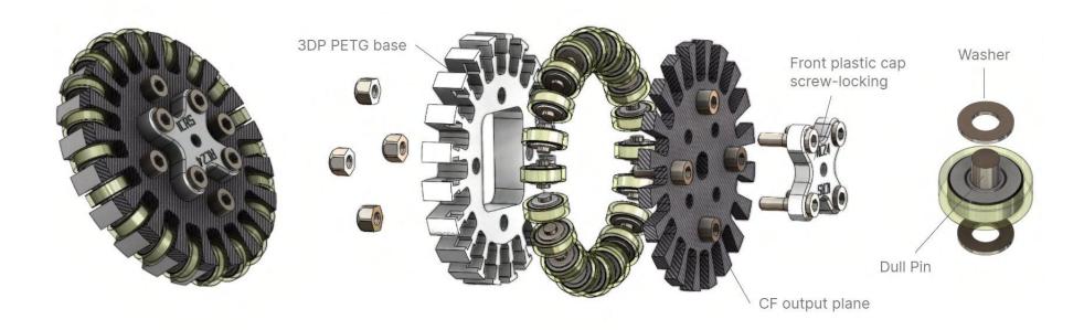
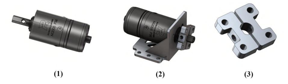
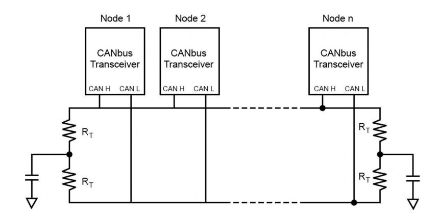
Table 1. Specifications of M2006 & C610 motor system
| Variable | Value |
|---|---|
| ω (unloaded) | 500rpm |
| Current (unloaded) 0.6A | |
| τmax | 1N · m |
| Max current | 3A |
| ωτmax | 416rpm |
The motor shaft connector and base mount were also carefully designed for manufacturing processes. The output shaft mount requires rigidity and tight installation while minimizing occupied space. We devised a two-piece hugging mechanism tightened with a penetrated M3 screw (Figure 4.2 & 4.3). Using SLA 3D printing and aluminum alloy for manufacturing proved cost-effective due to their small size, low height, and simple geometry, compared to traditional 3-axis CNC. The parts were annealed, and the shaft connector's front holes were threaded for a more compact structure and easier wheel disassembly.
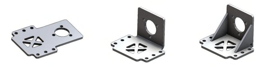
The motor mount, made from sheet metal, utilized a 2mm 6061 aluminum alloy sheet bent 90 degrees to hold the motor, with triangular supports welded on for strength (Figure 6). This approach ensured a compact and easily fixable wheel system.
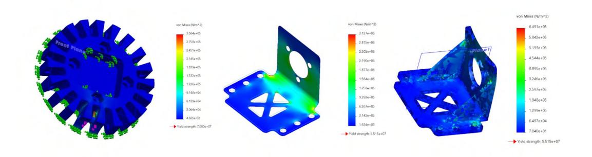
Finite element analysis was also performed on the 3D printed wheel shell and motor mount before the manufacturing stage to ensure no significant deformation or fracture would happen.
2.4 Chassis Frame Design & Layout
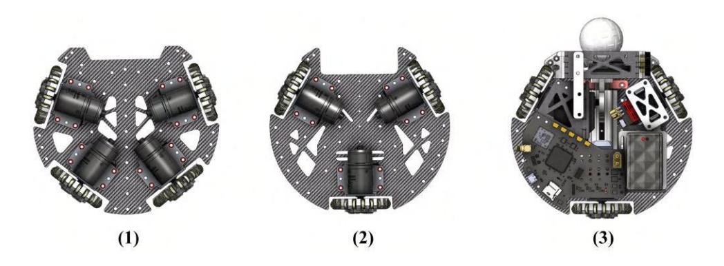
As the wheel system is modularised, we carried out 2 chassis configurations to see which one better fits our objective (Figure 8.1 & 2). The 4 wheel design could reserve more space in the centre for the kicker, however, as the motor is relatively long, the reserved space is still quite limited (This is something worthy to improve by integrating the planetary gearbox to the wheel in the future development). We ultimately selected the 3 wheel configuration for budgeting reasons and the overall structure breakdown is shown in figure 9.
We choose to use threaded aluminium pillar extended from the motor mount to establish a upper platform to install peripheral structural components and electronics. The rest of the space on the base is reserved for battery, cable management, kicker and dribbler. The two ball control modules are explained below.
2.5 Ball Control
Kicker
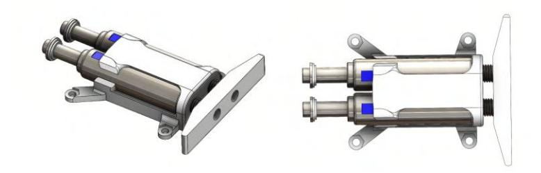
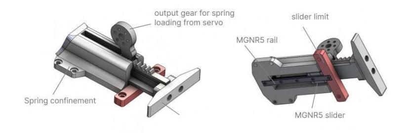
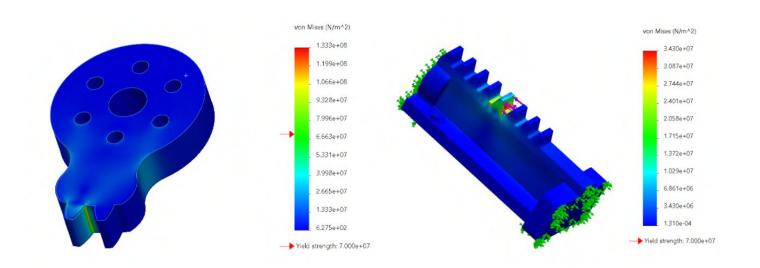
We implemented two types of kicking mechanism in parallel to see which one performed better. One is to have two compact 24V solenoids push the kicker cap in parallel (Figure 10), the other one is to use a spring loaded mechanism. The former has a much simpler structure than latter, and its structure is shown in Figure 10. The solenoids are triggered using a MOSFET on the main PCB. However, the force of impact these solenoids produce, under its standard rating at 24V 0.85A is not high enough. Based on the existing experiment, approximately the ball can be accelerated only by $0.8 \text{ m/s}^{-2}$ after impact. A dedicated power supply board with capacitor for fast discharge rate can be further developed in order to satisfy the competition requirement. The other spring loaded mechanism is still under development and has not been tested yet (Figure 11). The goal is to convert elastic potential energy into kinetic energy. A spring is confined in a 3d printed shell to prevent buckling during compression, and the motion of the kicker is constrained to linear by installing it onto a miniaturised slider. The spring is loaded by a high torque servo motor, and the stress analysis for the output gear and rack has been performed in figure . Both of the gear and rack are 3D printed using PETG, and results (Figure 12) have shown acceptable stress and deformation level at the gear.
Dribbler
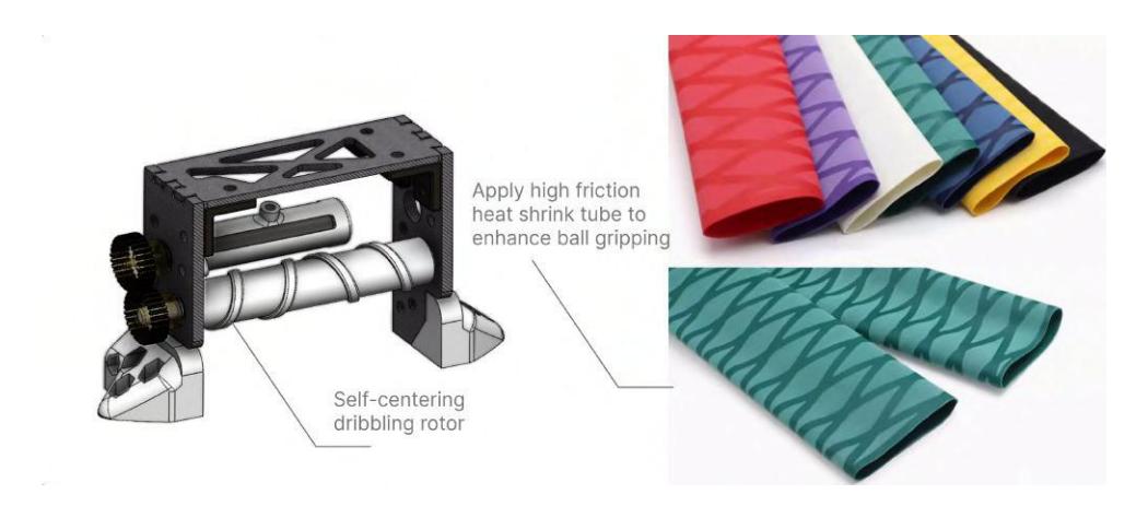
We choose to employ a traditional dribbler structure as our first generation design and it is shown in figure 13. The rotor in contact with the ball is installed rigidly between two flange ball bearings mounted on the carbon fibre frame, and it is driven by a MAXON RE10 320555 motor, which provides adequate torque and high speed to maintain the dribbling motion. The rotor was design with symmetric helical pattern bump that allows the ball to be self-centred during dribbling. We choose to seal the rotor in high friction heat shrink tube to make its surface texture more grippy and softer, which could absorb shock energy when the ball is passed to the dribbler, and increase the coefficient of friction to produce a more stable rolling motion.
3 Electronics
The approach with the electronics was to individually verify each subsystem, and then integrate them all into a printed circuit board (PCB) to save space and weight and increase the reliability of the system.
3.1 Micro-controller
The amount of processing required by each robot is relatively small, and as such only a microcontroller is required (as opposed to a single board computer like a Raspberry Pi). The use of a microcontroller also gives low level control and accurate timing over the hardware. Multiple tasks such as radio communication, control loops and sensor sampling and processing can be run in parallel using a real time operating system (RTOS). The microcontroller selected for this purpose was an STM32H7 due to its powerful Arm Cortex M7, rich set of peripherals, and team members having previous experience using them.
3.2 Wireless Conmunnication
Due to the restrictions on wireless communications, it was decided initially to use NRF24 modules with PCB antennas. These modules transmit at 2.4GHz and can use up to 126 non overlapping channels. By connecting two STM32 Nucleo boards to NRF24s via SPI, it was found that a range of up to 50m indoors through two walls could be reached, in a building with lots of other devices transmitting at 2.4GHz. Due to these promising results, it was decided to proceed with this module. If more transmission power is required, the modules can be connected to power amplifiers and active antennas.
3.3 Battery
We had to find a small battery that was able to power our robots at 24V with a decent runtime at the lowest cost possible. Therefore, we used a 1550mAh 6 cell lipo battery that was able to fulfill these criteria. We intentionally chose one with a high discharge rating of 100C so that it will be able to easily power the three M2006 motors and solenoid at max speed, allowing us to accelerate fast if we needed to. We also made a trade-off between the capacity and dimensions of the battery, with an estimated run time of 30min due to its small size (72x35x57mm). However, this is more than sufficient to power the robot for what we need it to accomplish.
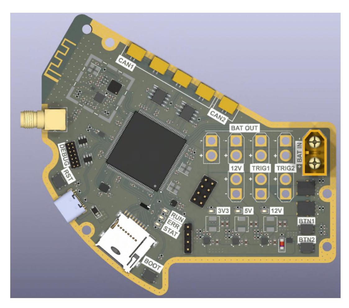
3.4 PCB
The PCB was then created to integrate all the subsystems. Features include:
- 3.3V, 5V and 12V rails
- CAN and power connectors for motors
- 6DoF IMU and magnetometer
- SD card slot for data logging
- STM32H723 microcontroller
- NRF24L0+ wireless transceiver
- Buttons
- GPIOs
- LEDs
4 Software
4.1 grSim
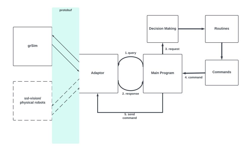
Without initial access to any hardware to test decision-making software, it proved advantageous to use grSim (Monajjemi, Koochakzadeh, and Ghidary) to simulate the SSL environment. It provides a similar interface to the shared vision system, using protocol buffer to serialize its outgoing messages and incoming commands. As a result, all routines have been written in grSim and will be ported to work with the vision system and physical robots. The flow of data in the current system from grSim packets to grSim commands is depicted below along with how it can be adapted to actual hardware.
The adaptor unpacks protobuf serialized classes and translates them into lightweight, read-only representations of the game state. Based on this state, the decision-making algorithms decide the appropriate routines, such as shooting, breaking away, or defending. With these routines and states, a command is generated for each individual player, describing the next step to carry out its given routine. This is translated by the adaptor to serializable data and communicated back to grSim. For efficiency, each piece of the pipeline is written in C++.
4.2 SSL-Vision & Communication
When we originally looked into ssl-vision we as a team looked into its auto colour calibrator, trying to understand how it performs robot and ball detection and where the confidence value comes from. we discovered a noticeable amount of noise that could arise during the competition especially when we start implementing the robots IMU's and its motors requiring cross validation with the vision system.After some research we found that there are teams that use certain filters like Kalman filters [3] to try and reduce the affects of the noise during game time and improve software and hardware communication.
4.3 Robot Control
Due the robot's capability to move omnidirectionally the control loop for the robot needs to be altered so that the velocities given to each robot will move them on the global x and y plane in order to take advantage of its versatility. As a result, our team were looking into ways to create an algorithm that maintains the orientation of the robot in the direction of the ball when the enemy has possession of the ball to create more opportunities for interception, resulting to a counter attack.
for motion planning we will be using RRT* for path generation as one of the main algorithms for decision making.
References
- ZJUNlict Extended Team Description Paper https://ssl.robocup.org/team-descriptionpapers/
- Monajjemi, V., Koochakzadeh, A., Ghidary, S. S.: grSim RoboCup Small Size Robot Soccer Simulator, RoboCup (2011)
- Kalman Filters https://en.wikipedia.org/wiki/Kalman_filter