OrcaBOT Team Description Paper 2024
Tongthai Thongsupan, Ned Sureechainirun, Warit Yuvaniyama, Athit Tantipjitkasem, Piyamin Sripho, Siriyakorn Sucharitjivavongse, Julathit Chetsawang, Phisitphon Pruksorranan, Kaweewat Sricharoenchit, Nuttaat Sricharoendhum, Pramat Anuntanasarn, Pakorn Limpornchitwilai, Nipparn Penjinda, Natthaphak Suesakulchockchai
Sirindhorn International Institute of Technology, Thammasat University, Rangsit, Thailand
https://siit-robocup.netlify.app/
Abstract This paper describes the details of the proceeding Small-Sized League robots from the second-generation OrcaBOT team. This year TDP, the team will prioritize the feasibility and stability of the robot, to improve and fix non-fulfillment from the first-generation team, from mechanical and electrical design that focuses on down-scaling the components to new communication and strategy in software.
1 Introduction
OrcaBOT has debuted in Small-Size-League Robocup 2023, Bordeaux. The team has gained valuable experience and found several areas for improvement. The second-generation team has undergone significant changes across many areas.
Mechanically, the most significant change involves the dribbler mechanism, changing from a 90-degree by 90-degree configuration to a new design with a 26.5-degree horizontal axis orientation. Electronically, the core processing unit of the new main board remains the Arduino DUE with major changes in motor drivers and kicker circuits. Low-level software continues to utilize pySerialTransfer while redesigning the system to be more optimized. High-level software has implemented simulations to enable better strategy testing within our software development process.
2 Mechanical Design
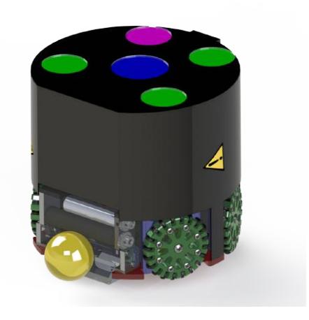
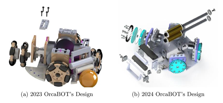
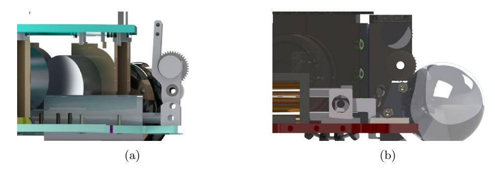
This section of the paper will illustrate our modifications to the mechanical structure concerning any citation applied to our team's policy and strategy. As shown in figure 2, 2024 OrcaBOT's mechanical design has changed significantly in all aspects, such as robot structure, dribbler, kicker, gearbox, and wheel.
2.1 Motors Specification
As for this year, we used 10-bit precision control Maxon EC45-flat motors, which have a resolution of 1024 steps[2], as driving motors with specifications as in table 1. While the specifications did not differ much from last year's motors (Nanotec DF45L024048-A2), we use the Maxon DEC 24/2 digital brushless amplifiers to drive the Maxon motors. We used Skywalker V2 40A ESC the previous year to control the motors with Arduino using the Servo.h library, capable of 180 steps (120 steps in practice), which precision cannot achieve our satisfaction. Additionally, the Servo.h library induces a small delay for each motor drive, which results in unwanted motor desynchronization added to the overall error. With the new amplifiers, we developed our own Arduino library to drive the Maxon motors with an 8-bit digital potentiometer, which yields greater accuracy of up to 256 steps based on the capability of the potentiometer.
Table 1: Specification of Maxon EC45-Flat Motors for Robot Wheels and Maxon EC16 Motor for Robot's Ball Dribbler.[3]
| Specification | Maxon EC45-Flat | Maxon EC16 Motor |
|---|---|---|
| No. of Pol/Phase | 8/3 | 1/3 |
| Nominal Voltage (V) | 12 | 12 |
| No Load Current (mA) | 163 | 397 |
| Nominal/Stall Current (A) | 2.02/10 | 3.41/29.8 |
| Terminal Resistance (Ω) | 1.2 | 0.403 |
| Terminal Inductance (mH) | 0.56 | 0.0235 |
| Nominal/Stall Torque (mNm) | 55/255 | 7.85/75.5 |
| Torque Constant (mNm/A) | 25.5 | 2.54 |
| Power Rated (W) | 30 | 30 |
| Nominal/No load speed (RPM) | 2940/4370 | 39300/44500 |
| Rotor Inertia (g · cm²) | 92.5 | 92.5 |
| Weight (g) | 75 | 75 |
2.2 Core Structure
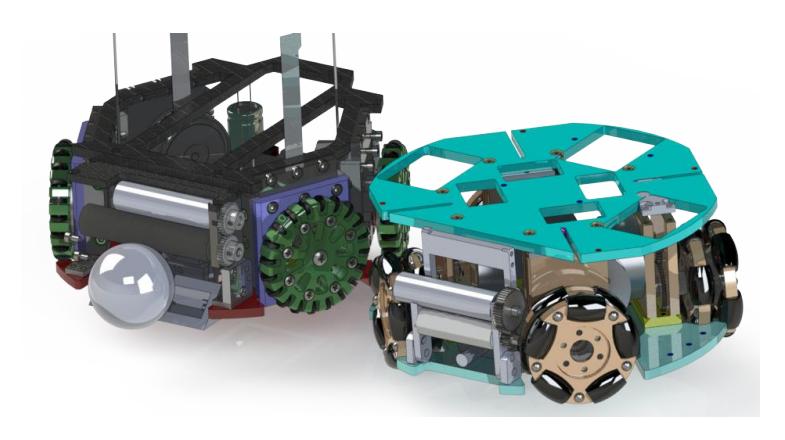
The overall structure of the robot is the same. However, the 90◦ configuration base used by the OrcaBOT team in 2023 (ϕ = 45◦ ) is changed to a 128◦ configuration base (ϕ = 26.56◦ ) while retaining the same functionality, like robot stability and movement along with the new motor and wheel design provide more available space, to accommodate electronic components. The design used by OrcaBOT in 2023, the motors are positioned very close to each other, causing noise interruption created by magnetic fields generated by another motor close by, causing discontinuous rotation. For the 2024 OrcaBOT team's design, the first floor consists of a dribbler, two solenoids, and four motors are anchored to the motor-base plate that supports the second floor, as shown in figure 2. Moreover, a motorbase plate is also used to lock the second floor in place and make it sturdy. The second floor and third floor (PCB) are mainly for the electrical circuits and battery placement. Poles grounded on the second floor provide support for the PCB on the third floor. We changed the structure materials from aluminum to PLA because of the ease of prototyping, repairing, and reducing costs.
2.3 Wheel Mechanism Redesign
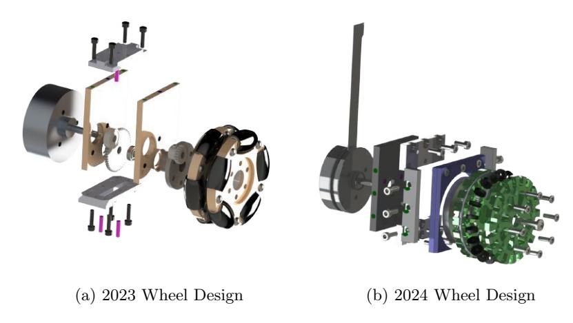
For the wheels, we have chosen omnidirectional wheels to allow free movement in all directions. However, the wheel design used by the 2023 OrcaBOT team as shown in Figure ?? turns out to be too thick, expensive, and has poor traction. As a result, the current wheel design, as shown in Figure 4b, will be redesigned to fix these issues. We used PLA as the material for the wheel body and subwheels. We changed the transmission design from a pinion-pinion connection to a pinion and ring gear with a ratio of 11:30, where the pinion is the driver gear, based on the Skuba team's design[7] in 2010. This will provide the wheel with more torque and more precise movements. In addition, with the new design, the motor base plate and wheels are smaller than the design used by the previous year's team, increasing space for other components, as mentioned in the core structure part.
2.4 Ball Dribbler
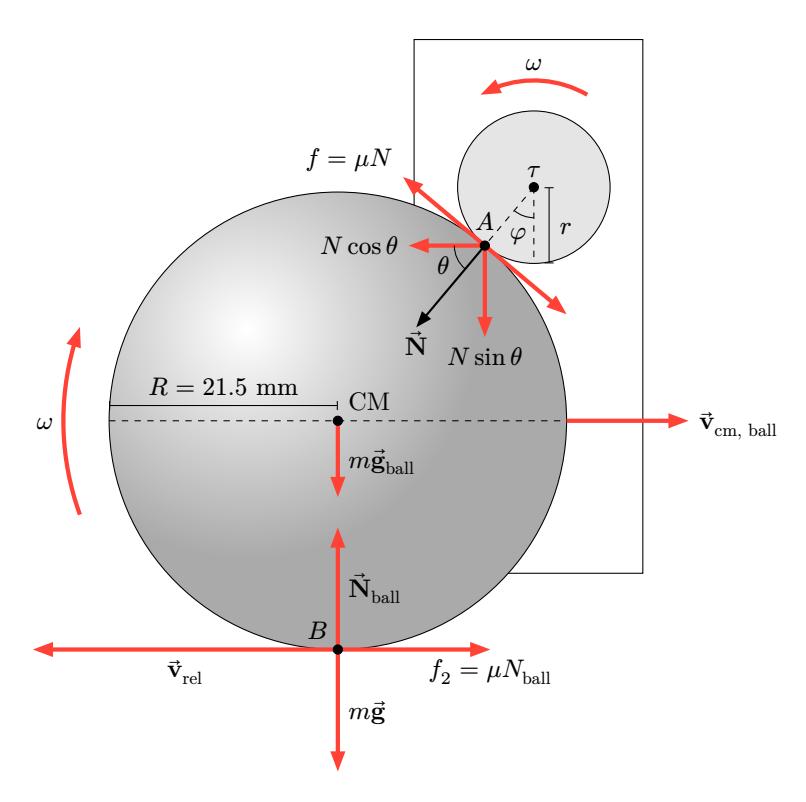
The redesign of the dribbler is based on force analysis on the free body diagram [5], which is shown in figure 6 and also expressed as equations by representing the forces acting on the ball during its movement as equations 1 and 2. To be more efficient, we have also set the conditions to satisfy the function of the condition on point A in figure 6, which is a contact point between the roller and the ball that must be rolled without slipping when the roller catches the ball. The condition to satisfy rolling without slipping can be expressed as equations 1 and 2.
$$\sum F_x = N\cos\theta - N_{\text{ball}}\mu - \frac{\tau}{R} = 0 \tag{1}$$
$$\sum F_y = N\sin\theta - N_{\text{ball}} = 0 \tag{2}$$
$$v_{\rm cm, \ ball} = R\omega \tag{3}$$
$$a_{\rm cm, \ ball} = R\alpha \tag{4}$$
Where Fx and Fy in the first and second equations represent the forces acting in both the X-direction and the Y-direction, respectively, while τ represents torque. Moreover, in equations 3 and 4, the radius of the ball is numerically represented by R, while the radius of the roller is r. For the angular acceleration and angular velocity, they are presented by α and ω, respectively.
According to this analysis, we decided to design a new dribbler with a semiadjustable type that can move up and down to use robot weight to generate the vector force on the ball, as can be seen in the analytical free body diagram 6. Both the 2023 and the 2024 designs share the same idea but in different ways, as can be seen in fig. 5. For the 2023 model, we use a revolute dribbler to rotate and move, respectively, the approaching force from the ball. For the 2024 model, the slot mechanism is applied to use the robot's weight as a force vector point on the ball.
2.5 Solenoid
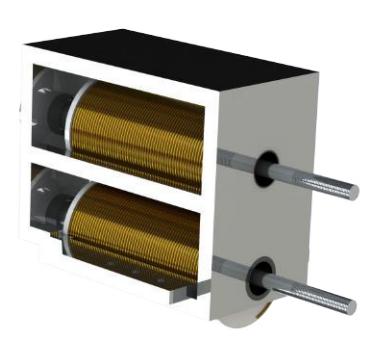
We used a solenoid in the market and replaced its original housing with a doublelayer housing solenoid as shown in figure 7. The upper solenoid will pull the chip to chip up the ball. The lower one will punch the ball directly.
3 Electronic Design
(continued below)
3.1 Main Board Design
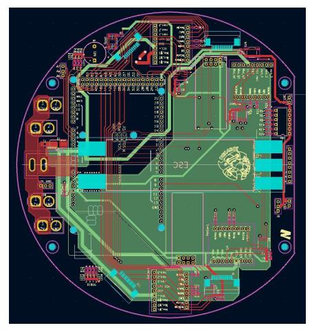
The board design architecture is based on the same idea as last year, using Arduino DUE as the core processing and control unit. However, the motor controller is different from the previous year's design. DEC 24/2 is the choice for this design. This particular module can be used with the Maxon EC45 and has a resolution of 1024 steps, which is higher than the ESC used in the previous year with only a resolution of 180 steps.
3.2 Kicker Circuit
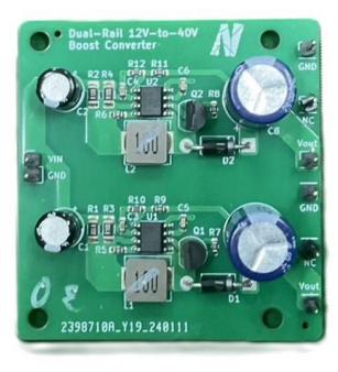
The kicker circuit is the most challenging design part of all the parts. So, the priority of the design is to make it capable of pushing the ball forward. The team decided to start with a step-up boost circuit before connecting it to an external capacitor capable of charging the capacitor as fast as possible. In the previous year, an Arduino Nano was added to the kicker circuit to be a node for kicker control, as this Arduino module uses a logic voltage level of 5 Volts. However, the circuit experienced a fetal failure on overvoltage, causing the MOSFET to burn. For this year's prototype, the team decided to remake the kicker circuit using MC34063A in figure 9, which is capable of step-up 12–40 Volts as the experimental version based on open source and connected to the main control board, making it easier to control.
4 Software
(continued below)
4.1 System Overview
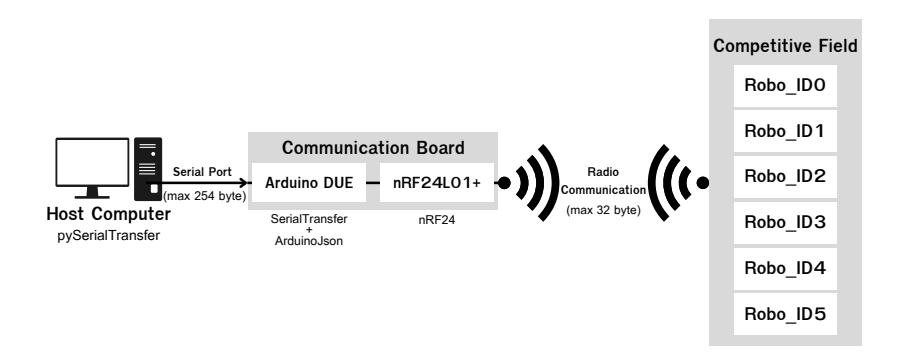
The systems responsible for the robots' actions comprise a high-level decision system and a low-level communication-control system. The high-level system is a group of software that takes input from field cameras and computes actions for each robot in the field. Starting from the camera, we set up and calibrated our camera to be compatible with the open-source SSL-Vision software. Subsequently, SSL-Vision sends the captured data from the field to the strategy software, which will decide the best possible course of action for each robot. After the strategic software has initiated the action-related decisions, the data will then be encoded into a Python dictionary and sent to the communication system using our pySerialTransfer-based software, which further encodes the data to JSON format and transfers it to the Arduino communication board through a serial port. The communication board then deserializes and packetizes the data and sends it individually through radio to each robot address using the nRF24L01+ module.
4.2 Low-Level Design
(subsections follow)
Communication
(Analysis of 2023 system follows)
Analysis of 2023's Communication System
Being a first-time participant in SSL-Robocup in 2023, due to limited manpower and time constraints, the communication system was not the main focus during software development. This resulted in a suboptimal communication system with compatibility issues between hardware and software. In 2023's communication system, we used pySerialTransfer library to send robot data (robot ID, motor power, and kicking status) from Python to Arduino. This data was sent with six "|" separated sections, each containing a four-digit signed integer, as shown below.
" 0000 | 0000 | 0000 | 0000 | 0000 | 0000 " ID M0 M1 M2 M3 kick
While convenient to code and understand, this system had a low transmission rate due to an inefficient encoding/decoding design and poor usage of the nRF24 radio. Sending data in string format with extra zeros and "|" symbol wastes transmission buffer spaces, limiting the rate to 1 packet per 10 transmission. The choice to parse data in Arduino further increases communication time. Overall, the communication process took over 1 second to send a command to 6 robots, which is not applicable in real-time SSL matches. Moreover, the broadcasting nature made it vulnerable to packet loss and interference, as the team experienced last year at the Bordeaux SSL Robocup 2023 competition.
2024's Communication System
As our new high-level system runs on rospy, a Python-based system, pySerial communication from last year is retained. However, the communication system was redesigned to maximize the performance of pySerialTransfer and the RF24 library for the best connection amongst high-level, low-level, and robot movement.
The new communication system is designed to minimize the communication time from both pySerial and nRF communication by pre-computing the data on the computer before transmitting it to each robot, minimizing parsing and calculating that needed to be performed on the Arduino DUE. The current configuration can reduce the communication time from over 1 second to approximately 50–100 milliseconds, with fewer lags and near-zero data loss (when mounting hardware securely).
Due to pySerialTransfer with 254-byte data packet size, a better data packing strategy is implemented, capable of packing the data for 3 robot IDs using only a single packet. The data is structured into 2 sets of dictionaries. Each dictionary has a robot ID as a key and the list as a value. The list contains motor powers, kicker statuses, and dribbler statuses respectively, as shown below.
{robotId : [Motor0, Motor1, Motor2, Motor3, Kicker1, Kicker2, Dribbler]}
The dictionaries will be encoded into UTF-8 formatted string, then to JSON document, using the pySerialTransfer library. This method is more scalable, faster, and easier to parse by the robot command sender at the receiving ends of the Serial Stream.
The JSON[1] formatted data will then be sent to the communication board (robot command sender) that parses the incoming stream from the serial port and deserializes the data using ArduinoJson 6 library. The data will be parsed by the robot command sender and repackaged into a pre-formatted 24-byte structure, ready to be sent to each bot using the nRF24L01+ module. With the Enhanced ShockBurstTM Protocol along with a 2 Mbps transmission speed, the data can be transmitted fast and securely with its autoacknowledgment package and auto-re-transmission when the acknowledgment packet is not received back to prevent the data from being lost along the communication. The communication diagram is shown in figure 11
4.3 High Level Design
(subsections follow)
SSL Vision
Our system utilizes SSL-Vision, the open-source software provided by the SSL- community. The data received from the camera allows us to obtain the positions of all robots and the ball, which we then package into a message and transmit to our strategy by using Google Protocol Buffers. We drew inspiration from the python-SSL-client open-source code base to develop our program, which listens for messages, communicates with the strategy program, and displays message data in the console.
Regarding the information from SSL-Vision, it provides us with two types of data packets: detection data, which includes detection results of robots and balls captured by the camera, and geometry data, which includes information such as field dimensions. Some components of the latter can be obtained through camera calibration, which can be performed using SSL-Vision.
Camera Settings for Linux
Due to the complexity of the Linux system, we could not properly integrate our camera driver into the SSL-vision. With that problem, we could not configure the camera setting within the SSL-vision system. Therefore, we have opted to develop an application using Python to address the challenge. We developed a user-friendly GUI featuring sliders for adjusting key parameters such as brightness, contrast, saturation, and sharpness. Additionally, users can define both the maximum and minimum limits for each parameter. The settings can be conveniently saved in a .txt file, allowing for quick retrieval of previous configurations. Furthermore, if the device has more than one webcam, this application can select which one's settings will be adjusted by changing its webcam path. Our application helps the SSL-vision distinguish the robots on the field.
Strategy Design
The high complexity of code used by the team the previous year along with the lack of simulations integrated into our system poses a challenge in terms of dependencies. SSL-vision, SSL game controller, and grSim are connected using ROS with Google Protocol Buffers. However, in the previous year's system, we only used Google Protocol Buffers which is challenging to our predecessor in scalability and connecting SSL-vision, game controller, and simulation.
Additionally, because most of our software members are familiar with developing code in the Windows Operating System, we tried to run the whole system in Windows. However, the system is required to be run on Bash Shell. So, we implemented our system on Windows Subsystem for Linux (WSL).
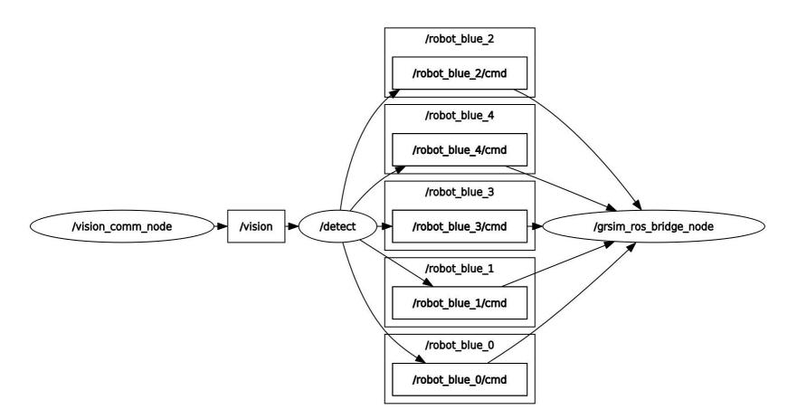
The software team initially attempted to develop the system entirely within Windows due to their familiarity with the environment. However, integrating core components with grSim[4] proved challenging without a native Bash shell environment. We explored Windows Subsystem for Linux (WSL), but its limitations for device connectivity (particularly with the camera and command sender board) made it unsuitable. To ensure functionality and streamline communication between high-level and low-level components (leveraging the grSim-ROS-bridge[6]), we opted for a dual-boot configuration with Ubuntu. This grants us the necessary flexibility in tool selection and removes the port-mapping limitations imposed by WSL's virtual machine environment.
Simulation
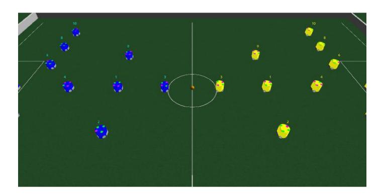
The simulation part is used to simulate how implemented instructions will drive the mechanics and check for errors in communication among strategy, skill layer, and nodes. The lack of a simulation system compatible with Google Protocol Buffers since last year has prevented us from creating simulations to test our strategies. Hence, this year we implemented a Simulation part to help us conveniently communicate with Google Protocol Buffers.
Skills
This layer oversees the transmission and execution of Python codes, and the connection between high-level and low-level. In essence, we developed Skill Node to serve as the intermediary, allowing every Skill to interact with nodes and packages, then send it to both grSim ROS bridge and low-level to be integrated. Last year, as we had a problem with communication/connection between low-level, in order to solve the problem, we created Node to be used for checking the connection between low-level and high-level to be more convenient to detect possible failure. Furthermore, more connections can be added in the future.
Utility
At the moment, the Utility layer contains the decision package, which is assigned to communicate with low-level components and determine the strategies to be executed. The underlying concepts of the decision package revolve around the scenario where the high-level system sends packages to the lowlevel system. It could encounter challenges in processing all the information simultaneously and end up checking only the most recent package. Consequently, we adopt the decision package to act as a buffer, delaying the transmission of information to the low-level system for it to appropriately handle and prevent possible errors.
Sequence
The Sequence layer is made up of a set of actions that configure the robot's movement. Skills utilization comes from the Skills layer, it enables the robot to execute different maneuvers, like moving back and forth and avoiding obstacles by moving to the predefined point, all in a sequential manner.
5 Conclusion
This TDP mentioned the changing of the robot in several aspects, from mechanical, electronic, low-level, and high-level respectively. All adjustments are based on experience and the blunders that the first generation faced. The mechanical part has changed the core structure to be able to accommodate more space for electronic design. The electronic design focuses on precision drive for the motor and kicker circuit. Low-level works on the newer and more stable communication system using JSON instead of pySerial used in the previous year. High-level is currently working on simulation using ROS-bridge with grSim to design strategy.
6 Acknowledgement
We would like to thoroughly express our dearest gratitude towards the financial sponsorship provided by the student affairs division of SIIT, as well as to gratefully acknowledge Assoc.Prof.Dr.Paiboon Sreearunothai for being our club advisor and Dr.Maroay Phlernjai for helping with technical support throughout the course of this robotic development.
References
- Blanchon, B.: Documentation arduinojson.org. https://arduinojson.org/v6/doc/ (2024)
- Maxonmotor: maxongroup.com. https://www.maxongroup.com/medias/sys master/-root/8816803348510/15-201-EN.pdf (2024)
- Maxonmotor: maxongroup.com. https://www.maxongroup.com/medias/ sysmaster/root/8882562924574/EN-21-295.pdf (2024)
- Monajjemi, V., Koochakzadeh, A., Ghidary, S.S.: grsim–robocup small size robot soccer simulator. In: RoboCup 2011: Robot Soccer World Cup XV 15. pp. 450–460. Springer (2012)
- Perez, B., Lam, D., Challa, S., Fu, K., Gynai, H., Sohrab, A., Clark, C., Srinivasan, A., Gordon, A.: Robojackets 2022 team description paper (2022)
- R.Grando, J.Dyonisio: GitHub-jardeldyonisio/grsim ros bridge: Simulação para competição UruCup. https://github.com/jardeldyonisio/grsim ros bridge (2022)
- Wasuntapichaikul, P., Srisabye, J., Onman, C., Damyot, S., Areeprasert, C., Sukvichai, K.: Skuba 2010 extended team description. Proceeding of Robocup (2010)