RoboCup 2024 TEAM DESCRIPTION PAPER Ri-one
Takumu Hirohashi, Yudai Matsumoto, Daiki Tomioka, Yuzuru Naito, Kaito Mitsuishi, Takae Obara, Ai Mitsushima, Ryosuke Murai, Sazuka Okunishi, Koutaro Ochiishi, Shutaro Otake, Bunichi Katsumi
College of Information Science and Engineering, Ritsumeikan University, Iwakura-cho, Ibaraki-shi, Osaka-fu, Japan
Abstract This paper describes the team's efforts to compete in the RoboCup 2024 soccer small league tournament. Based on the results of RoboCup2023, we also designed the robot and reconstructed the system. We are developed the hardware, circuits, and software.
On the hardware side, we introduced user interface (UI) features and describe our objectives and progress. We also propose a newly developed dribbler based on improvements to the existing machine. Finally, we experimented with the relationship of speed with kicker position.
In the circuit, we describe the improvements made to the kicker boost circuit and updated from last year.
Finally, in software, we propose an algorithm for a new soccer strategy and try to introduce new software to improve control and ball detection using cameras.
Introduction
We, Ri-one, are a student organization aiming to be the best RoboCup team in the world, recognized as a project team by the College of Information Science and Technology, Ritsumeikan University. Our team was formed 3 years ago and participated in the world competition for the first time at RoboCup 2022 Bangkok the year before last, where we placed 5th, and in Bordeaux last year, where we placed 3rd in the world. We are currently proceeding with development with the goal of winning the world championship. This TDP is a continuation of the team description paper for RoboCup 2023 and presents improvements and new developments compared to the previous version.
Hardware Development
This section covers the hardware improvements made for RoboCup 2024.
User Interface
This chapter describes the history and purpose of the UI implementation, the functions to be implemented, and the current development status.
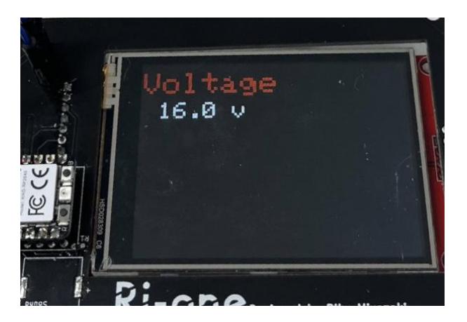
Purpose A display with a touch panel will be implemented on the top part of the robot. We plan to implement a function to measure and check the state of the robot and a test function to check if the kicker, dribbler wheel, etc. work. We believe that it is very effective to check the status and operation of individual robots. By checking for errors in assembly and functions of parts, the ideal performance can be achieved in a game. In addition, the robot can be handled more safely by implementing a function that capacitors discharge.
Features to be implemented
- Show battery voltage
- Kicker capacitor discharge function
- Test function to check whether the motor, dribbler, and kicker work
- Check if the acceleration/gyro sensor (IMU) works
Progress We implemented a function to display the remaining battery level. The main microcomputer that controls the robot reads the voltage, communicates it to the microcomputer that controls the display and shows on it.
Dribbler
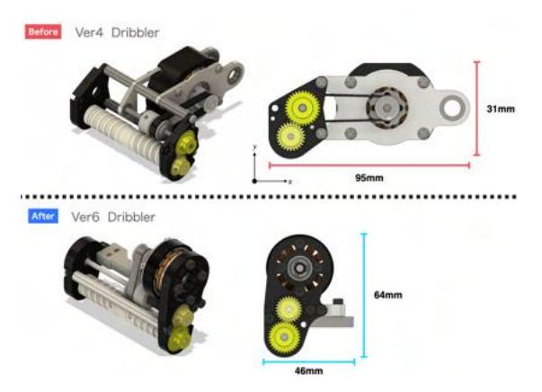
Problem with Ver.4 Dirbbler(2022) Our dribbler used an oil damper to absorb the shock of the catch. However, It had two problems. The first is that opportunities it works were limited. This is because it is difficult for robots to pass at high speeds of about 6.0 to 6.5 m/s, and our robot passes at about 3.0 to 4.5 m/s.
The second was that the dribbler itself was too large, so we developed a new dribbler to solve these problems.
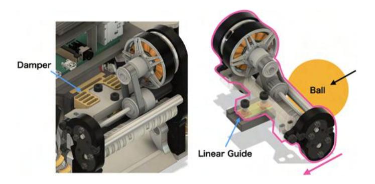
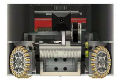
Ver.6 Dribbler(2024) The Ver. 6 Dribbler was developed with the goals of "downsizing" and "improving retention ability" when catching the ball. To achieve these goals, a linear guide was adopted instead of an oil damper.
This change has the advantage that the motion becomes a linear and the mechanism becomes simpler. This is useful for motion analysis and experimentation. In addition, a damper is installed in a position to absorb the shock by utilizing this linear motion. The shape of the damper can be easily changed, allowing the use of a honeycomb structure, which is ideal for shock absorption. The honeycomb structure has been recognized for its usefulness in many studies and is widely used. The advantage of this structure is that it can be applied and integrated into a robot.
As a result, the proposed mechanism has successfully reduced the size of the robot, especially in the x-axis direction. Furthermore, the ability to hold the ball during catching has been confirmed to be stable.
However, the effectiveness of this mechanism has not yet been academically proven. We plan to experiment and evaluate the usefulness of this mechanism.
Straight kick experiment
Introduction In this section, we will take up the kicker mechanism, which has the role of kicking the ball, and discuss appropriate position. In previous kickers, the force obtained by the coil could not be sufficiently reflected in the power of the kick. The reason for this is that the distance between the ball and the kicker's contact surface is so short that the ball cannot gain sufficient acceleration before it is kicked. This chapter presents the results of an examination of how far a kicker can kick a fast ball by changing the kicker's stroke distance and by changing the kicker's position.
Purpose of experiment Examine the relationship between the speed of the ball and the fixed position of the kicker mechanism.
Experimental Method
- The main board to operate the kicker and the kicker boost circuit are from the previous model. For the power supply, a stabilized power supply was used instead of a battery to match the voltage used in the experiment.
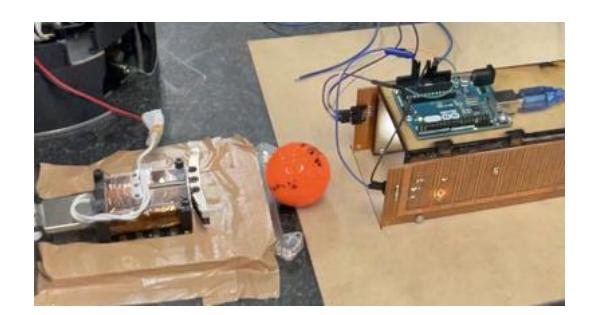
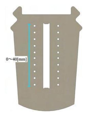
- Fix the kicker to the bottom board made for the experiment Fig.5A, and further fix it to the desk with tape. Kicker distance parameters can be changed.
- Determine the speed at the moment the kicker kicks the ball by using a homemade velocity meter. The velocity was obtained by measuring the time the ball passes between two points (100 mm).
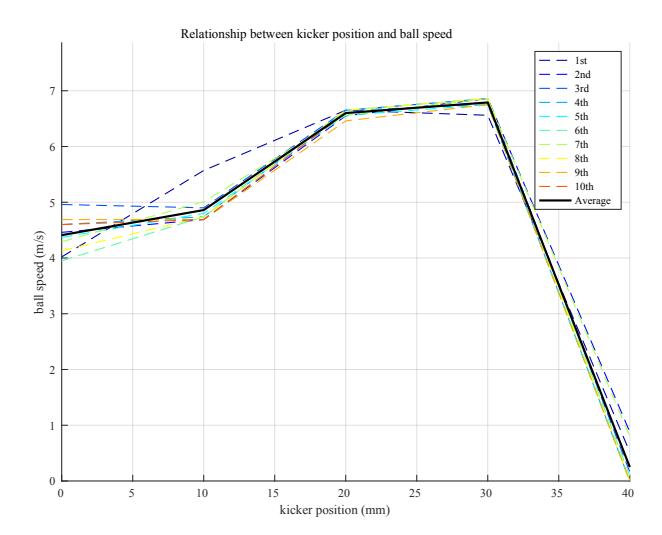
- The kicker is operated 10 times each from a point 10 mm, 20 mm, 30 mm, and 40 mm behind the contact surface of the ball and kicker, respectively.
- The average velocity was determined for each of the 10 kicker movements, and the values were compared to determine which position would allow the kicker to kick the hardest.
Result The results of the experiment are shown below. When the kicker was shifted backward by 20 or 30 mm, the ball was often kicked out at 6.5 m/s or more in most cases. In particular, when the kicker was shifted 30 mm backward, the kicker was able to kick the ball at 6.5 m/s or more in all trials.
When the kicker was displaced 40mm backward, the velocity was zero because the kicker never reached the ball.
Future Prospects In the experiment, we confirmed that by placing the kicker at an appropriate distance, the ball can be kicked with sufficient acceleration. The chip-kick experiment was also conducted in the same manner, but will be omitted here for reasons of documentation.
In the future, we would like to quantitatively evaluate the kicker based on its electrical and mechanical characteristics. Based on this, we would also like to conduct experiments to miniaturize the kicker.
Circuit Development
This section covers the improvements made to the circuit system for RoboCup 2024.
Boost circuit 2023
The boost circuit developed last year had issues with insufficient kick power and safety concerns. To resolve these issues, instead of using a chopper method, a transformer approach was adopted. We successfully raising the output voltage from $150\mathrm{V}$ to $250\mathrm{V}$. Additionally, by using an isolated half-bridge gate driver, it was possible to separate the high voltage and low voltage sides, enhancing safety.
Problem with Boost circuit 2023 However, last year's design had several problems. Although the kick power improved, the output voltage couldn't be adjusted, limiting it to kick only with a constant power. Moreover, the physical distance between the boost IC and the main board necessitated numerous pin connections, making the connection process challenging. Also, the boost IC sometimes broke during continuous use of the solenoid. Furthermore, the lack of a function to completely discharge the capacitors in the boost circuit was dangerous, as they remained charged after the robot was powered off.
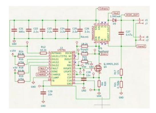
New Circuit Improvements 2024 In the new circuit, an electronic volume was first installed to adjust the kick power. Connecting an electronic volume to the boost IC made it possible to vary the output voltage from 150V to 200V, allowing for adjustment of kick power according to the situation.
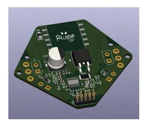
Moreover, a sub-microcontroller was installed independently of the main board to monitor the boost IC, resolving the connection issues. This sub-board has the following advantages:
- The sub-microcontroller specializes in controlling the boost circuit, improving the processing efficiency of the main board.
- As the main board and sub-board are independent, maintenance and debugging have become easier.
- The high voltage parts inside the boost board, especially the boost IC, are easily removable, allowing for quick replacement in case of failure.
Furthermore, the implementation of the sub-board made it possible to expand the boost circuit. A battery protection circuit was installed, and a thermistor was placed on the solenoid coil part, enabling temperature management of the solenoid. This system monitors the temperature of the solenoid coil to ensure it remains within a safe range and can automatically reduce power if a certain threshold is exceeded. This prevents overheating of the coil, thus avoiding damage.
Also, changing the boost IC from LT3750 to LT3751 improved the voltage adjustment function and supported a wider range of input voltages, among other additional features. This allows for more precise control.
Conclusion By identifying the problems with last year's boost circuit, a new boost circuit was designed based on these findings. This new circuit has many improvements, including adjustable output voltage, enhanced safety, ease of connection, and ease of maintenance and debugging. These improvements have made the boost circuit more reliable and efficient.
Software Development
This section covers the software improvements and new developments for RoboCup 2024.
Ball detection by camera
Challenges in Ball Recognition Ball recognition has been considered by so many teams in recent years, and Ri-one is no exception: not only can the robot track the ball using Vision, but it can also see the ball itself, enabling advanced ball capture. robot/ball image recognition developed by RoboCIn, connected an external device, Google Coral, to a Raspberry Pi to achieve high accuracy and real-time performance in image recognition using machine learning. However, these TPUs (Tensor Processing Units) are relatively expensive, yet installing them in all robots would be rather expensive.
There are also other methods of recognizing balls, such as color detection and contour detection.
Since color detection is only masked by color, it can operate at high speed without a TPU connected. Furthermore, as long as the color does not change, the ball can be recognized and tracked with high accuracy. However, when the color of the ball changes or the competition site changes, the accuracy becomes low due to color reflections and other factors. Therefore, it does not have excellent generalization performance. Another possible method is to use contour detection. This method extracts and detects the circular areas of the ball, and is somewhat more accurate. However, it takes a very long time to detect the contour and is not excellent in real-time. Another problem is that if another circular object is present, it is mis-detected as a ball.
Proposed Ball Recognition System We have developed a ball recognition system that detects balls with high accuracy using a simple process while also providing excellent generalization performance. Unlike previous systems that used a single method to detect balls, we utilized two methods: machine learning ball detection using YOLOv8 and ball detection using color detection.
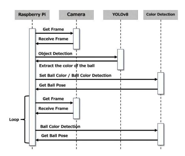
Algorithms The following procedure is used to detect and track the ball.
The coordinates of the ball are extracted by YOLOv8 at program startup, i.e., when the robot starts up. This enables detection regardless of the physical environment in which the robot is moved (e.g., on the field, under light, etc.). After that, color detection and coordinate extraction are performed at high speed to achieve fast ball detection.
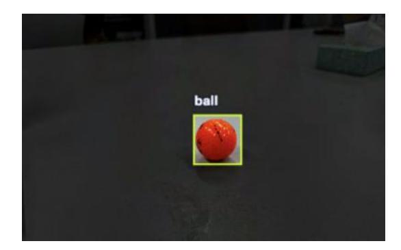
Creating a training dataset for YOLOv8 In order to detect balls with YOLOv8, it is necessary to train the ball data. The annotation process in creating the dataset was as shown in the figure, and 93 images were prepared. After augmentation, we had 223 images, 195 for training, 18 for validation, and 10 for testing.
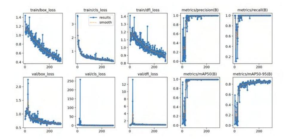
Based on the created dataset, we performed the training. The results are shown in the table below.
The recognition accuracy for the test data was 99.7%, which is very high. However, the graph shows that 100% has already been reached in the early learning stage. This is thought to be due to overlearning caused by the small amount of test data. In order to further improve the generalization performance, it is necessary to take more images.
The recognition was performed using the created model. 2FPS was used for recognition on the Raspberry Pi. This is fatal for applications that require realtime performance. To solve this problem, a color detection algorithm was used.
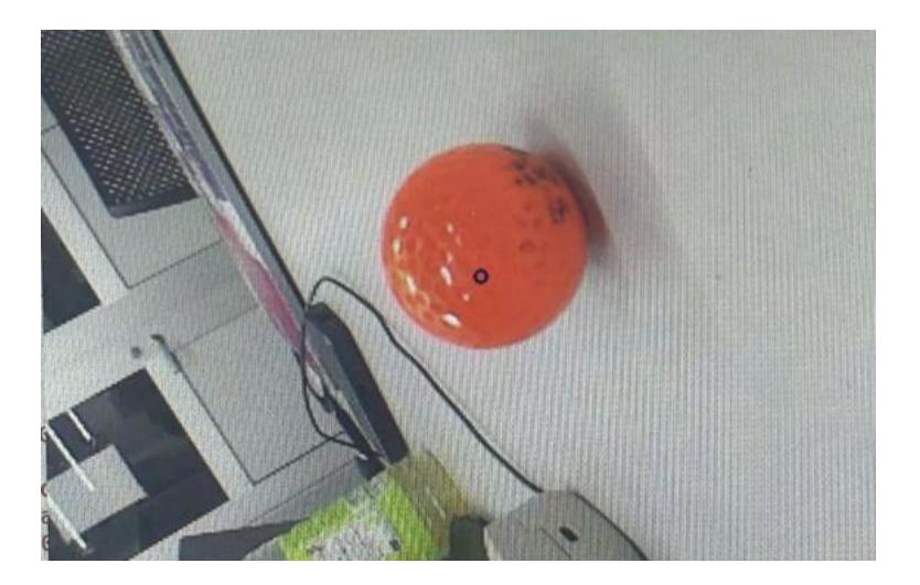
Color Detection Algorithm The color of the center coordinates of the ball information recognized by YOLOv8 and four nearby points are extracted and averaged to detect the ball. Here, the reason why four points are used for detection is because the center of the ball may be filled in with text. This avoids black color in the extraction if a logo or other symbol is drawn in the center.
Specifically, a mask is applied with the extracted color, and the center-of-gravity calculation is applied to the extracted area. This process allows us to recognize the coordinates of the ball.
As long as the exact same color did not exist in the surrounding area, the ball could be recognized with high accuracy. As shown in the figure, the coordinates are circled in blue.
The average FPS was 44FPS. The maximum value was 120 FPS, which is considered sufficient for real-time use.
System Evaluation By using YOLOv8 and color recognition, we have achieved a fast ball coordinate recognition system that can adapt to various environments. In the future, we would like to mount this system on all robots and implement programs such as tracking.
Comparison of ball detection methods
| YOLOv8 | Color Detection (OpenCV) | Contour Detection (OpenCV) | |
|---|---|---|---|
| Processing Speed | Slow | Fast | Very Slow |
| FPS | 5 FPS | 30∼120FPS | 1FPS |
| Precision | Higher | Higher | Higher |
| Generalization Performance | High | Low | High |
Learning Results
| mAP | Precision | Recall | |
|---|---|---|---|
| 99.5% | 99.7% | 100.0% |
Control
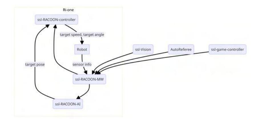
We have been using ssl-RACOON-AI software to define both the strategy and some of the control of the robot. So we made the control part in ssl-RACOON-AI independent from AI as ssl-RACOON-controller.
In this configuration, the AI determines the strategy based on information received from the middleware and passes the robot's skills and target coordinates to the controller. The controller determines the target speed of each robot based on the information received and sends it to the robots. With this change, the controller aims to reduce the number of fouls such as crashes and encroachments into prohibited areas by using the controller to generate trajectories. In addition, improved speed control is expected.
Strategy
Our team decided to improve the behavior of the robot in all position based on the results of previous Robocup.
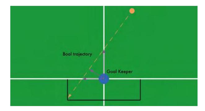
Goal Keeper Conventional goalkeepers only placed the goalkeeper in the same y-coordinate component as the coordinates of the ball. This did not make the goalkeeper a great defender. Especially if the enemy is a team that plays a shoot after pass strategy, the goalkeeper will be shaken up and allowed to score. In addition to this, the total distance traveled is also greater, which poses a significant risk to the goalkeeper's battery.
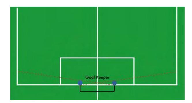
There, we examined the goalkeeper's movement and goal defense rate against enemy shots. The first strategy is to move the shortest distance between the predicted trajectory of the ball and the current location of the goalkeeper to protect the shot. This method was not employed because it has the disadvantage that goalkeeper is somewhat difficult to control because it requires movement of both the x and y components, and also because the goal defense rate is low. The second strategy is to prevent the ball at the intersection of the predicted ball trajectory and the GOAL LINE. This method was able to limit the movement component of the goalkeeper to the y-axis direction only, and also had a high goal defense rate. The third strategy is to prevent the ball at the intersection of the predicted trajectory of the ball and the line y=0 (the bisector of the goal). Although this method can limit the movement component of goalkeeper to the x-axis direction only, we chose not to employ this method as well in order to use it in conjunction with the strategy described below. Against shots from the front or diagonally, we decided to defend by moving only horizontally (the second strategy).
In addition, shots such as those from right next to the goal, were almost always successfully prevented by positioning right next to the goal post.
Additionally, the goalkeeper's reaction time and movement speed can be improved by predicting the shooting course even before the enemy shoots, based on all kinds of information about the ball and enemy robots, and by setting the goalkeeper's destination farther away than the intersection of the actual shooting course, The goalkeeper's ability to defend the goal by itself was also improved.
Defense Conventional defenses consist of three or four robots surrounding a DEFENSE AREA, with all defensive robots positioned in locations dependent on the location of the ball. With this arrangement, the defensive robot cannot handle large ball displacements, such as passes. Therefore, as a new defensive robot arrangement, we distributed each defensive robot by weighting not only the ball but also the enemy robots, and succeeded in preventing shots derived from passes outside the defensive area.
Ball Placement In the conventional ball placement algorithm, the ball placement was performed by dribbling backward no matter where the ball was located. By limiting backward placement to only when the ball is near the wall, the time required for ball placement was shortened and the success rate within the time limit was increased. In addition, the robot's movements and speed could be finely tuned to achieve more accurate ball placement.
Offense The conventional offense aimed only at the center of the goal when shooting, but an algorithm was added that looks at the enemy goalkeeper and defensive positioning and selects the best shooting course. Furthermore, in addition to the above, by deriving the shot from the pass, the player succeeded in leaving many options for the shooting course, thus improving the scoring rate.
Conclusion
In this paper, we have discussed and introduced our new improvements. As we discussed in this paper, our team have been focus on developing our software system and machine hardware itself, and our improve should lead us to win the championship. Still some of them are under development, however, we will continue developing to make success in the competition.
References
- Ogasawara Nagahisa, Masaki Shiratori, "Study on Impact Absorption of Honeycomb Structural Materials", Transactions of the Japan Society of Mechanical Engineers, vol.63 No,09-0427,1997
- Cecília Silva, Charles Alves, Edgleyson Silva, RoboCIn Extended Team Description Paper for RoboCup 2022