RoboCIn Small Size League Extended Team Description Paper for RoboCup 2024
Alberto Franca, Beatriz Barros, Cauê Gomes, Cecília Silva, Charles M. Alves, Davi C. Barbosa, Driele Xavier, Elisson Araújo, Felipe Pereira, Hierlan A. Batista, Lucas H. Cavalcanti, Marcela Asfora, Matheus Alves, Matheus Paixão, Matheus Vasconcelos, Matheus Vinícius, João G. Melo, José R. Silva, José V. Cruz, Júlia Leite, Pedro H. Santana, Pedro P. Oliveira, Riei Rodrigues, Ryan Morais, Tamara Teobaldo, Vinícius Dutra, Victor Araújo, Edna Barros
Centro de Informática, Universidade Federal de Pernambuco. Av. Prof. Moraes Rego, 1235 - Cidade Universitária, Recife - Pernambuco, Brazil.
Abstract RoboCIn has participated in RoboCup Small Size League since 2019, won its first world title in 2022 and second in 2023 (Division B), and is currently a four-time Latin-American champion. This paper presents our improvements to find a great first campaign at Division A in RoboCup 2024 in Eindhoven, Netherlands. During 2023, our team has successfully published 3 articles related to SSL at two high-impact conferences: the 26th RoboCup International Symposium and the 20th IEEE Latin American Robotics Symposium (LARS 2023). Over the past year, we have sought to improve our system and robots structurally, simplifying processes, improving performance, and providing more reliability. Furthermore, we'll discuss the software improvements to increase the number of players as required in Division A.
Keywords: RoboCIn · RoboCup 2024 · Robotics · Small Size League
1 Hardware
RoboCIn's brief competition history has focused on refining methods to optimize and enhance the robot's systemic functionality. Alongside this progress, we have learned from various mistakes, yielding valuable insights that have significantly contributed to our ongoing development. This section centers on the v2024 generation, spotlighting its features and explaining the measures implemented for enhancement. Notably, the team endeavors have led to modifications in the drive set, aiming to guarantee robust and consistent performance in competitive environments.
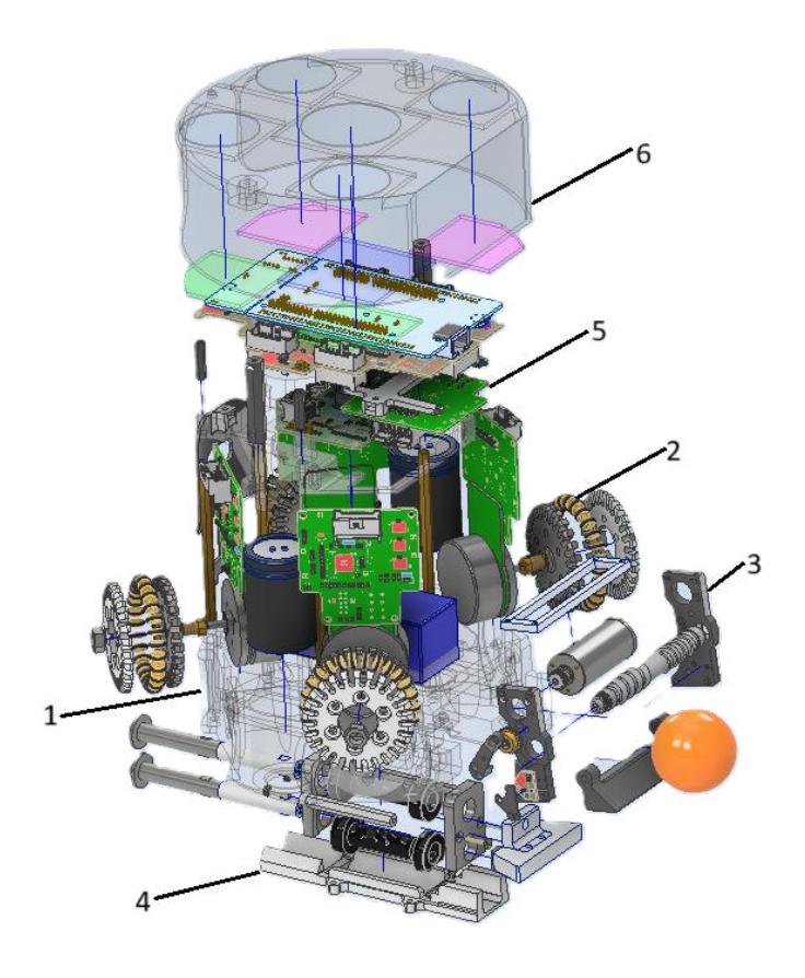
In figure 1, the following main parts of the robot can be visualised:
1 - The base frame serves as the core structure of the robot, where all components (excluding the cover) are directly mounted. It is crucial to note that the base itself requires careful consideration prior to undergoing the 3D printing process. High density should be incorporated into the fastening areas for the powertrain parts and fixation.
- 2 A direct drive set with wheels and motor board is employed, featuring a specific motor axis configuration. The front angle aligns with the robot's X-axis (parallel to the front), and the wheel shaft is set at 30°, while the rear angle is configured at 45°.
- 3 The dribbler mechanism comprises the dribbling motor, dribbling bar, a gear connection linking them, and electronics for the front brake beam to detect the ball.
- 4 The kicker assembly consists of two cylindrical plungers one for front kicks and one for chip kicks – along with two coils and two capacitors.
- 5 The second floor encompasses a battery, a power board for kick discharge, a mainboard for control, and the dribbler board.
- 6 The 3D printed cover completes the assembly.
1.1 3D Printed parts
Over the past few years, the RoboCIn team has used 3D printing as the primary tool for manufacturing SSL robot parts. This is due to several factors, including ease of use, lower production costs, and the absence of members with expertise in areas such as machining.
The critical factors that damages 3D printing process is the high maintenance costs of parts, printing failures leading to lost printer hours, lower durability, deformation occurring when motors heat up (causing PLA wheels, which starts deforming at 60°C, to alter the motor's rotation axis, pressing against the base and jamming, potentially damaging the motors), and reliance on 3D printers; considering the printing time, which can exceed 20 hours, and the high demand for parts, meticulous planning was necessary to ensure everything was ready on time.
However, the increased durability of machined parts allows them to be used for years without needing replacement, with much lower long-term maintenance costs and providing greater security during competitions by avoiding deformations, this is due to the higher melting temperature of aluminum compared to PLA, this change also reduces dependence on 3D printers.
With the possibility of using machined parts, we made improvements to the drive set, mainly in the wheels, which relied a better stress resistance than the printed parts could provide.
1.2 Direct Drive
The v2022 wheels were 3D printed with PLA material and had a diameter of 45mm. Due to the embedded gearing system (3.3:1), the motor system could provide more torque to the robot. However, there were significant losses in movement due to backlash from the gears' tangency [3], and the system couldn't ensure parallelism of the motor and wheel centerlines. To achieve a smoother solution, the way the wheels were attached was modified.
Most of the time, an SSL robot is accelerating, rarely moving at a constant speed. Therefore, optimizing the motor's operating point for acceleration makes sense, and becomes crucial for the motor's lifespan and maintaining a good energy balance. This is achieved when the motor system is designed to operate at maximum efficiency, given that at a constant applied voltage and due to the proportionality of torque and current, efficiency increases with increasing speed (decreasing torque). However, at low torques, the significance of friction losses becomes more pronounced, causing efficiency to rapidly approach zero.
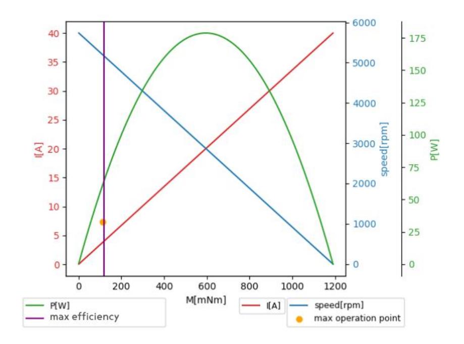
The 50W Maxon motors through direct drive work at a maximum operating point around 10 percent of the stall torque, near maximum efficiency [7]. For this change to be possible, the wheel size increased compared to v2022, with a total diameter of 62mm. The ideal wheel size for an SSL robot is always a compromise between various factors, such as the robot's maximum speed, transmission ratio, and the efficiency. These factors culminate in the motor characteristic curve(Figure 2) [6].
As a result, it becomes possible to reduce the overall complexity of the power transmission, the v2024 robots now use this approach, meaning no gears are involved. The main disadvantage of this change is the increase in energy consumption. However, this increase was deemed acceptable due to the high losses from the gearing. The benefits include more responsive control and allowing higher maximum speeds due to the accentuation of power in the characteristic curve.
2 Control
At the RoboCup 2023, we experienced some issues regarding the robot's motion control, primarily due to our transition from a geared system to a direct transmission, which reduced the encoder's counts per turn (CPT) available for measuring the wheel speed and changed the motor's operating range, causing a significant impact in the motors' behaviors during the robot's motion. These problems were related to the control stabilization time at the desired speed for the motor, generating errors in the final desired speed for each axis of the robot.
Our onboard control is implemented with individual PI controllers for each wheel; therefore, the PI gains must be readjusted to the new system accordingly. However, this procedure could not be done in time for RoboCup 2023, which led to difficulties tuning the robot's motion control. To solve that, we implemented a robot-level velocity control on top of our existent controllers, i.e., a PID controller for each translation and rotation axis. This solution enabled our robots to move more accurately during matches, although it caused our motors to heat up, even leading to deformations in our 3D-printed base. Consequently, it caused permanent damage to some of our motors during the competition.
To address this problem adequately, we reproduced the experiments employed in the previous robot version for tuning the motors' PID controller, which uses the Multi-level PseudoRandom Sequence (MPRS) technique of control inputs for system identification [1]. This Section describes the approach we utilized and the experiments realized to identify the motor, tune the PID controller gains, and validate it with the robot motion.
2.1 System Identification and PID Tuning
The approach utilizes a transfer function to approximate motor behavior, implemented through MATLAB's System Identification Toolbox [4]. This toolbox facilitates the identification of a function that describes the specific motor behavior. To identify the transfer function, we need to extract samples from an actual motor that the toolbox can use.
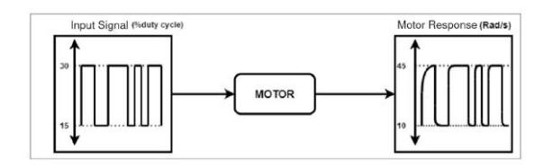
The strategy for data collection uses MPRS to generate control inputs for the motors. This strategy consists of generating several values within the motor working range and applying them in a real scenario to capture all the external factors that influence the application [1]. The number of elements of the sequence should be large enough to get a good fit for the system identification. The number of samples is determined by the confidence interval we want to achieve during the system identification. Although it has recommended a sequence of around 400 samples, experiments with 30 to 50 samples showed similar results.
Briefly illustrated in Figure 3 is the data acquisition process for building the motor model. In this case, we send an input signal in MPRS format to the motor with parameters relevant to its application. The encoder then captures the motor response at a specific sampling rate, translating it into rotational speed in rad/s.
2.2 Validation
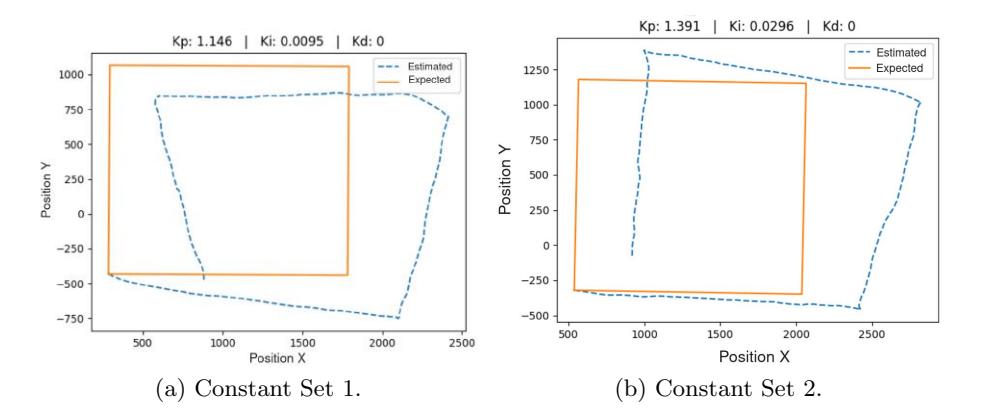
This section describes the experiment used to validate the implementation of the PI controller. Analyzing whether the control constants obtained during tuning yield results consistent with the specified parameters is essential. The experiments were conducted in a real-world validation environment.
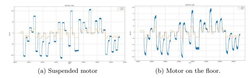
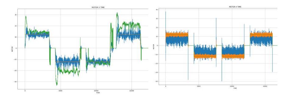
Motor response behavior The initial experiment involves analyzing the motor response at various reference speeds. Twenty arbitrary values will be selected and transmitted to each motor with a pre-defined time interval between each reference speed. Figure 5 illustrates the experiment applied to one of the motors using the control constants found in the tuning stage, demonstrating an interval of 3s between each speed. This phase aims to examine the motor's behavior during speed transitions and verify its ability to stabilize the desired speed. The data collected shows that the error associated with controlling the motor speed decreases significantly, generating more stability in the control of the robot. This observation of the data allows us to assume that the motor's response to speed changes was satisfactory.
3 Software
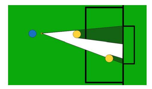
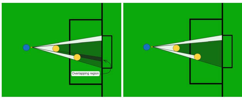
This year, our team concentrated on improving crucial elements of our in-game decision-making. A primary focus was refining the decision between passing and kicking, which was achieved by implementing a new heuristic based on the raycast algorithm. We also developed a dynamic positioning system for our robots, incorporating the algorithm and additional heuristics for a more robust approach.
The previous heuristic considered both kick-on-goal and pass probabilities as one, then decreased each probability based on factors like the presence of an enemy between the forward and the goal, reducing the kick probability. The need for a new heuristic comes from the old one lacking robustness, relying on arbitrary "magical numbers" that led to inconsistent decisions and suboptimal choices, such as passing when kicking was more viable. Moreover, the complexity of the old heuristic made it challenging to comprehend and modify efficiently, resulting in a time-consuming process for any necessary adjustments. The new heuristic aims to be more robust, providing more logical and understandable decision-making for the software.
The positioning system is another point that was addressed in 2023. Previously, the positions of our attacking robots were determined by a fixed correspondence between the ball's position and specific positions on the field. This static approach led to difficulties in evading enemy marking, especially in direct kick situations, making several plays impossible and reducing shooting opportunities on goal. In 2023, we developed a new positioning system that uses the new heuristic mentioned above to dynamically distribute our players on the field, actively trying to eliminate enemy marking, shifting from a fixed to a dynamic positioning system.
3.1 Shadow Heuristics
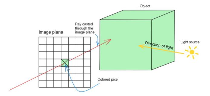
The recently developed and implemented heuristic is based on the Raycast algorithm. The Raycast is an algorithm used in computer graphics to calculate the illumination of a scene or an environment. In its 3D version, as seen in Figure
3.2 Support Positioning
Over the years, the team's positioning system has stayed relatively untouched while we developed other software parts. It was based on fixed positions on the field according to the ball's position, but it did not react to enemy marking, meaning that the robot handling the ball had no good passing option if all supports were marked, blocking our playstyle.
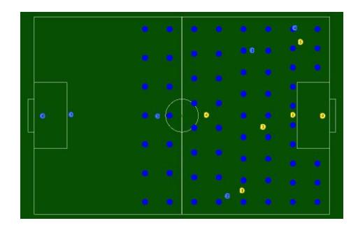
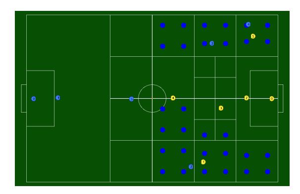
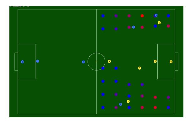
To address this issue, we developed a dynamic positioning system capable of reacting to enemy defense marking, adjusting to eliminate it, and creating new situations that keep the opposing defense in a reactive state, always behind our team's movements. The positions assigned to supports cannot be fixed for dynamism and should vary over time. Our chosen approach involves sampling points on the field at specific time steps and evaluating them using indicators, similar to what SRC described in [9]. As our goal is to choose optimal points to receive the ball, these indicators are the factors for the final probability of a pass.
Pipeline for dynamic positioning The decision module handles point selection calculations to coordinate multiple players [8]. To organize the implementation, we have divided it into a series of steps, forming the pipeline illustrated in Figure 10.

4 Migration to division A
Given the success and performance in the last campaigns in Division B, RoboCIn is structuring itself to participate in Division A in 2024. We see this as a new level of challenge and possibilities for the project; playing in Division A means evolving and maturing the project at several points. To keep more robots up and running efficiently and without the overhead of the mechanical team for maintenance between games, we are looking to improve reliability and optimize the robot, as explained in Section 1. Furthermore, as we will have more robots, we seek to expand our decision heuristics and the level of multi-agent cooperation, such as structuring complex plays that involve more than two players together, based on the plays described in the STP [2].
4.1 Ball Placement Strategy
Ball placement is a requirement to be able to participate in Division A and Division B. It appears to be a technical challenge; given the performance obtained in this challenge during RoboCup 2023, RoboCIn decided to extend its use to games, an effective strategy that extensively validated our ball placement behavior.
In our high-level software, when the ball placement command is received from the referee, the team divides into two groups, one to execute the action and the other to avoid the exclusion zone.
The following behaviors or a combination of them will be performed, depending on the context, to get the ball to the defined location:
- If the ball is out of bounds or close to a wall: As our robot's dribbler mechanism is still in development and currently not used by the software stack, we kick the ball diagonally against the wall so that it returns to the pitch and preferably closer to the target position.
- If the ball is far from the target: We use two robots to quickly take the ball to the goal with one pass, where, ideally, the second robot already receives the ball at the expected destination.
- If the ball is close to the destination: The robot will push the ball to the determined destination, stopping a little before estimating how far it will roll after the robot stops.
While the ball placement occurs, the other robots must avoid interfering with the process by avoiding the exclusion zone created, but simply collecting the team to a position as far away as possible is ineffective.
In our approach, we place the other robots in a line along the x-axis of the field, with a displacement in the y-axis to be on the opposite side of the ball's position. As the ball placement progresses, the teams gradually move from the position they assumed in the referee's stop command to the ball's destination position.
With this, the team will be positioned to quickly return to the game without invading the ball placement exclusion zone, especially without being unprotected from a quick return from the other team.
5 Acknowledgement
First, we would like to thank our advisors and the Centro de Informática (CIn)- UFPE for all the support and knowledge during these years of project and development. We also would like to thank all our sponsors: Moura Batteries, ITEMM Institute, Microsoft, CESAR, Neurotech, Incognia, HSBS, Embraer, Instituto Nacional de Engenharia de Software (INES), Maxon Motors, and Mathworks.
References
- Araújo, V., Martins, F., Fernandes, R., Barros, E.: A telemetry-based pi tuning strategy for low-level control of an omnidirectional mobile robot. In: Alami, R., Biswas, J., Cakmak, M., Obst, O. (eds.) RoboCup 2021: Robot World Cup XXIV. pp. 189–201. Springer International Publishing, Cham (2022)
- Browning, B., Bruce, J., Bowling, M., Veloso, M.: Stp: Skills, tactics, and plays for multi-robot control in adversarial environments. Proceedings of the Institution of Mechanical Engineers, Part I: Journal of Systems and Control Engineering 219(1), 33–52 (2005)
- Bruns, R., Diepstraten, J., Schuurbiers, X., Wouters, J.: Motion control of systems with backlash (2006)
- Games, R.B.: 2d visibility, https://www.redblobgames.com/articles/visibility/
- Geiger, M., Carstensen, C., Ryll, A., Ommer, N., Engelhardt, D., Bayer, F.: Tigers mannheim (team interacting and game evolving robots) extended team description for robocup 2017 (2017), robocup Small Size League, Mannheim, Germany, 2017
- Geist, H.F.: Torque characteristics of various types of electric motors. pp. 6–16 (1912)
- Maxon-Group: maxon dc motor and maxon ec motor key information, https://www.maxongroup.com/medias/sys_master/8815460712478.pdf?attachment=true
- Oliveira, A., Gomes, C., Silva, C., Alves, C., Souza, D., Xavier, D., Silva, E., Martins, F., Cavalcanti, L., Maciel, L., Paixão, M., Vasconcelos, M., Vinícius, M., Melo, J.G., Moura, J.P., Silva, J.R., Cruz, J.V., Santana, P.H., Oliveira, P.P., Rodrigues, R., Fernandes, R., Morais, R., Teobaldo, T., Silva, W., Barros, E.: Robocin extended team description paper for robocup 2023 (2023), robocup Small Size League, Recife, Brazil, 2023
- Tan, Y., Jiang, L., Peng, J., Chen, Z., Li, Z., Bao, Y., Zou, Y., Shi, R.: Src extended team description paper for robocup 2023 (2023), robocup Small Size League, Shanghai, P.R.China, 2023