RoboFEI 2024 Team Description Paper
Alexandre A. Leme, Alvaro D. Neto, Danilo Y. Simomura, Eduardo R. Goncalves, Felipe Estevao C. de Mello, Giovanna Cecilia S. Quaresma, Guilherme Luis Pauli, Henrique B. Simoes, Joao Victor L. Aguiar, Leonardo da S. Costa, Matheus E. de S. N. Chiari, Rafael M. Cukier, Vincenzo S. Vasconcellos, Nityananda V. Saraswati, Prof. Flavio Tonidandel, Prof. Reinaldo A. C Bianchi, Prof. Plinio T. Aquino Jr
Robotics and Artificial Intelligence Laboratory Centro Universitario da FEI, Sao Bernardo do Campo, Brazil
https://gitlab.com/robofei/ssl · https://gitlab.com/leo_costa/RobotNavigation
Abstract This paper presents the current state of the RoboFEI Small Size League team as it stands for RoboCup International Small Size League competition 2024, in Eindhoven, Netherlands. The paper contains descriptions of mechanical design, studies made about chip kick efficiency, path tracking, obstacle avoidance and path planning.
1 Introduction
During 2023, for the mechanics, our team studied different parameters to improve the distance of the robot's chip kick, analyzing geometry and electric parameters.
Besides that, from last year, we can say that the electronic design built was a success and achieved good results in the competitions. Before it, RoboFEI had big problems because of the poorly constructed past design that barely handled a game without burning out after being unused during 2020 and 2021.
Regarding the software, RoboFEI made different studies about path tracking, path planning, and obstacle avoidance. The first was a study comparing the Linear Quadratic Regulator with the PID controller to evaluate which is better for tracking a path in the Small Size League. Regarding the other two items, RoboFEI made a deep study to analyze different obstacle avoidance and path planning algorithms while considering dynamic obstacles.
2 Mechanics
2.1 Introducing Robot Generation v2024
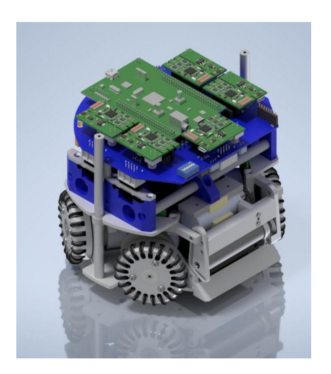
For RoboCup 2024, Team RoboFEI will adopt an old generation of mechanical parts due to the struggles of adaptation to the v2023, [1], although some improvements in the v2023 were added to the old model v2012 [2], creating the v2024, such as the wheels and the capacitors configurations from the v2023 and the dribbler and kicks of the v2012, as it's possible to see in Fig. 1.
This change was necessary, because of machining problems in the v2023 and the need for the same adjustment to this project to add more reliability, to the process of manufacturing and in-game. We are looking forward to having the opportunity to rebuild the v2023 for later this year and after major upgrades introduce the v2025 in RoboCup 2025.
2.2 Chip Kick
The Small Size League (SSL) is known for an extremely fast-paced soccer game with small robots, in those games the ball reaches a maximum velocity of 6.5 m/s, and robots, up to more than 2.5 m/s. To keep these velocities up, teams optimize their robots with powerful motors, solenoids, and a range of different electronic components and mechanical parts, always focusing on maintaining a balance between weight, precision, and disposition.
Besides the fast movement with the omnidirectional wheels, robots can make their shots with two different types of kicks, the direct kick, a straightforward activation, and the chip kick. This activation makes the ball move not only in horizontal lines but also vertically, making it overhead other robots. These two types of shots are made with a powerful charged solenoid that sends a pulse in one direction, this pulse moves a plunger attached to a mechanical part that enters in contact with the ball, producing different types of effect according to its format, height, and weight.
The purpose of the study was to reach the longest horizontal (x) distance, optimizing the chip kick of an SSL robot by changing its parameters. To understand and analyse the effects of varying the chip kicker and solenoid characteristics, a MATLAB® code was written out of the equations shown further below, they helped understand which parameters should be taken into account for the chip kick optimization.
After the coil parameters were calculated, the force that the solenoid generates in the plunger, the acceleration generated in the plunger, and its final velocity were calculated.
The force (F) was calculated considering the current passing through the solenoid, the number of turns, the permeability of free space, the cross-sectional area, and the distance from the plunger (Equation 1).
$$F = \frac{(I_f^2)(N^2)\mu_0 A}{2d^2}$$
To calculate the exact moment the ball stops receiving acceleration from the chip kicker movement and starts being affected by gravity acceleration a vector calculus with linear algebra was made, utilizing u and v as vectors and Rchip as the radius of the rotation axle (Fig. 2).
Using a dot product, it was possible to make an approximation (Equation 2):
$$\theta_{ball}(t=0) = \cos^{-1}\left(\frac{2R_{chip}^{2} - r_{ball}^{2}}{2R_{chip}^{2}}\right)$$
$$x_{b}(t=0) = R_{chip}\sin(\theta_{ball}(t=0) + \alpha_{chip})$$
$$y_{b}(t=0) = h_{chip} - R_{chip}\cos(\theta_{ball}(t=0) + \alpha_{chip})$$
$$x_{b}(t) = x_{b}(t-1) + v_{b_{x}} \times dt$$
$$y_{b}(t) = y_{b}(t-1) + v_{b_{y}} \times dt$$
$$\vec{v} = (x_{b}; y_{b} - h_{chip})$$
$$\vec{u} = (x_{c}; y_{c} - h_{chip})$$
$$\theta_{ball}(t) = \cos^{-1}\left(\frac{u_{x}v_{x} + u_{y}v_{y}}{|\vec{u}| |\vec{v}|}\right)$$
With the implementation of the code, it was possible to scale what the changes that occur in the solenoid and in the plunger generate in the distance the ball travels, which demonstrates which parameters are best to modify to change how far the ball travels or the maximum height it will reach.
To perform the tests, some parameters were chosen to verify which makes it easier to adjust the maximum distance the ball reaches. These included the distance traveled by the coil, the current in the coil, the number of coils, the length of the base of the rectangle trapezoid, and the radius of the chip kick.
The first test (Fig. 3) consists of modifying the distance traveled by the plunger. It was possible to verify that, the farther away from the solenoid, the lower the force generated by the plunger in the golf ball, this happens because, in places further away from the solenoid, there is less interaction with the magnetic field.
The second test (Fig. 4) changes the current applied to the coil. In this test, it was found that, as the current increases, the greater the distance traveled by the golf ball will be, that happens due to the variation of the current, generating the variation of the magnetic field intensity.
The third test (Fig. 5) is the variation in the number of coil windings. This test demonstrates that as the number of windings in the coil increases, there will be an improvement in the distance traveled by the golf ball, this phenomenon is the result of the variation that happens in the magnetic flux affected by increasing the number of spiral coils.
Changes in the height of the chip kicker axle of rotation influenced the axis of rotation angles, or as previously shown in Fig. 2 (Rchip). Fig. 6 shows results for maximum distance traveled when adapting (Rchip).
When analyzing the results of the test, it can be seen that the easiest method of modifying the force the coil generates on the clutch is to modify the distance the plunger travels. However, if there is no space for this type of modification one option is to change the number of coils or change the current applied, in the latter case it must be checked that the copper wire used to assemble this coil has a resistance that will resist the new current.
The in-depth study with the full results was published in the 2023 Latin American Robotics Symposium (LARS) [3], and the MATLAB® is available in RoboFEI's GitLab [4].
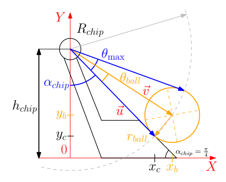
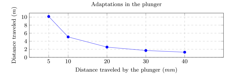
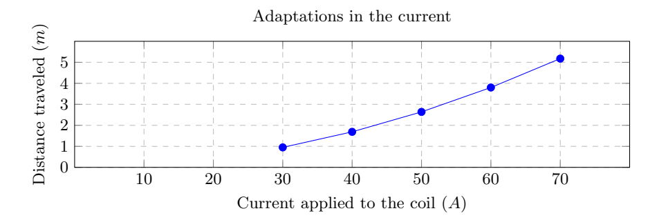
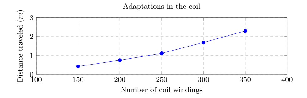
Table 1. Robot Specifications
| Robot version | v2023 | v2024 |
|---|---|---|
| Dimension | Ø179 x 150mm | Ø179 x 150mm |
| Total weight | 2.5 kg | 3.0 kg |
| Driving motors | Maxon EC-flat-45 50W 18V | Maxon EC-flat-45 50W 18V |
| Gear | 3:1 | 3:1 |
| Gear type | Internal Spum | Internal Spum |
| Wheel diameter | 54mm | 54mm |
| Encoder | US DIGITAL E4T-1000-157-S-H-M-B | US DIGITAL E4T-1000-157-S-H-M-B |
| Dribbling motor | Maxon EC-max-22 25W 18V | Maxon EC-max-22 25W 18V |
| Dribbling gear | 7:3 | 7:3 |
| ø Dribbling bar | 9.5 mm | 16 mm |
| Kicker charge | 2x 1000µF @ 200V | 2x 1000µF @ 200V |
| Straight kick speed | higher than 6.5 m/s | higher than 6.5 m/s |
| Microcontroller | STM 32F4011 | STM 32F4011 |
| Sensors | Encoders, Gyroscope, Accelerometer | Encoders, Gyroscope, Accelerometer |
| Communication link | nRF24L01 transceiver, 2 Mbps, 2.4/2.5 GHz | nRF24L01 transceiver, 2 Mbps, 2.4/2.5 GHz |
| Power Supply | Li-Po Battery, 11.1 V nominal, 2200mAh | Li-Po Battery, 11.1 V nominal, 2200mAh |
3 Software
3.1 Navigation Overview
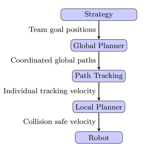
Since the last RoboCup, we have made major improvements in our navigation system. First, we separated navigation into two tasks: global and local planning. The former deals with coordination of robots' paths and static obstacles, and the latter deals with dynamic obstacles, i.e., collision avoidance and kinematic constraints. Fig. 7 represents the current navigation architecture used.
The strategy software calculates the goal position for each robot depending on the team's objective. This information is passed onto the global planner, which will find a set of suitable paths the robots must follow to reach their individual objectives, this is supposed to be the most expensive step of the navigation system and is supposed to run only if the robots' objectives change significantly. Then, the path tracking is responsible for generating the velocity for each robot in order to precisely follow each path, this is usually achieved through a Proportional-Integral-Derivative (PID) controller [5], or Linear Quadratic Regulator (LQR) [6] (also in Section 4). Finally, the local planner slightly modifies the robot velocity command in order to avoid collisions with dynamic obstacles. It can also optimize the velocity command with respect to kinematic constraints.
Since 2019, the Dynamic Visibility Graph A Star (DVG+A*) [7] has been used as a path planning algorithm (global planning). It is an improvement over the classic A* algorithm with a lower computational complexity. Basically, the algorithm creates a dynamic visibility graph, which is used to find the robot's path using an A* search. More details can be seen on [7,8]. The DVG+A* is an effective algorithm that can reasonably handle the requirements for the SSL robots, provided that it is paired with an appropriate local planner to adapt the trajectory as needed.
3.2 Safety Based Local Planner for Obstacle Avoidance
The Probabilistic Safety Barrier Certificates (PrSBC) [9] is the chosen local planner. It is a control barrier function-inspired controller that models the uncertainty in the system and probabilistically guarantees collision safety as long as the uncertainty is bound in amplitude. The controller is implemented as the following Quadratic Program (QP):
$$\mathbf{u} = \underset{\mathbf{u} \in \mathbb{R}^{mN}}{\operatorname{argmin}} \sum_{i=1}^{N} |\mathbf{u}{i} - \mathbf{u}{i}^{*}|^{2}$$
$$s.t. \quad \mathbf{u} \in S_{\mathbf{u}}^{\sigma} \bigcap S_{\mathbf{u}}^{\sigma_{o}}$$
$$|\mathbf{u}{i}| \leq \alpha{i}, \forall i \in \mathcal{I}$$
where, $\mathbf{u}_i$, $\mathbf{u}_i^*$ is the current and optimal control effort, respectively. N is the number of controlled robots, $\alpha_i$ is the maximum control amplitude, m is the number of dimensions (2), $S_u^{\sigma}$ and $S_u^{\sigma_o}$ are the safe sets for the control input considering the collision avoidance between robots and between robots and obstacles, respectively. For more details see [9].
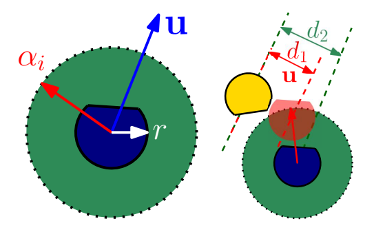
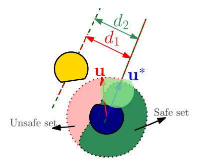
The algorithm is illustrated on Figs. 8, 9 and 10. Fig. 8 represents the admissible control space, which is the set of all feasible control commands for the robot. Since our robot is omnidirectional, the control space contains all velocities limited to a maximum speed $\alpha_i$. In the presence of an obstacle (Fig. 9), if the robot moves using an unsafe velocity ($\mathbf{u}$) it will lead to a collision. The PrSBC calculates the optimum velocity ($\mathbf{u}^$) which is as close as possible to the desired velocity ($|\mathbf{u}_i - \mathbf{u}_i^|^2$) and is inside the safe set, which is limited by the inter-robot ($S_u^{\sigma}$), inter-obstacle ($S_u^{\sigma_o}$) and amplitude ($\alpha_i$) constraints (Fig. 10).
The implementation of the PrSBC was in C++, and the QP was solved using the OSQP library [10]. In [11] it is possible to see a standalone implementation, and it can also be seen in our strategy software [4].
Two experiments were made to benchmark the algorithm. Results have shown that the PrSBC is capable of completely avoiding collisions in the antipodal test [9] when all robots are using the algorithm, and it reduces by roughly 97% the number of collisions when compared to not using the PrSBC. The corresponding test scenario was composed of 16 allied robots randomly moving in the field while 16 opponent robots were trying to block their paths. The algorithm also has an extremely low computational cost, which allows it to run at more than 300 cycles per second in a 9th gen i7 processor running on Ubuntu 20.04. More details can be seen in [12].
However, we had to implement a few changes to use the algorithm for an SSL match. Since there are many situations where the robot must be close to another obstacle, e.g., to dispute a ball or a position in the field, either the obstacle avoidance has to be turned off, or the safety radius (Ri) has to be lowered, otherwise the robot will be "afraid" to go the ball or to mark an opponent. Our choice was to have a dynamic safety radius, then, if an obstacle is too close, our robot might still want to avoid the collision. Further testing is needed to see if this is indeed the best approach.
The dynamic radius was implemented taking into consideration the current speed of the robot as follows:
$$R_i = \begin{cases} 0.15, & \text{if } v_i > 0.1\ 0.09, & \text{otherwise} \end{cases}$$
Ri is the safety radius in meters and v^i is the speed of the robot i in meters per second.
4 Path Tracking
The Small Size League is an high-dynamic league that requires a precise path tracking algorithm to avoid crashes since the team can be punished with a foul depending on the impact between the robots. Besides that, the robots need to be able to complete plays on a match since any position error can ruin a move.
Path tracking goal is to minimize the lateral error between the path planned and the path made by the robot. Furthermore, path tracking limits the direction input to generate smooth motion to maintain the robot's stability.
So, the RoboFEI team decided to test the use of the Linear Quadratic Regulator (LQR) and compare it with a PID controller, which is popular because of its simple implementation.
In this case, an omnidirectional robot of the Small Size League is used, Fig. 11 presents its kinematic model, and Equation 5 shows its equations, where X and Y are the field's references frames, x and y are the robot's position, v^x and v^y are the robot's local velocities, θ is the angle between robot's orientation and X axis and ω is the angular velocity.
$$\begin{cases} X = \int \dot{x} dt \ Y = \int \dot{y} dt \end{cases} \begin{cases} \dot{x} = v_x \sin(\theta) + v_y \cos(\theta) \ \dot{y} = -v_x \cos(\theta) + v_y \sin(\theta) \ \dot{\theta} = \omega \end{cases}$$
The LQR is a type of control based on optimal control theory and solves the stability problem of a system with minimum cost [13]. Considering a linear plant model based in state-space in the Equation 6, where A is the state matrix, x is the state-space vector, B is the control matrix and u is the control vector, the LQR control consists in the feedback control, where K is the gain matrix.
$$\dot{\mathbf{x}} = A\mathbf{x} + B\mathbf{u} \qquad \qquad \mathbf{u} = -K\mathbf{x}$$
The objective of LQR is to find an optimal vector u, called u ∗ , that minimizes the Equation 7, where Q and R are weighting matrices for the states variables and the control effort, respectively. Q and R need to be greater than zero.
$$\mathbf{u}^* = argmin \int_0^\infty (\mathbf{x}^T Q \mathbf{x} + \mathbf{u}^T R \mathbf{u}) dt$$
To find the gain matrix K it is necessary to solve the algebraic Riccati equation, as it is described in [14].
Equation 8 defines the matrices A and B, and vectors x and u used for the path tracking control in this paper, where x, y, $\theta$ and v are the robot's position in X and Y axes, orientation and velocity, respectively, while $sp_x$, $sp_y$, $sp_\theta$ and $sp_v$ are the set points of the robot's position in X and Y axes, orientation and velocity, respectively, and $a_v$ is the acceleration used to modify the robot's total velocity module.
$$A = \begin{bmatrix} 1 & 0 & 0 & 0 \ 0 & 1 & 0 & 0 \ 0 & 0 & 1 & 0 \ 0 & 0 & 0 & 1 \end{bmatrix} \quad B = \begin{bmatrix} dt & 0 & 0 & 0 \ 0 & dt & 0 & 0 \ 0 & 0 & dt & 0 \ 0 & 0 & 0 & dt \end{bmatrix} \quad x = \begin{bmatrix} x - sp_x \ y - sp_y \ \theta - sp_\theta \ v - sp_v \end{bmatrix} \quad u = \begin{bmatrix} v_x \ v_y \ v_\theta \ a_v \end{bmatrix}$$
LQR minimizes the errors calculated between the robot's states and its set points to zero these errors.
The matrices Q and R were tuned manually after some tests in the league's software called grSim [15] aiming for an optimal response ensuring the robot's stability when tracking a path. As said in [13], there are no established methods for selecting the values of parameters Q and R. Considering it, Equation 9 shows the Q and R matrices used in this paper.
$$Q = \begin{bmatrix} 1 & 0 & 0 & 0 \ 0 & 1 & 0 & 0 \ 0 & 0 & 1 & 0 \ 0 & 0 & 0 & 1 \end{bmatrix} \quad R = \begin{bmatrix} 0.01 & 0 & 0 & 0 \ 0 & 0.01 & 0 & 0 \ 0 & 0 & 0.04 & 0 \ 0 & 0 & 0 & 0.01 \end{bmatrix}$$
Besides that, in that case, the PID controls the robot position using one PID for each robot axis (X, Y, and rotation). Equation 10 shows the values of the respective PID gains for each axis. The gains of the controllers were tuned using the PID Tuner Toolbox of MATLAB.
$$\begin{cases} X \text{ axis } \to k_p = 1, k_i = 0.0631, k_d = -0.608 \ Y \text{ axis } \to k_p = 1, k_i = 0.169, k_d = -0.0169 \ \text{Rotation axis } \to k_p = 0.6, k_i = 0, k_d = 0 \end{cases}$$
In order to evaluate the behavior of LQR in high-dynamic environments and to compare the LQR with PID Controller, two tests were used with different speeds: a square-based path and a random-generated spline path. Fig. 12 shows the paths used. Each test ran 100 times for two each velocity, 1m/s and 2m/s.
The lateral error between the planned path and the true path; the error between the speed profile and the robot velocity; the error between the orientation profile and the robot orientation; and total navigation time are the metrics proposed to evaluate the test results. The mean of the 100 samples of each test was calculated.
Table 2 presents the results of the square-based path for both velocities.
Table 3 presents the results of the spline path for both velocities.
It's possible to see that, for the square-based path, the LQR controller had better results when analyzing lateral, speed, and orientation errors in both velocities. This shows that LQR is a better option in abrupt change of direction situations, although PID had a better result in lower speed when analyzing the total time mean. About the spline path, it's possible to conclude that LQR was better for speed and orientation errors in both velocities. However, PID was better in lateral error and total time for a lower speed. Besides that, the results also confirmed that the optimal controller has a poor factor, which is the non-linearity.
This study with the full results was published in 2023 Latin American Robotics Symposium (LARS) [6].
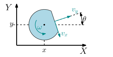
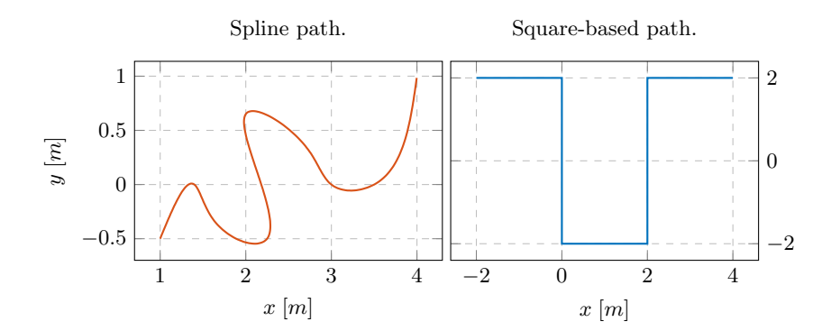
Table 2. Results of the square-based path for both velocities.
| Controller | Lateral Error (mm) | Speed Error (m/s) | Orientation Error (rad) | Total Time (s) |
|---|---|---|---|---|
| LQR with 1m/s | 23.186 | 0.0802 | 0.1513 | 17.581 |
| PID with 1m/s | 28.037 | 0.0909 | 3.4894 | 16.465 |
| LQR with 2m/s | 100.75 | 0.4778 | 0.6281 | 13.616 |
| PID with 2m/s | 109.54 | 0.8082 | 2.9583 | 22.086 |
Table 3. Results of the spline path for both velocities.
| Controller | Lateral Error (mm) | Speed Error (m/s) | Orientation Error (rad) | Total Time (s) |
|---|---|---|---|---|
| LQR with 1m/s | 31.226 | 0.0989 | 0.2417 | 9.5421 |
| PID with 1m/s | 29.297 | 0.1387 | 2.6779 | 8.4707 |
| LQR with 2m/s | 106.04 | 0.4638 | 0.7030 | 6.7151 |
| PID with 2m/s | 75.065 | 0.7184 | 3.4753 | 8.6657 |
5 Conclusion
In conclusion, the improvements reached last year in our path planning and path tracking algorithms, the study made about the chip kick efficiency, and the in-progress corrections in the V2023 mechanics, besides the good results of the electronics design, will help RoboFEI's goal of moving to Division A in RoboCup 2025.
5.1 Acknowledgements
We would like to thank, in advance, the Small Size League Committee, for the consideration of our material. We would also like to immensely thank the staff of Centro Universitario FEI, for all the help we always received from them.
References
- Alvaro D. Neto, Andre L. Marques, Bruno B. Correa, Felipe E. C. de Mello, Guilherme M. R. Kashihara, Guilherme W. Cardoso, Henrique B. Simoes, Joao V. L. Aguiar, Leonardo da S. Costa, Nityananda V. Saraswati, Rafael M. Cukier, Thiago O. Aravena, Flavio Tonidandel, Plinio T. A. Junior, and Reinaldo A. C. Bianchi. Robofei 2023 team description paper. 2023.
- Felipe Fill Cardoso, Eduardo M. Nottolini, Vitor Hugo Beck, Rodolpho L. Felizatti, Felipe Camargo, Erivelton G. dos Santos, Feliphe G. Galiza, Victor Torres, Milton Cortez, Jose Angelo Gurzoni Jr., Reinaldo A. C. Bianchi, and Flavio Tonidandel. Robofei 2012 team description paper. 2012.
- Henrique Barros Simoes, Guilherme Kashihara, Leonardo Da Silva Costa, and Flavio Tonidandel. Optimizing a chip kick module of a Small Size League robot. In 2023 Latin American Robotics Symposium (LARS), 2023 Brazilian Symposium on Robotics (SBR), and 2023 Workshop on Robotics in Education (WRE), pages 170 – 175, 2023.
- RoboFEI-SSL. Robofei small size league gitlab. https://gitlab.com/robofei/ssl, 2021. [Online; accessed 1-Fev-2024].
- Katsuhiko Ogata et al. Modern control engineering, volume 5. Prentice hall, Upper Saddle River, NJ, 2010.
- Joao Victor Lourenco Aguiar, Leonardo Da Silva Costa, and Flavio Tonidandel. Linear Quadratic Regulator Path Tracking for Omnidirectional Robots in High-Dynamic Environments. In 2023 Latin American Robotics Symposium (LARS), 2023 Brazilian Symposium on Robotics (SBR), and 2023 Workshop on Robotics in Education (WRE), pages 266–271, 2023.
- Leonardo da Silva Costa and Flavio Tonidandel. Comparison and Analysis of the DVG+ A* and Rapidly-Exploring Random Trees Path-Planners for the RoboCup-Small Size League. In 2019 Latin American Robotics Symposium (LARS), 2019 Brazilian Symposium on Robotics (SBR) and 2019 Workshop on Robotics in Education (WRE), pages 1–6. IEEE, 2019.
- Leonardo da Silva Costa and Flavio Tonidandel. DVG+A* and RRT Path-Planners: A Comparison in a Highly Dynamic Environment. Journal of Intelligent & Robotic Systems, 101(3):1–20, 2021.
- Wenhao Luo, Wen Sun, and Ashish Kapoor. Multi-robot collision avoidance under uncertainty with probabilistic safety barrier certificates. Advances in Neural Information Processing Systems, 33:372–383, 2020.
- B. Stellato, G. Banjac, P. Goulart, A. Bemporad, and S. Boyd. OSQP: an operator splitting solver for quadratic programs. Mathematical Programming Computation, 12(4):637–672, 2020.
- Leonardo da Silva Costa. Robot navigation algorithms. https://gitlab.com/leo_costa/RobotNavigation, 2023. [Online; accessed 1-Fev-2024].
- Leonardo Da Silva Costa and Flavio Tonidandel. Multi-Robot Path Planning with Safety Based Control applied to the Small Size League Robots. In RoboCup 2023: Robot World Cup XXVI. Springer Cham, 2023.
- Franciszek Dul, Piotr Lichota, and Artur Rusowicz. Generalized linear quadratic control for a full tracking problem in aviation. Sensors, 20(10), 2020.
- J. Nazarzadeh, M. Razzaghi, and K.Y. Nikravesh. Solution of the matrix riccati equation for the linear quadratic control problems. Mathematical and Computer Modelling, 27(7):51–55, 1998.
- Valiallah Monajjemi, A. Koochakzadeh, and S. S. Ghidary. grsim robocup small size robot soccer simulator. In RoboCup, 2011.