RoboJackets 2024 Team Description Paper
Prabhanjan Nayak, Mili Das, Sid Parikh, Nathaniel Wert, Kelvin Hau, Saihari Kota
Georgia Institute of Technology
Abstract This paper describes the improvements implemented by the Georgia Institute of Technology's RoboCup SSL team, RoboJackets, in preparation to compete in RoboCup 2024 in Eindhoven, Netherlands. Mechanical modifications attempted to improve the control and motion profile. A firmware rewrite and a control board redesign were established in an effort to modernize a standard embedded system. Our software changes resulted in a refined strategy that built on the agent-based principle. As always, all of our designs and code are open-sourced. See the RoboCup SSL website for links, or search for "RoboCup" on our GitHub page.
1 Mechanical
After competing in RoboCup SSL 2023, it was apparent that many of the robot's mechanical subsystems were outdated compared to the other teams in the league. As such, three major modifications were made to our mechanical design. Our dribbler was redesigned to improve the damping system and improve ball reception. In addition, our wheels were modified to increase points of contact with the ground and improve robot motion. Finally, our shell and color plate parts were modified to facilitate troubleshooting and access to interior electronics.
1.1 Dribbler
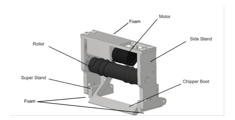
A major issue with the 2023 robot was poor ball control. The robot was unable to consistently manipulate the ball due to the ball bouncing off of the dribbler. Even when the ball was within the robot's control, there were issues retaining control of the ball with minimal movement. These issues were mainly attributed to the poor usage of damping and insufficient degrees of freedom within the 2023 dribbler design. The design had a single rotational degree of freedom, as shown in Figure 1.
1.1 Dribbler (continued)
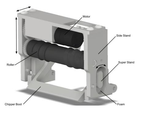
It was dampened via foam underneath and behind the side stands which provided the rotational degree of freedom. This was chosen at the time to ensure that the degree would not excessively rotate; however, this resulted in an over dampened system where the dribbler barely rotated upon impact from the golf ball. As a result, the ball would ricochet off the dribbler subsystem due to the poor usage of damping. Furthermore, the single rotational degree of freedom seemed inadequate. To address these issues and improve our ball control and passing, the dribbler subsystem was redesigned to incorporate multiple degrees of freedom and better usage of damping. The 2024 dribbler shown in Figure 2 has 3 degrees of freedom. This is made possible by the elliptical cutouts within the side stands and elliptical extrusions on the super stands. The gap between the elliptical slots and extrusions are filled with Poron Microcellular Urethane foam. The dribbler is dampened in all degrees of freedom while still allowing the dribbler to move freely. This design retains the rotational degree of freedom from the previous design while adding two translation degrees of freedom, allowing the dribbler to move in several ways in response to impact from the ball. Furthermore, due to the vertical movement of the dribbler, a clamping phenomenon was made possible with the new dribbler design, similar to the one described by TIGERs in their 2022 TDP [1]. The dribbler moves up upon impact from the ball and moves down onto the ball to essentially clamp it vertically, but not laterally.
Even when this does not occur, the new dribbler subsystem is better equipped to deal with faster passes. The 2024 dribbler design was tested against the 2023 design in a basic test designed to observe ball reception when the dribbler motor is not active. At a fixed distance, the rate of success, defined by the ball staying within a 25mm radius of the dribbler after hitting the dribbler, and the rate of the clamping phenomenon were recorded between the old and new designs. The old dribbler had a 30% success rate and never exhibited the clamping phenomena as shown in Table 1. The new dribbler was deemed successful 75% of the time and clamped the ball 45% of the time.
1.2 Wheel
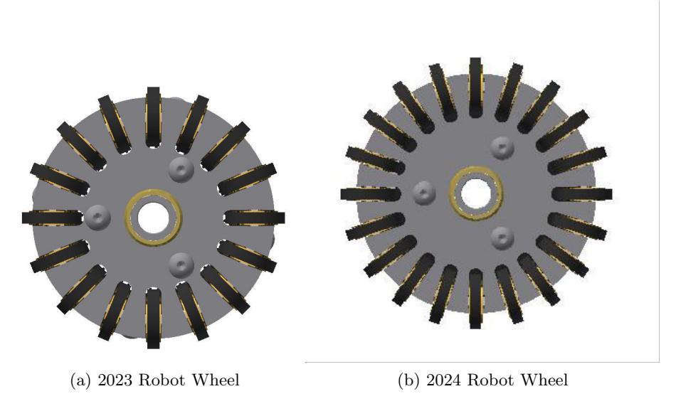
At competition, the 2023 robot was observed to have excessively large vertical and horizontal vibrations when moving. Teams such as TIGERs or ZJUNlict [2] [3], had comparatively smoother motion. Upon further inspection, the main difference in the mechanical design was the design of the omniwheels. The 2023 robot wheels had 16 rollers whereas teams with smoother motion had 20 rollers. Keeping this in mind, the 2024 robot has redesigned wheels with 20 rollers. This ensures that the wheel is in contact with the ground much more frequently than the previous wheel design with 16 rollers. As shown in Figure 3, the addition of roller resulted in the overall diameter of the wheels had to be increased from 50mm to 53mm.
1.3 Color Plate and Shell
The color plate and shell were modified this year to improve access to robot interiors and display more information for debugging. In 2022, shells were manufactured for the robots. However, it was discovered that the shells were designed to be exactly 0.15m tall. Due to a slight offset in height from the baseplate to the ground, the overall robot height was closer to 0.16mm. Furthermore, LEDs on the control board meant to display status information were covered up by the shell. Last year, these issues were fixed by cutouts and trimming the overall height. This year, we desired a more systematic approach to the shell modifications, so a shell jig was 3D-printed with the intended height and cutouts so that creating these cuts would be more efficient.
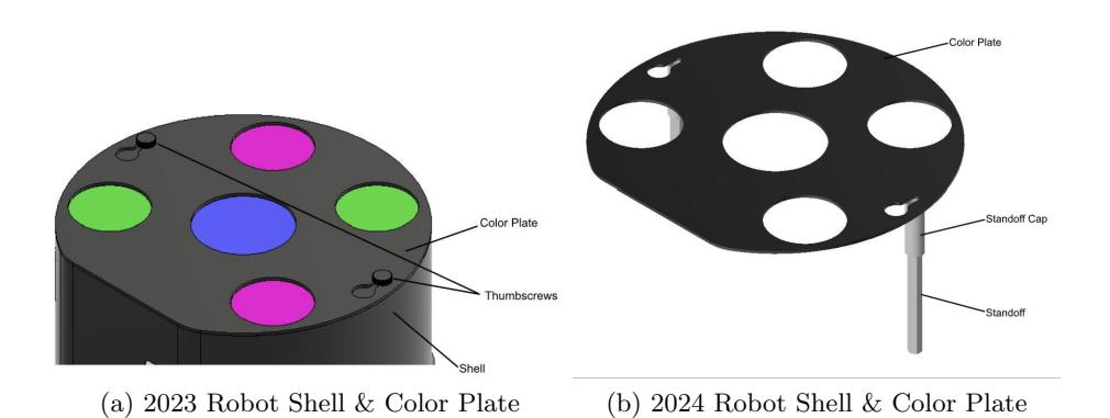
Another issue with the previous color plate and shell design was that the color plate was fixed onto the shell via two thumbscrews and two standoffs as shown in Figure 4. These thumbscrews, while easy to remove, added to the time required to take off the shells or switch color plates. As such we opted for a magnetic design as shown in Figure 5. Custom standoff caps were designed to house a magnet at the top. Likewise, magnets were attached to the color plates such that color plates could easily be put on and taken off of robots. This eliminates the need for screws of any kind in this subassembly.
2024 Robot Specification
| Dimension | ∅180mm x 146mm |
|---|---|
| Total Weight | 2.59 kg |
| Drive Motors | Maxon EC 45 Flat (651610) |
| Encoders | Maxon Encoder (673029) |
| Wheel Diameter | ∅53mm |
| Dribbler Motor | Maxon EC 16 (405812) |
| Dribbler Bar Diameter | 15 mm |
| Dribbler Damping Material Poron Microcellular Urethane | |
| Kicker Charge | 4000µF @ 250V |
| Kick Speed | 6m/s (max speed) |
| Chip Distance | approx. 3m |
2 Electrical
This year's electrical changes revolve around the microcontroller unit (MCU) and the radio. For the MCU, we have transitioned from mTrain to the Teensy 4.1 (Refer to Section 3.1). For the radio, we switched from a 2.4 GHz Wi-Fi system to a 868-915 MHz LoRa/FSK system. Both of these changes also involved a revision to our current Control Board v3.4, which resulted in the new Control Board v3.5. Aside from changes to our boards, we have also switched our current batteries to the Tattu R-Line V1.0, which offers of much higher C rating of 90C over our previous 45C, for better charge and discharge performance. The following table summarizes the major updates to our electrical system:
Electrical Stack
| 2023 | 2024 | |
|---|---|---|
| Radio | ISM43340 | RFM95W |
| Base Station | N/A | Raspberry Pi 4 + RFM95W |
| Microcontroller | mTrain | Teensy 4.1 |
| Control Board | v3.4 | v3.5 |
| Kicker Board | v3.3 | v3.3 |
| Battery | 18.5V 45C 2200 mAh | 18.5 90C 1600 mAh |
2.1 Radio
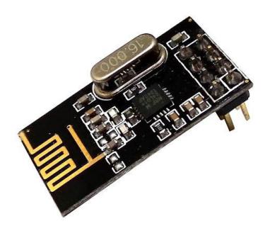
Since 2019, our wireless communication has been achieved through the ISM43340 2.4 GHz Wi-Fi chip. The main advantage of it was the abstraction offered by the Wi-Fi protocol. However, this also came with the drawback of not having control over how information is modulated and sent from the access point to the robot and vice versa. In an effort to improve our wireless system, our team designed multiple iterations of boards utilizing the ISM43340. Unfortunately, up until 2022, our team was still facing the same common problems, high latency and packet loss. For 2023, we decided to finally switch out of our Wi-Fi based wireless communication. We experimented and tested with the following radio breakout boards: the nRF24L01, and the RFM95W. Both transceiver modules are interfaced using the SPI protocol.
Each radio offers a different set of pros and cons. On one hand, the RFM95W is based on Semtech's SX1276 radio, which allows for a Sub-GHz operating frequency (868 - 915 MHz) and uses the LoRa/FSK modulation techniques. On the other hand, the nRF24L01 operates on a 2.4GHz ISM frequency band. In theory, the RFM95W is capable of achieving a maximum bit rate of 300 kbps, while the nRF24L01 is capable of a much higher 2 Mbps. One advantage of the RFM95W is the LoRa modulation, which provides a much more stable transmission through the use of explicit headers and CRC validation.
Our team has decided to move forward using the nRF24L01 as our primary radio module, but keep the SX1276 as a backup module. Aside from the raw performance of each radio module, we must also consider how the central endpoint's constant stream of sending and receiving of packets is handled. A detailed explanation about this central end-point is given in the next section. For now we'll refer to it as our base station. Because we expect the our base station to be our main point of communication between our software and the robots on field, it must be capable of servicing an amount of packets equivalent to at least twice the amount of robots, at a specified frequency. The frequency being determined by how fast we're sending updated commands to the robots, not to be confused with operating frequency, which in the case of the nRF24L01 is 2.4 GHz. We are expecting the nRF24L01 to be much more capable of handling the higher number of transmissions required with much less on-air transmission delay. In order to prove that we can indeed achieve our desired performance, we decided test our two radios under the same round-trip transmission delay testing. We effectively sent a packet from one end-point to the other, processed the packet, and sent a reply back to the original sender. The packet being sent contained the same number of bytes as a packet that would be sent on an actual match. The results are summarized in the following table:
Radio Round-Trip Latency Test Results
| Radio | Average (ms) | Min (ms) | Max (ms) |
|---|---|---|---|
| nRF24L01 | 0.70 | 0.50 | 3.00 |
| SX1276 | 33.0 | 31.0 | 34.0 |
2.2 Base Station
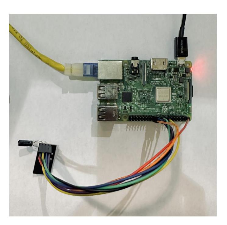
This section is meant to provide a general overview of the hardware in our base station. Wi-Fi provided a great abstraction to how packets were managed to and from our software: we simply relied on a wireless access point and a router. With the adoption of our new wireless communication system, we have had to develop our own base station unit. The base station allows for communication between the transceivers on the robots and our software. Our base station was made using a Raspberry Pi 4 and two transceiver modules. The Raspberry Pi offers a great abstraction to managing Ethernet packets to and from our software, while also offering the SPI protocol required to control the transceivers. More information on the implementation/firmware of our base station can be found in Section 3.4.
2.3 Control Board
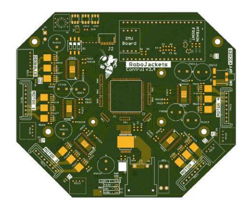
As specified above, the Control Board has been under a revision from v3.4 to v3.5. Most of the changes done were mainly to adjust for the new radio and MCU pinout and layout. The remaining changes revolve around an updated battery connector, XT-60, and updated motor connectors. One last notable change is the slight adjustment of digital signal traces such as SPI, I2C, and FPGA signals following on Altium Academy guide [4] on better PCB design practices.
3 Firmware
This year's firmware team began the process of migrating our codebase from C++ to Rust following a change in microcontrollers. The team also switched from using WiFi for communication with the robots to RF radio, which necessitated the creation of a base station to relay packets to the robots.
3.1 Microcontroller
In 2019, the team designed a Mbed based microcontroller referred internally as MTrain. MTrain may have originally represented a significant advancement over the previously used microcontroller. However, much of the documentation and functionality of the microcontroller have been seemingly lost to time with all members involved in its design and firmware having departed the team. To enable future firmware development, the team has decided to abandon MTrain in favor of an off-the-shelf microcontroller. The selected microcontroller is the Teensy 4.1. The Teensy 4.1 utilizes an ARM Cortex-M7 processor running at 600MHz making it a suitable replacement for MTrain [5] (which also utilized an ARM Cortex-M7 processor). A driving factor in the teams choice of the Teensy microcontroller is its large presence in the hobby and open source embedded systems community. This meant that a large amount of the necessary tooling for the microcontroller was ready off-the-shelf which has helped the team to decrease the learning curve associated with helping new members to utilize the microcontroller.
3.2 Rust
With changing microcontrollers, we also faced the challenge of having to rewrite a large amount of the codebase. Previously, our firmware stack was written in C++ utilizing FreeRTOS, but the stack was riddled with deadlocks and errors that made debugging and working with the stack virtually impossible. Therefore, the team has decided to migrate as much of the previous codebase to utilize Rust.
Rust is commonly praised for its approach to memory management, but its use in embedded systems development often gets overshadowed. Mainly, Rust and its community, rigorously follows a test-driven development model where testing modules are first-class parts of the language. This test-driven model has proven incredibly useful when debugging issues that arise in robot firmware by allowing a vast suite of tests to debug individual drivers and behaviors of the robots.
Another benefit and driving factor behind the decision to utilize Rust for the firmware rewrite is the language's built-in package manager and simple build manager, Cargo. Cargo allows external dependencies to be added to Rust projects through a Cargo.toml file that specify dependencies and versions. In theory, this allows a very collaborative development process with Rust projects where multiple contributors enforce a standard within Rust projects. One such example is the development of the embedded-hal. The embedded-hal is a unified hardware access layer library that enables the development of embedded device drivers that are microcontroller agnostic [6].
With the new firmware rewrite, the team's goal was to utilize as many tested community-developed drivers. Ideally, this would exponentially decrease development time while maintaining a high level of performance by relying on the work of more experienced engineers. Unfortunately, the current Rust ecosystem is still developing in the embedded sphere and a large number of community drivers were lacking in features and/or testing. However, the testing features mentioned earlier have enabled the team to make separate tests for each driver, ensuring their functionality.
Rust also makes use of an incredibly strict type system. In combination with the embedded-hal, this means that it becomes incredibly difficult to misuse peripherals when designing drivers. As an undergraduate team with a consistently rotating roster, this compile time type checking should help future advancements to avoid common pitfalls and errors.
3.3 RTIC
In addition to migrating our codebase from C++ to Rust, the team also employed the use of a new RTOS. Specifically, the team is now utilizing the Real-Time Interrupt-drive Concurrency (RTIC) RTOS [7]. In short, RTIC utilizes hardware interrupts and static priority to schedule tasks and ensure deadlock-free performance. The main driving factor behind this decision was RTIC's Stack Resource Policy that enables deadlock and race condition debugging at compile time. Being able to diagnose deadlocks, in particular, at compile time should save the team a vast amount of time once the software is written.
3.4 Base Station
Previously, the team utilized 5Ghz Wi-Fi to communicate with robots. At the previous competition, the team had various issues with the Wi-Fi router and access point, which has motivated the team to switch from utilizing Wi-Fi to RF radio. In switching to RF radio, a solution had to be implemented to relay packets from the base computer to the robots.
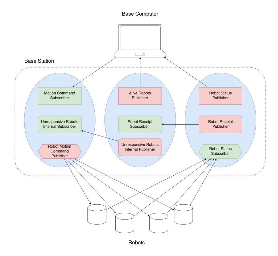
The RoboJackets base station consists of a Raspberry Pi 4 connected to 2 nRF24L01+ radio modules. One of the modules is configured to be constantly listening to incoming packets and other is designated to send packets to the robots. The main functionality of the base station can be broken down into a diagram as follows:
The left-most process represents a constantly running node that conglomerates incoming UDP transmissions from the base computer and sends the commands to the robots. Currently, the messages are sent to the robots one after the other every 50 miliseconds; however, future research is necessary to perfect this timing. The middle process represents a timeout checker node. The timeout check receives a robot id and timestamp from the right-most process and performs a routine timeout check every 500ms where robots who have not responded during the allotted time frame are considered unresponsive. A list of the responsive robots is then sent to the base computer so the strategy stack can compensate for disconnected robots. By separating the various radio functions into separate distinct blocks, the base station can achieve minimal delay when handling incoming and outgoing data.
Originally, the team wanted to utilize a RFM95 radio. The RFM95 radio utilizes the 915 MHz frequency to send packets. After testing, the minimum round trip delay for sending packets in idealized conditions was 32ms. Extrapolating this from one robot to multiple robots, means that, in an ideal world, sending and receiving packets from the robots one after the other would cost 192 ms. However, at competition, the team experienced increased latency with the previous Wi-Fi setup so the real-time latency of sending messages to robots will likely increase significantly. The RFM95 radio also had no support for address filtering when in LoRa mode, which means that every robot had to spend clock cycles validating the contents of incoming messages.
Due to these latency issues, the team has decided to switch to the commonly used nRF24L01+ module, which at 1 Mb/s can reliably deliver worst-case round trip times of 3 ms in our lab setup. Therefore, the team has decided to utilize the nRF24L01+ as the radio of choice for our robots.
The base station codebase is open source and written in Rust, utilizing the open source ncomm communication framework [8] for inter-process communication.
4 Software
The primary goals for our software this year were:
- (On-field) Become fully compliant with kicking rules
- (Architecture) Refactor path planners so they are knowledgeable and composable
- (On-field) Further develop offensive strategy, including repeatable passes
- (Architecture) Finish transition to agent-based model of strategy
Goal 1 was achieved with the help of Goal 2, and likewise for 3 and 4.
4.1 Refactoring Path Planners
Upon further inspecting the architecture of the planning stack, the bug was identified that had plagued us for the 2023 competition: the planner was designed to manually ignore the "obstacle" related to the ball, since the ball needed to be kicked, but that resulted in ignoring the ball during STOP as well.
Thus, the planning interface was modified so that planners require knowledge of the current referee command and/or game state (internally represented as "PlayState").
Additionally, it was identified that many planners often repeated code. Our most basic path planner, "path target path planner," simply plans a path to a desired ending point and ending velocity. Many other planners model this behavior, but with more specific goals. For example, the faulty "line kick" path planner would draw a path from the robot to a ball. To improve the lack of repetition and reduce the number of easy bugs, path planners needed to be refactored so that they are composable: one planner may delegate to another for all or part of its execution.
4.2 Kicking Rules Compliance
Motivation During the 2023 SSL competition in Bordeaux, RoboJackets incurred several penalties for touching the ball during the STOP state. Additionally, a goal was discounted for kicking the ball above the maximum allowed speed.
Both of these errors were attributed to a faulty path planner for "line kicking", i.e. driving up to the ball with velocity to kick it straight ahead.
Implementation Taking advantage of the new composable planners, the line kick path planner was rewritten. It has two stages, like before. Each stage delegates to the regular path target path planner with different parameters. The first step draws a path to approach the ball, moving around the ball to face the target of the kick if necessary. The second step drives into the ball with low velocity, allowing the robot to kick upon hardware detection of the ball.
4.3 Offensive Strategy
Motivation At RoboCup Bordeaux 2023, our offense was a relatively simple "shoot-only" strategy. Though we had software support for passing, issues with accurate motion control precluded reliable on-field passes.
The goal for the 2024 competition was to expand our offensive strategy to reliably pass when a robot is pressured, and prefer passing to shooting when far from the goal.
Implementation To refine the passing ability of our robots, a few abilities have been added:
- Broadcast to all other agents the request to send a pass When a robot has possession of the ball, if it does not have a clear shot, it now can broadcast to all other robots the desire to get rid of the ball. This is an improvement to the previous request format to send a pass to a specific robot.
- Each agent can calculate if it is "open" enough to receive a pass This function draws a vector from the ball to the agent and ensures no robots are on this line, nor any opposing robots are close enough to make an interception.
- Passer can calculate the ideal speed at which to kick the ball. This function calculates the distance of the pass and uses a kinematic equation to calculate the speed at which to kick the ball. This function has been adapted from our former Python gameplay code, and is also based on a TIGERs eTDP from 2019 [9].
- Note that this functionality is not currently supported by our hardware/firmware
4.4 Agent-Based Strategy Architecture
Motivation As outlined in our 2023 TDP, last year was a year of sweeping architectural changes to the software stack. The ST(R)P model was replaced with an agent-based approach to strategy, similar to that of ER-Force's software architecture. Additionally, the Python portion of our stack (implementing strategy) was eliminated; hence the need to re-create most of the strategy over the past two years.
Last year, the individual agents were created as ROS ActionClients, which communicated desired robot actions to a central planning ActionServer, which handled path planning and trajectory generation for each robot.
The need for some communication between agents is apparent. Two systems were implemented in 2023. One was the separate coach, which is somewhat equivalent to ER-Force's "Trainer" [10]. This was implemented as a plain ROS node publishing instructions to a topic. The second was an inter-agent asynchronous communication system implemented with ROS services.
The first system was simple and effective but deemed ultimately unnecessary. The coach would communicate position assignments: instructing agents to play Offense, Defense, or Goalie. It would make adjustments based on possession.
The problem arose with special situations such as free-kicks, penalty-kicks, and kick-offs. It wasn't immediately natural for the coach to assign a kicker and instruct other agents to play defensively or move away, etc. There are many solutions to this problem. In 2023, the coach would assign specialty positions: for example, robot 1 might be assigned to be PenaltyKicker and the rest Defense. This was a functioning implementation of the strategy pattern, but the nature of ROS nodes meant that the coach had to communicate with agents through lowlevel constructs like enums and strings, as opposed to more meaningful constructs like a Behavior/Position itself.
In 2024, the decision was made to remove the coach and allow decisions to happen within the agents themselves. Thus the choice of position/behavior/role happens without going through ROS, so to speak. Any inter-agent coordination can still happen through the second system mentioned previously, which continues to function efficiently.
Implementation Previously, the ROS ActionClients (representing the agents) would create a position class of some derived type, decided by the coach.
This has been refactored so that all agents create the same class, removing the need for the coach. This new class, which was called RobotFactoryPosition, implements the strategy pattern in a more readable way. It does three things:
- Each agent decides its own position
- State information from the ActionClient is relayed to the position
- Desired robot actions are returned
Upon meeting conditions, the position's derived implementation can be swapped out at any time, thus implementing the same strategy pattern as before, but far more semantically.
Additionally, since this new class operates exactly where Offense, Defense, and Goalie used to operate, it can also communicate with other agents (which are all instances of the same class). This allows for inter-agent negotiation situations such as free-kicks. The agents can decide together which robot should kick the ball and assign specialty positions as necessary.
5 Open Source
RoboJackets continues to open source all aspects of development. Links to software, electrical, and mechanical materials can be found on the RoboCup SSL website [11], or by searching for "RoboCup" on our GitHub page.
References
[1] Mark Geiger Nicolai Ommer Andre Ryll. TIGERs Mannheim - Extended Team Description for RoboCup 2022. 2022. [2] Sabolc Jut Andre Ryll. TIGERs Mannheim - Extended Team Description for RoboCup 2020. 2020. [3] Lingyun Chen et al. ZJUNlict Extended Team Description Paper for RoboCup 2018. 2018. [4] Altium Academy PCB Design Guides. url: https://education.altium.com/ [5] Teensy 4.1 Specifications. url: https://www.pjrc.com/store/teensy41.html [6] Rust Embedded Hal. url: https://docs.rs/embedded-hal/latest/embedded_hal/ [7] Real-Time Interrupt-driven Concurrency (RTIC) framework. url: https://rtic.rs/2/book/en/ [8] ncomm. url: https://docs.rs/ncomm/0.4.1/ncomm/ [9] Mark Geiger Nicolai Ommer Andre Ryll. TIGERs Mannheim - Extended Team Description for RoboCup 2019. 2019. [10] A. Wendler C. Lobmeier D. Burk and B. Eskofier. ER-Force - Extended Team Description for RoboCup 2018. 2018. [11] Open Source Contributions. url: https://ssl.robocup.org/open-source-contributions/