RoboTeam Twente Extended Team Description Paper for RoboCup 2024
Bas van der Kaaden, Chris Krommendijk, Csongor Buzogany, Dario Capitani, George Ayad, Greg Ward, Jan Geert Kroijenga, Jonathan Willigers, Jorn de Jong, Juan José González Torres, Julie Muchembled, Leonie Hoekstra, Luuk Winters, Mihnea Razvan Petrea, Moustafa Mahmoud, Prawin Kumar Srinivasa Kumar, Robin Roetenberg, Simone Tollardo
University of Twente (UT), Enschede, the Netherlands; Saxion University of Applied Sciences, Enschede, the Netherlands; RoboTeam Twente, Capitool 25 Enschede, the Netherlands
Abstract RoboTeam Twente has participated in the Small Size League of the RoboCup for the past seven years. To help progress the current state of the competition the main innovations are outlined each year. This paper showcases the custom solenoids, direct drive system, the new front assembly, and the new PCBs along with the new communication system between them. Additionally, this paper will present our findings and tests related to the new flat solenoids.
1 Introduction
Students from the University of Twente and Saxion University of Applied Sciences make up the multidisciplinary team RoboTeam Twente. A group of students who wanted to push themselves in the robotics and artificial intelligence sectors created the team in 2016. Seven generations later, it is the responsibility of this year's team to advance the design of the preceding generations and further innovate the Small Size League (SSL) robots developed by RoboTeam Twente.
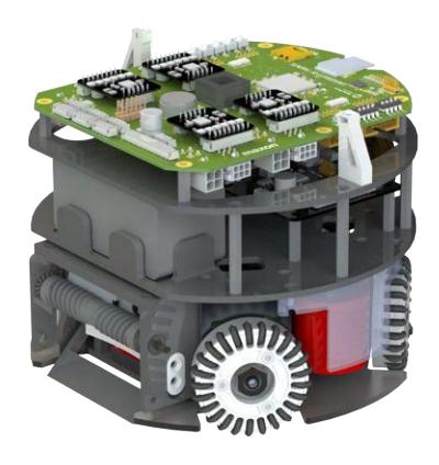
The modifications made to the hardware will be covered in this paper, starting with mechanics and finishing with electronics. An updated modular design was introduced two years ago [5], and it is expanded upon this year. A render of the robot from last year along with the render of the new robot described in this paper are shown in Figure 1 and Figure 2, respectively. The robot's specifications can be found in Table 1.
![Render of robot used at RoboCup 2023 [2].](/tdps/soccer_smallsize__2024__RoboTeam_Twente/_page_1_Picture_1.jpeg)
2 Hardware
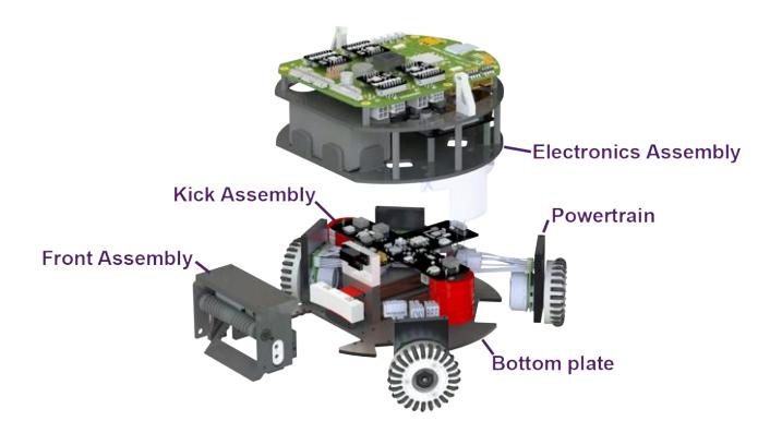
The hardware consists of all the physical components of the robot. This is divided into mechanical and electronic parts. In recent years, RoboTeam Twente (RTT) has been working on creating a more modular [5] and robust design of the hardware. This year's team will continue on that path by completely redesigning the hardware in order to improve the reliability of the robot. The exploded view of the new robot is shown in Figure 3. Details of the new design can be found on the wiki of RTT.
2.1 Mechanics
The reliability of the hardware has been a recurring challenge problem over the years. This year the mechanics subteam redesigned the entire robot to improve the reliability of our robot. This year the biggest changes are made in the transmission, kicking-chipping mechanism and ball-handling mechanism as described below.
Robot specifications comparison.
| Robot Version | v2023 | v2024 |
|---|---|---|
| Dimension | 179 x 149 mm | 179 x149mm |
| Driving motor | Maxon EC-45 flat 50 Watt | ECXFL32L 48V 50 Watt |
| Dribbling motor | Maxon DCX19S EB SL 24V | Maxon DCX19S EB SL 24V |
| Wheel diameter | 56 mm | 56 mm |
| Wheel gear ratio | 2:5 | 1:1 |
| Encoder driving motors | MILE 1024 CPT | MILE 2048IMP |
| Dribbling bar diameter | 10 mm | 14 mm |
| Dribbling bar length | 70 mm | 70 mm |
| Encoder dribbler bar | ENX10 EASY 1024IMP | ENX10 EASY 1024IMP |
| Dribbler gear ratio | 7:9 | 5:3 |
| Microcontroller | STM32F767ZI | STM32F767ZI |
| Ball sensor | zForce AIR Touch | Custom Infrared sensor |
| Motor driver | ROHM BD63002AMUV | TI DRV8323SRTAR |
| Inertial Measurement Unit | Xsens MTi-3-8a7g6t | Xsens MTi-3-8a7g6t |
| Battery | 6S1P 22.2V 150C LiPo | 6S1P 22.2V 150C LiPo |
| Kicker-and-chipper-board Capacitor | 680 µF; Working voltage 450V | 1000 µF; Working voltage 200V |
| Wireless Communication | SX1280 2.4GHz | SX1280 2.4GHz |
2.1.1 Direct Drive
Currently, the available space in the bottom assembly is limited and insufficient to improve the solenoid design and front assembly. These improvements are to increase the shooting and ball-handling skills of the robot. A solution to create sufficient space is to use smaller motors and reduce the space needed for the powertrain assembly. A way to solve the problem of reducing the space needed for the powertrain assembly is switching to direct drive, where the design is inspired by TIGERs Mannheim ETDP of 2020 [6].
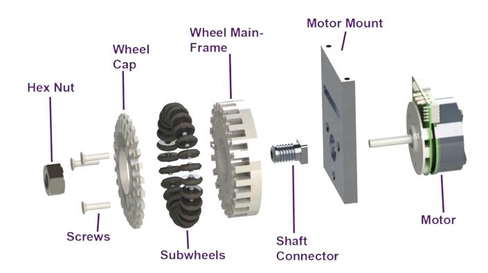
To switch to direct drive, a more powerful and smaller motor is needed. The more powerful motor makes the use of gears as a transmission redundant, because the torque delivered by the new motor is sufficient. This allows connecting the wheel directly to the motor shaft. An additional benefit of removing the gears is removing the backlash associated with the gears of the robot, which improves the control of the robot. A redesign of the powertrain was needed to accomplish the switch to direct drive as shown in Figure 4.
The power of the motor is transferred to the wheel with the use of a form fit. A shaft connector is designed and glued using Loctite 638 to the motor shaft to create the form fit. The shaft connector is the same idea as TIGERs Mannheim [6], however, the square is bigger to provide a bigger contact area to transfer the power. Furthermore, the omniwheel is redesigned, which has been used for the past seven generations. A square hole is added to the wheel main frame, in which the square of the shaft connector fits. Compared to the v2023 design, in which gears were used, this design will remove backlash associated with the gears.
Because the motors and the powertrain assembly are smaller, the wheel configuration can be changed. The configuration of the v2023 robot had an angle between the back wheels of 60 degrees and an angle of 120 degrees between the front wheels. The v2024 robot will still have an angle of 120 degrees between the front wheels; however, between the back wheels, there will be a 90-degree angle. The new angle configuration contributes to space creation for the solenoid assembly.
All of the changes result in more space at the bottom assembly. This allows for improving the solenoid and front assembly of the v2024 robot.
2.1.2 Solenoids
The current solenoids take up quite some space, especially vertically. For this reason the solenoid used for chipping cannot be placed conveniently. The bottom solenoid is used for kicking, its height is determined by the ball dimension and is therefore fixed. Due to the height of the round solenoids the chipping solenoid could not be placed underneath the kicking solenoid. However, the chipping plate is located beneath the kicker, thus the energy from the chipping solenoid needs to be transferred over quite some distance, which is not preferred. A solution is to switch from round solenoids to flat solenoids, where inspiration is gotten from the TIGERs Mannheim ETDP of 2020 [6]. This does allow for placing the chipping solenoid below the kicking solenoid. Furthermore, the new solenoids are designed to improve the reliability of the kicking-chipping system. This is needed because variations between different solenoids and kicker-chipper boards were observed. This is also discussed in RTT's 2023 ETDP[2].
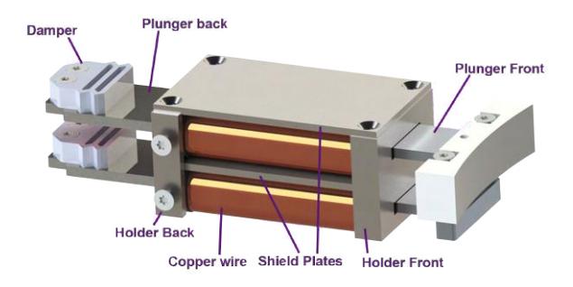
The design from TIGERs Mannheim is adapted to our needs. The new design is shown in Figure 5. One of the changes is to have a ferromagnetic metal case around the solenoid. This is done by changing the material of the holders from aluminium to steel with a high relative permeability. Additionally, at the bottom and the top of the solenoid, a steel plate is added. The material used is DIN 1.0503 steel, which is C45 carbon steel and has a magnetic permeability of around 200 (-) [10]. This will create a metal case, which concentrates the magnetic field more towards the centre of the solenoid. Therefore less electrical energy is needed to kick the ball at the same speed as compared when no shielding is used. Furthermore, the new kicker-chipper board will experience a less powerful magnetic field compared to when using no shielding because the field is more concentrated towards the centre of the core. This will help in preventing damage to the PCBs.
The new solenoid will make use of 0.5mm copper wire, has 6 layers and a total of 546 windings. This is wound around the coil, which is made from PETG. The reason for the 0.5 mm thickness is to increase the resistance of our solenoid, which ensures the solenoid does not exceed the maximum current the kicker-chipper board can handle. The resistance is calculated using the material properties of copper wire and verified using a multimeter put on resistance mode. It was concluded that this was within the limits of the kicker-chipper board.
2.1.3 Solenoid Testing
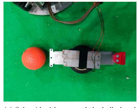
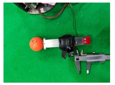
To validate the new shielding of the design and see the influence of the core offset of the plunger. Also, the difference between putting the ball directly against the plunger or having a set offset from the plunger is tested. To test these parameters an experiment is designed. The experiment consists of four scenarios, where every individual scenario has been tested three times and the average is taken. The different scenarios are shown in table 2. Two scenarios are shown in Figure 6, where Figure 6a represents #2 and Figure 6b represents #3. The test was done with a solenoid which consist of 0.6 mm copper wire, which had 5 layers and a total of 342 windings. It has a resistance of 20.5 (Ω) Furthermore, the specifications of the kicker-chipper used can be found in table 1, where the PCB of the v2023 robot is used.
The four scenarios of the solenoid experiment.
| Scenario | Metal Case | Ball offset plunger |
|---|---|---|
| #1 | Yes | 0 mm |
| #2 | Yes | 10 mm |
| #3 | No | 0 mm |
| #4 | No | 10 mm |
2.1.4 Solenoid Testing Results
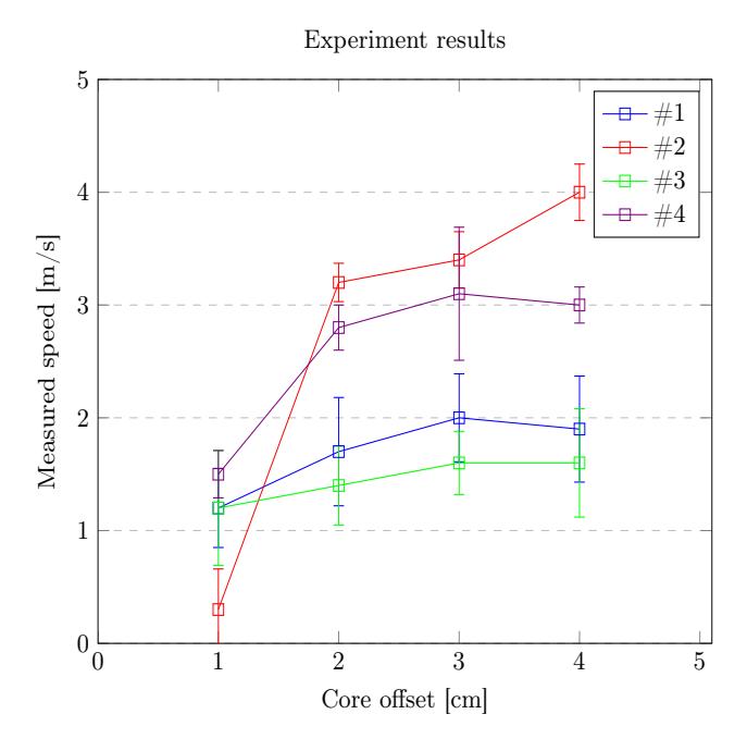
The results of the experiment are shown in Figure 7. It can be seen that increasing the core offset has the most impact on increasing the ball speed. Also, it can be seen that shielding the solenoid increases the ball speed compared to when not using a metal case. However, the offset of the ball from the plunger had more impact. To conclude, using a shield could increase the performance of the solenoid and will therefore be useful in the design of the solenoid assembly.
Furthermore, the ball will be placed at an offset from the plunger, just like the plunger will have an offset with respect to the solenoid core.
2.1.5 Front Assembly
Over the years consistently handling the ball has been a challenge. Therefore, the front assembly of the v2024 robot is redesigned. The new design is inspired by TIGERs Mannheim's ETDP of 2020[6]. They make use of a 2 Degree Of Freedom (DOF) damping mechanism whereas the v2023 robot makes use of a 1 DOF damping mechanism. Furthermore, the ETDP of ZJUNlict of 2019 [4], stated that adding a third contact point using the chipper plate can increase the ball-handling skills.
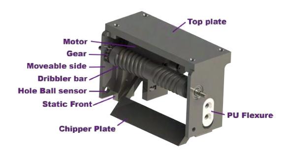
Figure 8 represents the new front assembly. It can be seen that it makes use of the two flexures to create the 2 DOF damping mechanism. Also, a chipper plate is there to create the third point of contact. Furthermore, it has a dribbler bar to apply backspin to the ball.
The flexures and dribbler are moulded from polyurethane (PU) rubber using custom-made ABS moulds. These moulds are FDM printed with a layer height of 0.08 mm using a 0.4 mm nozzle, to make sure the details and the surface finish are sufficient. The flexures make sure the front assembly can move both horizontally and vertically, which is needed because the impact of the ball when receiving is not perfectly horizontal. The working principle is that the PU flexure can deform, allowing some rotation of the dribbler bar around it, which can be seen as damping for the horizontal direction. Additionally, the assembly can slide in the vertical direction around the PU flexure because of a slot. The PU flexure is supposed to provide friction, damping this vertical direction as well.
As RTT's last ETDP [2] stated, the chipper plate is used to add a third point of contact with the ball, together with the ground and the dribbler bar. This was inspired by the ETDP of ZJUNlict [4], which improves ball-handling skills compared to a two-point contact model. After the RoboCup of 2023, it was concluded that the implementation of the chipper plate could be further improved for better usage of the third point contact. The new design of the chipper plate is inspired by the ETDP of ZJUNlict [4], the ETDP of TIGERs Mannheim[6] and the ETDP of RobôCIn[7]. The design focuses on getting the right tolerances, to ensure the ball has good contact with both the chipper bar and dribbler bar simultaneously.
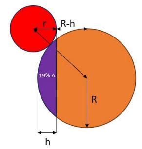
According to the rules of the SSL league, the ball should not be covered for more than 20%. The new front assembly is designed to have a maximum ball coverage of 19%. To make sure this is achieved, the height of the dribbler bar is calculated. Therefore, the ball coverage is calculated using:
$$A% \cdot \pi R^2 = R^2 \arccos(1 - \frac{h}{R}) - (R - h) \cdot \sqrt{R^2 - (R - h)^2}$$
The equation is derived from the circle segment formula [1]. The symbols of equation are represented graphically in Figure 9, whereas the red part is the dribbler bar, the orange part the ball and the purple the area that is covered by the robot. The R (mm) is the radius of the ball, r (mm) is the radius of the dribbler bar, h (mm) is the saggita [1], and A (mm²) is the covered area of the ball. Equation is solved numerically. The dribbler height is then calculated using Pythagoras. The resulting dribbler height is 43.625 mm measured from the ground.
The dribbler motor is rated at 10600 rpm, of which the specific model can be seen in table 1. To transfer this power to the dribbler bar, gears are used. With the robot of 2023, the dribbler bar could rotate at 8244 rpm, with the used gear ratio. The new robot's dribbler bar will have the ability to rotate at 17666 rpm, with a gear ratio of 5:3. During a test, where the gears of the previous robot were swapped places, it was observed visually that increasing our dribbling speed instead of lowering helped in receiving the ball and moving the ball towards the centre. However, no experiment has been performed to quantify this.
To conclude, the new front assembly will make use of a 2 DOF damping mechanism to handle the impact of the ball. Furthermore, more focus is put on implementing the third contact point of the ball. Also, the ball coverage does not exceed the maximum 20% set by the SSL rules.
2.1.6 General Changes
To fit the new PCBs on the bottom assembly, the middle and top plates are redesigned. Mainly the screw holes are relocated in order to place the PCBs and holes are created to guide the wires of all the boards and motors. Also, a cover is added to shield the high-voltage capacitors to increase the safety of handling the robot by preventing the capacitors from being touched easily. The details of all the made changes, such as technical drawings, will be made available at the RTT wiki before the 2024 RoboCup.
2.1.7 Production Methods
Most of the parts of the robot are designed in-house, because commercially available products generally fail to meet our requirements. These parts are then produced by one of our partners or FDM printed in-house. All of our metal parts are produced by a single partner, where the parts are made using milling, turning, drilling and laser cutting. The solenoid plunger parts are ground to lower the friction while kicking and chipping. Other parts are produced by additive manufacturing. The wheels and the front assembly are produced via SLS printing by a partner. The solenoid core and the middle and top plate are produced using an FDM printer in-house. Furthermore, the solenoid is wound by one of our partners.
2.2 Electronics
This year a complete redesign of the electronic system is being undertaken. Not all changes are included in this section; the most important ones are discussed. This includes new motor driver connectors, isolated board design, boundary scanning (JTAG), debugging and a shared bus. v2023 hardware had challenges regarding reliability. This causes delays in design progression as time is spent making repairs. The repair process takes longer than necessary due to a lack of debugging functionality. This will be improved upon in the new designs. During the design process bottlenecks were encountered regarding hardware upgrades. Certain hardware components were dependent on each other. Hence, this year it is decided to create upgradable hardware. This could be in the form of additional hardware or a redesign of any current hardware. Regardless of the desired change, this can be done without having to completely redesign the entire system.
2.2.1 New Motor Driver Connectors
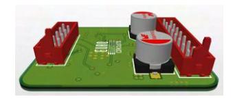
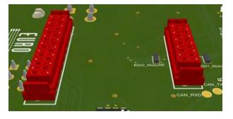
The motor driver connector will be replaced by two two-row connectors. The motor driver connector sockets are now placed on the top side of the motherboard as opposed to the sides. This way, the motor driver will be fully supported; v2023 had sockets that left the motor drivers hanging free off of the side of the motherboard. The connectors also have a larger number of pins making the connection between the head and socket stronger.
The cables required for the motor driver will now be connected to the motherboard rather than the motor driver itself. This acts to reduce the potential force acting on the motor driver board. The movement of the motor driver relative to the motherboard is now almost completely restricted. Additional screws could also be used in the future to restrict this movement completely. A concept render is shown in Figure 10.
2.2.2 Isolated Board Design
All boards have been redesigned with their own Micro Controller Unit (MCU). Each board can then communicate via a Controller Area Network (CAN) bus with the motherboard. The boards can operate in isolation, thus, the system is now truly modular. This in turn improves reliability as malfunctions are contained in isolated areas and cannot damage other parts of the system. Debugging functionalities can now be used to detect from which sub-systems an error has occurred — maintenance is more straightforward. An additional benefit is the freedom of redesigning each board independently as now no parts of the system are dependent on another sub-system.
2.2.3 Boundary Scanning (JTAG)
Soldering errors when prototyping and invisible, in-package chip malfunctions can put a halt to design progression and waste important time during match preparation. To ensure that these problems are easily alleviated a new technology has been employed on the boards. JTAG (Joint Test Acces Group) allows for boundary scanning. This is a process that uses features already present in most chips (in the case of RTT's hardware all MCUs have JTAG capabilities) to send and receive test signals along all traces to determine continuity. A software interface then allows for easy identification of any present continuity errors [9].
The addition of JTAG also yields another improvement: a better programmer connection. Currently, a custom connector allowing for programming and serial readout is used. his has been replaced by the standard JTAG connection, which not only retains all the previous functionalities but also has additional features. This has the advantage of improving hardware usability.
2.2.4 Debugging
Debugging functionality on the current hardware is scarce. It is also of little help when trying to diagnose precise hardware malfunctions. For these reasons, additional debugging functionality has been included.
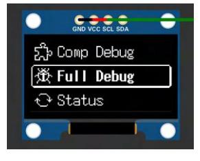
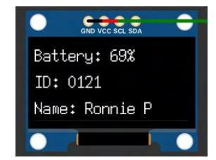
An OLED display has been implemented atop the motherboard; a menu that allows for debugging is displayed. The user interface for this is a combination of buttons and dip switches. The menu allows for precise detection and testing of hardware components without the necessity of a computer and time to prepare diagnostic programs. The menu can also display diagnostic information (ID, battery level, role etc.), allow for control parameter changes, display software debugging variables and more. It allows for much more extensive debugging functionalities to be available on the robots themselves instead of the old probe and schematic method. Figure 11 contains a concept render of the OLED display.
Additional test points have also been placed on the PCBs. These are placed in the areas following a likely malfunctioning area. This is commonly at IC outputs or high voltage/current handling components. The test points will allow for a quick diagnosis with a multi-meter to test basic functionality.
2.2.5 Shared Bus
To fix the upgradability problem, it was decided to connect all the boards using the CAN bus. Not only does this allow for upgradability, but the modular system design is also realised in this fashion. CAN is a serial, slaveless communication protocol. It has the benefit of being resistant to noise and interference; a differential signal pair cancels out common-mode signals along the wires. This is crucial as noisy signals can lead to system malfunctions. The robot will not perform optimally in this case as actuation signals could be corrupted by noise and, therefore, not have their intended effect (for example). Each board can now send and receive information via their MCU. A priority system can be implemented to determine which signals are communicated first to avoid collisions [3].
Each board can now work in isolation, making control over the robot's components more direct and local. This should improve the response time of our robot as any delays introduced by parasitic effect are removed (due to signals having to travel larger than necessary distances). The shared bus only uses two pins for communication, thus, the connector has been designed to include a power trace. This will directly supply the CAN transceiver chip, keeping the system compact and robust (a CAN connection does need an extra 5V supply from the board it is placed on). Upgradability is now possible; new boards require only a CAN connector (and relevant traces to its MCU) to be integrated with the system.
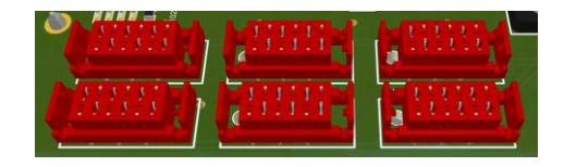
The new motherboard has six available CAN ports as shown in Figure 12. Two such connectors will be in use with current hardware — an extra CAN connector is used specifically for power board connectivity. This allows for the addition of up to four extra boards. This seemed sufficient as there was limited space within the robot body. An adapter board with extra CAN ports could be implemented if this proves too few. As mentioned this is unlikely unless hardware is reduced in size significantly.
2.2.6 New Motherboard
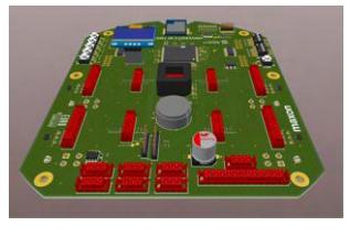
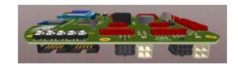
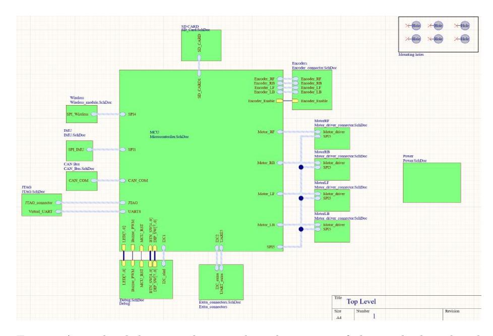
This is the central module of the system. The main processor, wireless communication and Inertial Measurement Unit (IMU) are all located here. The motherboard collects all data from the system sensors and relays this to the controlling algorithm via the wireless communication module. Any received instructions are also actuated via the motherboard. There are many differences between the old and new renditions. Figure 13 depicts a 3D model of the new motherboard from different perspectives. A top-level diagram of the motherboard showing its sub-systems and their interconnections is given in Figure 14.
One evident change is the board shape. The curvature and dimensions are similar to the previous edition as the robot's dimensions have not been altered. The cut-outs to fit the motor drivers present in the old design have been filled — the new motor drivers have been mounted to the motherboard's surface to improve connection security. Noticeable, is the cut-out beneath the antennae of the wireless chip. This allows the antenna to radiate in a full (as opposed to half) plane space as there is no (potential) termination of the electric field due to the PCB being directly below it. This is of course non-ideal as unobstructed emission is desired for better transmission efficiency[8].
The I2C pins were previously used for a UART interface for serial feedback from the MCU. These have been repurposed to allow for connection with other peripheral devices: a speaker for example. Furthermore, the motor driver connection was changed from the side to a top mount configuration — connection to the motor itself was added to the underside of the motherboard as opposed to the motor driver itself.
2.2.7 New Power Board
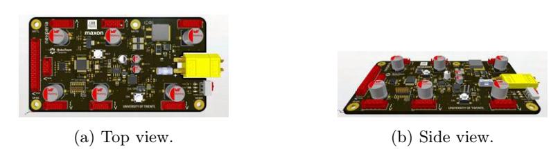
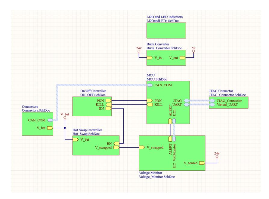
The power board acts as the power distribution centre. Connection of the supply battery to the system takes place here. Extensive changes have been made to the v2023 power board. In Figure 15 a 3D model of the new power board is shown. The top-level diagram of the power board's sub-systems and their interconnections is displayed in Figure 16.
The power board is populated with more components than the previous edition. An MCU present on the board allows for the mentioned isolated board design concept to be realised. Control and processing of the onboard ICs and sensors is managed by this MCU. This in turn communicates with the central MCU via the CAN bus to send or receive instructions or diagnostic information. Thus, the modular design of the system is actualised using this design method.
The board itself has another functionality: protection of the board from supply fluctuations. Therefore, chips (a hot swap converter) are put in place to protect against over-current and reverse polarity. This onboard MCU is now directly connected to the powerboard's MCU ensuring that any potential supply malfunctions will have effects isolated only to the power distribution part of the system.
The additional power connectors are to allow for the connection of new hardware; this matches the number of CAN connectors. A separate motherboard power connection is also present. To improve system modularity the Buck (DC-DC) converter is now placed on the power board. The voltage it converts (24V−5V) is required on the motherboard (the motherboard, in turn, distributes this 5V to other boards via the CAN connection) and is more logically placed on the power board as it tends more to its function in the entire system (power handling). The Buck converter is also subject to regular malfunction. It is, therefore, better placed on a different board to isolate the issue to a smaller, more easily replaceable (the motherboard contains a larger number of and more expensive components) part of the system.
References
- Circular segment - wikipedia, https://en.wikipedia.org/wiki/Circular_segment
- Andringa, J., Bink, T., Bojkow, B., Bojorge-Alvarez, J., Born, H.V.D., Doornkamp, C., Ganzeboom, E., Javed, U., Meulenkamp, T., Steerneman, E.: Roboteam twente extended team description paper for robocup 2023 (2023), https://roboteamtwente.nl
- Circuits, A.A.: Introduction to CAN. https://www.allaboutcircuits.com/technical-articles/introduction-to-can-controller-area-network/ (2019)
- Huang, Z., Chen, L., Li, J., Wang, Y., Chen, Z., Wen, L., Gu, J., Hu, P., Xiong, R.: Zjunlict extended team description paper for robocup 2019 (2019). https://doi.org/10.48550/ARXIV.1905.09157, https://arxiv.org/abs/1905.09157
- Monat, C., Dankers, E., Skurule, K., Steenmeijer, L., Sijtsma, S., Diamantopoulos, S., Aggarwal, R., Smit, T., van Harten, A.: Roboteam twente extended team description paper for robocup 2022 (2022), https://ssl.robocup.org/wp-content/uploads/2022/04/2022_ETDP_RoboTeam-Twente.pdf
- Ryll, A., Jut, S.: Extended team description for robocup 2020 (2020), https://tigers-mannheim.de
- Silva, C., Alves, C., Silva, E., Martins, F., Cavalcanti, L., Maciel, L., Vinícius, M., Monteiro, J.G., Moura, P., Cruz, J.V., Santana, P.H., Sousa, R., Rodrigues, R., Fernandes, R., Morais, R., Araújo, V., Silva, W., Barros, E.: Robôcin extended team description paper for robocup 2022 (2022), https://robocin.com.br/
- Solutions, C.P.: Antenna Design Principles for PCB Designers. https://resources.pcb.cadence.com/blog/antenna-design-principles-for-pcb-designers (2021)
- Technologies, J.: Boundary Scanning. https://www.jtag.com/boundary-scan/ (1993)
- Yang, T., Chen, Q., Feng, Y., Hai, Y., Du, F.: Experimental validation and numerical simulation of flexible and microscale roll gap control technology. The International Journal of Advanced Manufacturing Technology 120, 5741–5754 (2022). https://doi.org/10.1007/s00170-022-09000-x, https://doi.org/10.1007/s00170-022-09000-x