SRC Extended Team Description Paper for RoboCup 2024
Ziming Chen, Shaoming Pan, Yuquan Wang, Liangcheng Jiang, Yun Bao, Juntong Peng, Yuhong Tan, Xiaoxiao Zhu
Student Innovation Center, Shanghai Jiao Tong University, P.R.China
Abstract This paper introduces the achievements which the SRC Team made in the last year. In the software part, we achieve adaptive supporting point calculation, ball prediction and simulation of visual blind zones. In the electronics part, an automatic motion calibration method is introduced. In the mechanics part, we imporve the center of gravity and the roller. We hope to do well in RoboCup 2024 based on these achievements.
Introduction
We are the SRC Team of Shanghai Jiao Tong University. We had our first small-size league competition in 2017. Since then, we have been locating problems and discussing where we can improve. Last year, we proposed an adaptive method based on supporting point calculation. In order to improve the quality of passing and intercepting, we introduced a ball prediction method. In the electronics, we proposed an automatic motion calibration method and an embedded improvement for existing circuit diagrams. In the mechanics, we enhanced the center of gravity and experimented with new roller designs. Lastly, we made certain modifications to grsim to simulate the visual blind zones.
Software
2.1 Adaptive Supporting Point Calculation
In previous version, we computed the optimal point in each region and then employed a method of specifying passing areas for passing in practical applications. However, this approach lacked intelligence since the designated area might not necessarily contain the optimal point in the current scenario. Therefore, we further optimized this algorithm to automatically select the optimal points within the divided multiple regions for passing.
However, in scenarios of fast and fierce confrontation, we encounter new challenges. Despite the algorithm's ability to automatically select the optimal passing points, it's difficult to execute single-pass actions in rapidly changing game situations. The designated points may undergo rapid changes, leading to unintended oscillations and prolonged possession of the ball, which may result in fouls or loss of the possession.
To address this problem, we devised an algorithm that sets a certain score threshold among the obtained multiple planned points. When the score reaches a certain proportion of the optimal point, it is stored in the pre-passing point queue. During the process of robot adjusting its posture to prepare for passing, if a passing point that can be immediately executed is encountered, it is promptly shot out. During our comprehensive experiments, this algorithm showed significantly enhanced passing efficiency and success rate compared with the original one.
In the last version of the region division, the boundaries of the regions were fixed and would not change as the field situation changes. We designed a new algorithm to dynamically adjust the region division based on the position of the ball. Basically, the calculation method linearly adjusts the position of each boundary of each region with the coordinates of the ball's position. During passing, the planned points can be closer to the ball without losing global awareness.
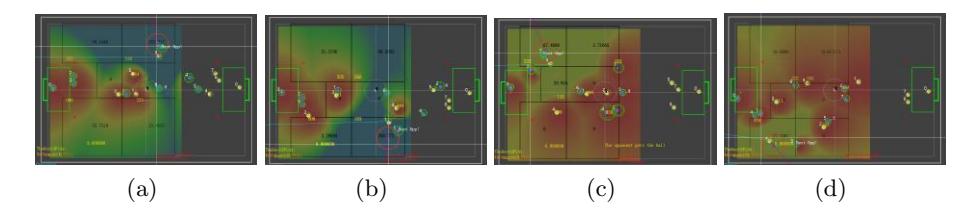
Specifically, during defensive counterattacks, the robots can quickly receive and pass the ball at near range under the interception of the opponent, while seizing the opportunity to pass out of the half-court. During offense, they can be closer to the opponent's half and creates more scoring opportunities without unnecessarily passing the ball back to their own half, thus posing a greater threat to the opponent. We have shown the actual effect of this fixation for offense in Figure 1.
This dynamic adjustment ensures adaptability to rapidly changing game situations and optimizes passing strategies accordingly, thereby enhancing the overall performance of the attacking strategy.
2.2 Ball Prediction
In order to improve success rate of passing, a predictive approach is employed to estimate the future position of the ball based on its current position and velocity.
Initially, the velocity values of the ball are collected and organized into matrices to facilitate processing by the graphical processing units (GPUs). During both the training and inference phases, a neural network model is trained using a loop that iterates over a predetermined number of epochs. By iterating through multiple epochs, there is the opportunity to escape local optima and move towards the global optimal solution, while overfitting may also be alleviated. We use mean squared error (MSE) as the loss in the model, which is determined by comparing the predicted output to the actual output data. MSE's quality of non-negativity, symmetry, and having only one unique minimum value makes it easier to find the minimum value of the loss function. Then, by obtaining the optimal matrix within the neural network, the anticipated position and velocity of the ball can be calculated in real-time using the data obtained from the camera during the match.
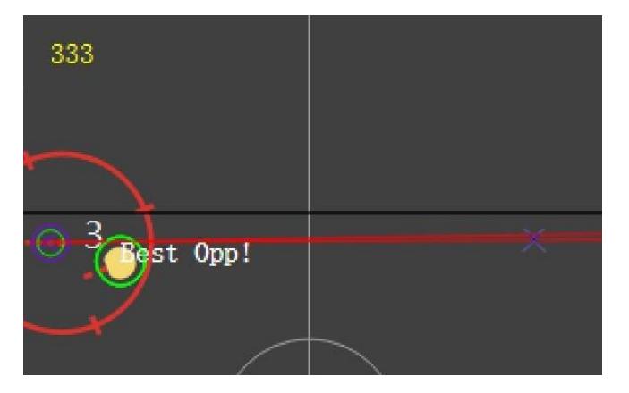
As shown in Figure 2, the point with a green circle and the purple circle around is the ball, and the purple X on the right is the position where the ball is supposed to stop at. The red line connecting the ball and the position is the direction of the ball.
2.3 Simulation of Visual Blind Zones
In real-world scenarios where lighting conditions or camera view are limited, visual blind zones on the field can occur due to potential obstructions to the camera's field of view by robots. This can often lead to missed offensive opportunities, as our robots' behaviors can become undefined or poorly tested when they lose sight of the ball. However, the simulator we are using now, the grSim generates vision packets by directly acquiring the ball's location, not through camera usage. This makes it challenging for us to enhance our system's robustness. To address this problem, we have investigated the mechanism of blind zones and incorporated it into grSim.
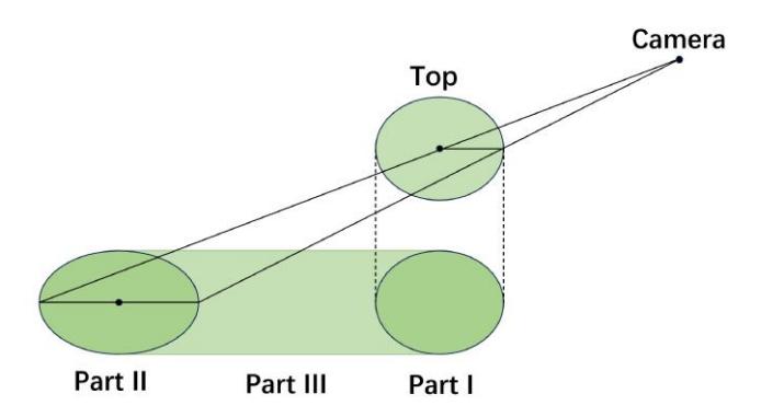
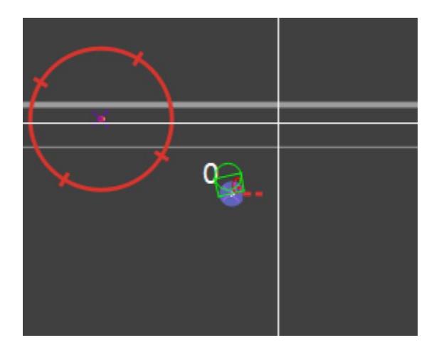
A camera's blind zone created by a single robot consists of three parts. The first part is the base of the robot, and the second part is the circular projection of the robot's top onto the ground. Within this projection, the relationships among the projection radius, the top radius, and the camera form a similar triangle, with their centroids aligning collinearly. These two circular components are connected by two external common tangent lines, constituting the third part of the blind zone. From this, we can easily calculate each robot's blind spot, as depicted in Figure 3 and simulated in Figure 4, where blind spots are represented by green lines.
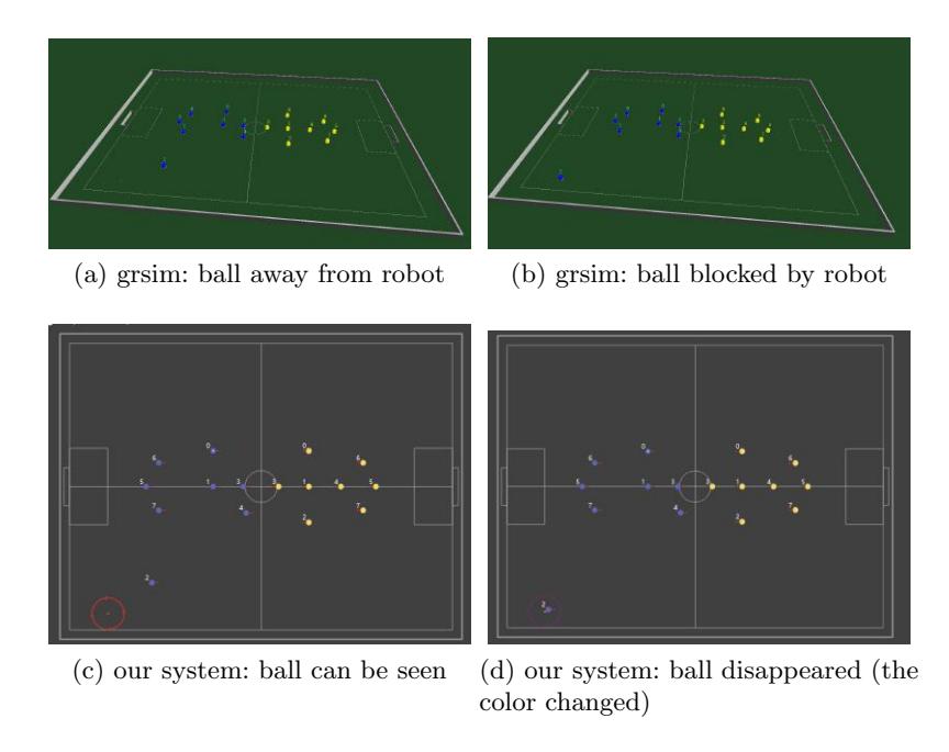
To incorporate the model into grSim, we maintain a list of blind zones for each camera. This list is cleared at the beginning of each vision packet generation and is subsequently appended as the camera checks every robot within its range. Finally, we ensure that information about the ball is added to the packet only if it is not within any of the blind zones. The effects are demonstrated in Figure 5.
In summary, the simulation of vision blind zones enhances the fidelity of our grSim environment. It allows us to better prepare our robots for general match fields, where vision obstructions are common. This improvement aids in the development of more robust strategies and behaviors, particularly when our vision system loses sight of the ball. As a result, we increase our chances of maintaining offensive opportunities and overall performance in actual games. We are also willing to contribute to the open-source community and have already created a pull request on the original repository.
Electronics
3.1 Introduction of existing design
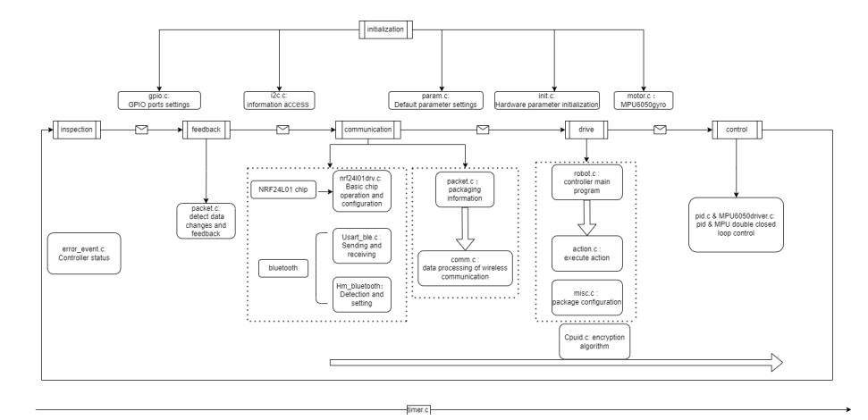
Our serving robots' electronics design has maintained its structure since 2017, which includes two circuit boards, a control board and a power board. The power board is responsible for distributing the electric energy of the battery to all parts of the robot, supplying power to the control board and driving the electromagnet to kick or chip the ball. The control board receives the control commands sent by the host computer. There are also motor control, wireless communication and sensor fusion modules on the circuit board. We use STM32F407VET6 as the main chip to coordinate the work of each module and deal with triggered events. The workflow of the embedded main program is shown in Figure 6.
The result of experiments conducted through 2023 and SRC's serving robots' performance in Robocup Chinaopen 2023 have exposed obvious shortcomings in our electronics design, evidented by the fact that the lack of communication capabilities and relatively low control rates. These have impaired the control and planning performance of the overall system in matches.
The existing robots have limited accuracy in open-loop motion, and rely heavily on algorithms in closed-loop control. The team's effort to correct the deviation of the speed direction of the vehicle by using feedback of gyroscopes was barricaded by excessive delay in system. As a result, the robots still rely on the PID control to stablize the wheel speed from deviation caused by mechanics and motor errors. We fine-tune the structure and parameters of PID algorithm before tests and matches to ensure the motion performance.
3.2 Automatic motion calibration
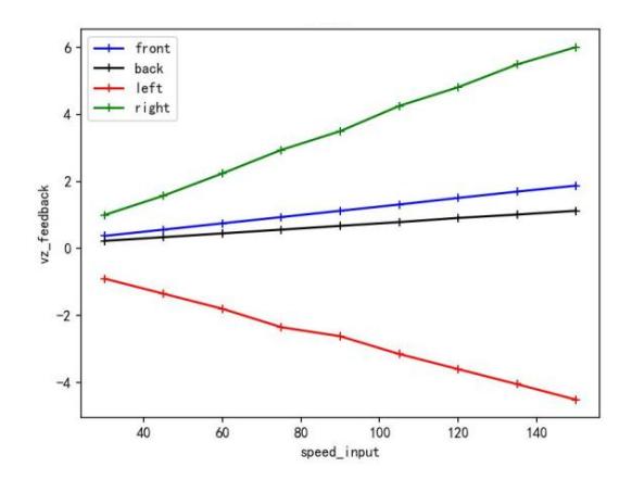
In 2023, to save time and automatically calibrate the motion performance, we have designed a new strategy for motion calibration. The strategy drives the vehicle to execute multiple motion commands in sequence and obtains the angular velocity measured by the gyroscope when the vehicle moves in different directions at different speeds. Since the given commands are all designed as linear motion, the expected angular velocity is zero, and the actual speed output of gyroscope is the motion error.
While handling the data received from robots, we preprocess the data according to temporal cross-correlation eliminating, the error caused by communication lags. A fitting of the motion error and the magnitude of the velocity is implemented then to calibrate the relevant parameters related to the errors in different directions.
After calibration, by applying an angular velocity in the opposite direction, the motion error can be eliminated from the root and the delay of motion adjustment can be reduced.
3.3 Upcoming update of embedded system and circuits design
To catch up with the most competitive teams in Robocup SSL, our team has started to develop a new architecture of embedded systems since August 2023, with the goal of utilizing Wi-Fi communication and Field Oriented Control to improve the overall performance of robots.
Our project updates the main control chip from STM32F407 to Raspberry Pi 4, which has solid computing resources and diverse interfaces for further extensions. The Raspberry Pi takes the duty to receive commands from host computer, send control commands to control board, and retrieve feedback of sensors. In 2023, We've implemented and tested the initializing and Wi-Fi & I2C communication functions on Rasp Pi. The introduction of Wi-Fi protocol has been proven to greatly enhance the communication speed and bandwidth between the robots and the host computer, which can effectively suppress the lags in signal transition and improve control rate.
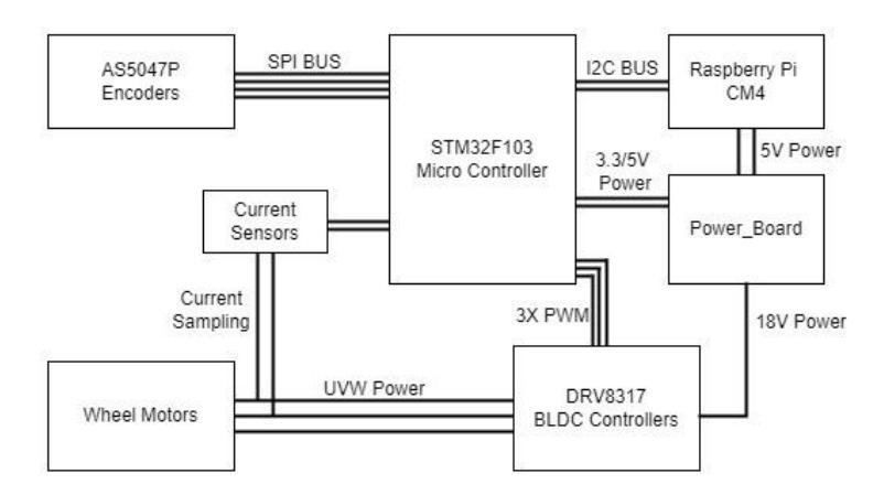
Field Oriented Control (FOC) is a well-known strategy for controlling brushless direct current motors (BLDC). By using FOC, BLDC in wheeled mobile robots can be accurately controlled and achieve better reversing performance, ensuring the smoothness of forward and reverse switching even when running at high speed. The control board of robot is revised to apply the FOC method in motion control, using a STM32F103 as microcontroller and DRV8317 as FOC driver chip with current loop. The structure of FOC-applied control board design is shown in Figure 8. We are now validating the PCB design of new control board and plan to update all serving robots in 2024.
Mechanics
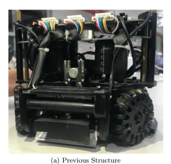
The general design and architecture of the robots have been freezed since 2017, as shown in Figure 9a, however, we have been continously modifying the design based on competition experiences and insight from top teams' opensources materials.
4.1 Center of Gravity Improvements
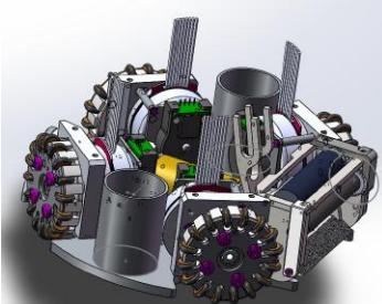
The first noteworthy adjustment involves the power board capacitors. We reduced the number of capacitors from four to two and strategically moved them to the lower part of the base plate. This shift indends to lower the center of gravity, as shown in Figure 9b.
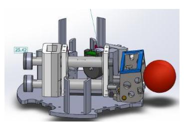
However, the initial improvements did not meet our performance expectations. We then combined the kicker and chipper on the center plate with a flat shooting shovel on the base plate, as shown in Figure 9c.
This integrated structure further lowers the center of gravity, aligning more closely with our performance objectives. Although this redesigned model has been completed, it has not yet been tested in competition due to time constraints. We are in the process of testing and optimization, hoping to deploy this improved model at the upcoming global competition, where it is expected to demonstrate enhanced stability and agility.
4.2 Roller Modifications
Our initial mouth roller design, unchanged for years, was reconsidered after observing the superior ball-handling capabilities of competitors' robots with varied roller shapes. This realization prompted us to innovate our roller's shape and material to enhance ball intake efficiency.
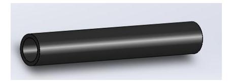
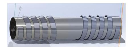
Shape: The new roller features a hollow cylindrical body with an outer diameter of 10mm and a length of 65mm, with a wall thickness of 2mm. Its surface is adorned with a helical wedge-shaped spiral, with the spiral's maximum cross-sectional width being 0.5mm.
Material: Utilizing 3D-printed soft rubber with a Shore hardness of 60 which is identified as optimal through extensive hardness testing, and a sandblasted aluminum alloy for the central cylindrical core, we aimed for a balance of flexibility and durability.
Performance Test: The modified roller achieved a maximum stationary rotation speed of over 400 rpm. However, it exhibited shortcomings in sustained adhesion, suggesting room for improvement.
We are hopeful that by further improving material selection, adjusting the feed angle and increasing motor power, we can achieve better results. While our improvements have yielded promising results, we recognize that optimization continues. The original roller is shown in Figure 10. The new roller is shown in Figure 11.
Conclusion
In the previous sections, we introduced our development efforts from the software, electronic and mechanics sections respectively. In the software section, We introduced our new adaptive supporting point calculation method, ball prediction method and simulation of visual blind zones. In the electronics section, we introduced an automatic motion calibration method and our upcoming update of embedded system and circuits design. As for the mechanics, we improve our roller and adjust the center of gravity. We expect our robots to have better performance in Netherland.
References
- Zhao, Yue, et al.: ZJUNlict: RoboCup 2013 small size league champion. Robot Soccer World Cup. Springer, Berlin, Heidelberg, 2013.
- Munkres J . Algorithms for the assignment and transportation problems[J]. SIAM. J, 1962, 10.
- Juan Pablo Mendoza, Joydeep Biswas, Danny Zhu, Philip Cooksey, Richard Wang, Steven Klee, Manuela Veloso.: Selectively Reactive Coordination for a Team of Robot Soccer Champions. In:Proceedings of AAAI'16, the Thirtieth AAAI Conference on Artificial Intelligence, Phoenix, pp.3354-336
- Skuric, Antun, et al. "SimpleFOC: A Field Oriented Control (FOC) Library for Controlling Brushless Direct Current (BLDC) and Stepper Motors." Journal of Open Source Software 7.74 (2022): 4232.
- Zheyuan Huang, Haodong Zhang, Dashun Guo, Shenhan Jia, Xianze Fang, Zexi Chen, Yunkai Wang, Peng Hu, Licheng Wen, Lingyun Chen, Zhengxi Li, and Rong Xiong, ZJUNlict Extended Team Description Paper for Robocup 2020.(2020)
- Jiawei Lin, Jie Chen, Baiji Chen, Kaichong Lei, Zikang shi, Jiaping He, Zhengwei Qin, Jiaxuan Xie, Jingwei Xu, Zhaocong Liu, Ruiqing Ge and Li Hao, SRC Team Description Paper for RoboCup 2020. In RoboCup 2020 (2020)
- Monajjemi, Valiallah, Ali Koochakzadeh, and Saeed Shiry Ghidary. "grsim–robocup small size robot soccer simulator." Robot Soccer World Cup. Springer, Berlin, Heidelberg, 2011.