Sysmic Robotics Team Description Paper 2024
Aaron Arriagada, Nelson Cortés, Ignacio Jiménez, Gerson Marihuan, Daniela Moya, Irina Richards, Claudio Tapia, Cristóbal Valenzuela
Universidad Técnica Federico Santa María
Abstract This paper briefly describes what the team has developed for the fourth generation of robots, in particular by mentioning the changes that have been made since the last participation at the 2023 RoboCup in Bourdeaux, France. The team's approach this year was to optimize the kicker system, restructure the design of the robot's prototype, integrate a new ball proximity sensor, the creation of a new client and finally, a new version of the data package sent to each robot. The topics involving the work, such as electrical, mechanics, software and firmware, were designed according to satisfy the Robocup rules.
Introduction
Sysmic Robotic, is a team of engineering students from the Technical University Federico Santa Maria. The team first attended the Small Size League (SSL) in 2018 in Montreal under the name "AIS", participating in Division B. In 2023, the team had the opportunity to join the RoboCup held in Bordeaux, gaining valuable experience and more importantly, feedback.
Section 2 presents a brief overview of the mechanical robot's design, including all the small modifications that have been made to the drive train, dribbler, kicker and the case.
Section 3 describes in detail the changes made to the hardware of the robots. Adding a new kicking system, allows to charge the associated capacitors 6 times faster than previous designs. Additionally, modifications were made to the main board, improving the last version built in 2019, aiming to reduce the noise in the signals that pass through it. Furthermore, good practices gathered from experience were implemented within the new version of the main board.
Section 4 addresses the changes made in the software area, presenting the current development of a new graphical user interface (GUI) for the team's client, as well as modifications in the communication packages between it and the robots. These improvements reflect a comprehensive effort to enhance the performance and functionality of the robots across various domains.
Mechanics
Summary of structural design
The current version of the robot generally has the same structure as the design submitted in the RoboCup 2023 application. The main features of the mechanical design are:
- Structure composed of parts printed in PLA filament joined by two 3 [mm] thick mdf discs.
- Height of 13.5 [cm] and a diameter of 18 [cm].
- Upper case made of lightweight material, currently cardboard and PLA filament
- The external part of the wheels are 3D printed.
By 2024, changes were made to improve the robot's performance.
Dribbler
The dribbler, which in its previous version was made of moldable silicone, is now manufactured by 3D printing using Thermoplastic polyurethane (TPU) filament. This allows for a more balanced design and greater control over the ball when maneuvering.
Kicker
The current advancement involves the integration of a double kicker into the robot, enabling it to execute passes and, with the inclusion of a shift-kicker, play at varying heights. This expansion broadens the repertoire of plays available to robots during gameplay. This feature has been designed, manufactured and used by different teams in the RoboCup, we were specifically inspired by RoboFEI's 2010 TDP and ZJUNlict's 2012 and 2016 ETDP.
Drivetrain
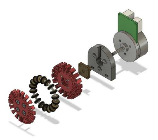
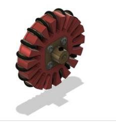
The modified bolt coupling from the previous TDP was eliminated and replaced with a commercial flange type coupling, which is anchored to the wheel with four countersunk hex bolts and attached to the motor shaft with a precision hex bolt. This allowed to reduce fabrication, assembly and repair times. This assembly can be seen in Fig. 1 and Fig. 2 shows a better view of the connection between the wheel and the coupling.
Case
Historically, the upper case has been made entirely of cardboard. For this version, it has been decided to manufacture the lid with PLA filament in order to have a more solid version that will also include pockets to place the robot's IDs, without damaging them. By maintaining its core design principles, the edges will continue to be crafted from cardboard, preserving the elasticity it offers.
Hardware
This year, hardware modifications primarily focused on the development of the kicking board, which underwent exhaustive testing to finalize its implementation, as outlined in the 2023 TDP. Additionally, adjustments were made to the main robot board aimed at reducing noise, temperature of certain components and more aesthetic aspects of the board.
As for the firmware, a sensor was integrated to detect the ball. This information allows the robot to determine when it is in possession of the ball and thus be able to act accordingly. These changes and revisions will be detailed below.
Kicker
Manufacturing of the kicking boards has achieved functional status, achieving capacitor charging in approximately 4 seconds. This design has been replicated for all robots. One notable aspect of the kicking board designed for use with the LT3751 integrated circuit is the inclusion of a section for measuring the capacitor charging voltage. When implemented in conjunction with the bleeder resistor, this feature would allow for control of the robot's kicking intensity, adding another level of control towards the ball. Currently, efforts are underway to test and implement this feature in the hardware, followed by the development of associated firmware for kicking intensity control. Additionally, integration within the software is planned so that the robots' AI can send the desired kicking intensity level.
Furthermore, the kicking control circuit included flags for "Done" and "Fault", indicating when the capacitors reach the desired voltage and when an error occurs during the capacitor charging process, respectively. Despite testing, these signals did not function as expected. The "Done" flag would activate as soon as the capacitors acquired even a low voltage instead of triggering when they reached the desired voltage. Conversely, the "Fault" flag would randomly activate.
Ideas for Future Development for Kicker Board (2024 and Beyond):
- Investigate alternative methods for capacitor charging control to ensure accurate and reliable activation of the "Done" flag upon reaching the desired voltage level, maybe making use of the measuring of the current capacitor voltage level.
- Explore the LT3751 IC to accurately identify and address issues leading to the random activation of the "Fault" flag.
- Optimizing the space usage of the kicker board once its functionality has been ensured.
- Develop a switching system to enable the utilization of two solenoid kicker systems, providing the capability to execute two different types of kicks.
Integration of Firmware and Software:
- Develop firmware to support the implementation of kicking intensity control, ensuring seamless integration with the hardware components.
- Integrate the kicking intensity control functionality within the software framework to enable communication with the robot's AI for dynamic adjustment of kicking parameters during gameplay.
Continuous Testing and Optimization:
- Conduct rigorous testing and optimization of the kicking control system to fine-tune performance and address any remaining issues with flag activation and capacitor charging reliability.
- Collaborate with software and AI teams to ensure alignment between hardware capabilities and software requirements for effective gameplay strategies.
Main board
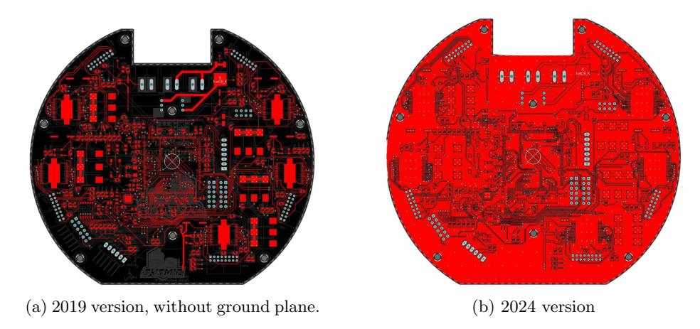
The main board has undergone certain modifications since the last version, which was published in the 2019 TDP. These modifications are focused on reducing noise, temperature in the motor controllers, and also on other best practices implemented, such as correcting tracks and traces.
The main changes for reducing noise and temperature are as follows;
- Creation of two ground planes, both on the bottom layer and on the top layer.
- Adding more ground vias in different areas of the board, especially in zones where the ground was far away from the components.
- The contact surface area of the drivers conductors was expanded, providing them with a larger ground plane, with the intention of reducing temperature, especially during periods when the driver handles large currents.
On Fig. 3, one can appreciate a view of the top layer of the main board of the 2019 version and also a top view of the top layer of the main board of the new version.
In addition to the previously mentioned changes, other relevant modifications were implemented to optimize the mainboard's performance. Correcting the position of certain components was aimed at optimizing spatial utilization and enhancing overall efficiency. Furthermore, adjustments to traces and tracks on the board were made to ensure optimal signal integrity and reliability, contributing to the board's enhanced functionality and performance.
Ideas for Future Development for Main Board (2024 and Beyond):
- Re-design and modularize the mainboard to facilitate a more sustainable approach to developing and testing robot features without jeopardizing the entire board. Currently, the team faces challenges when a single section of the board fails, resulting in the entire robot being compromised.
- Incorporate a battery voltage indicator and alarm directly into the board, eliminating the need for an external component attached to the robot's chassis.
Proximity Sensor Integration
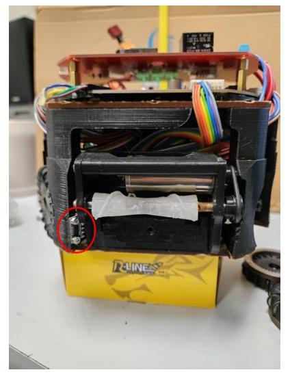
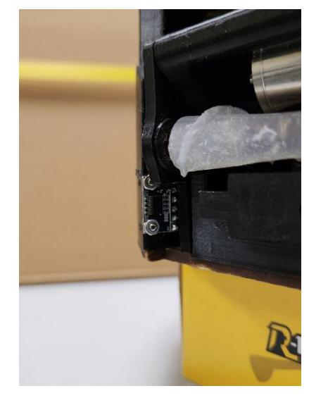
The hardware evolution introduces a pivotal upgrade – the integration of a proximity sensor strategically positioned beneath the dribbler and attached to one side of our main front pillar as seen in Fig. 4a. This sensor delivers realtime, accurate readings of the ball's location, significantly influencing intelligent decision-making during gameplay. It defines a threshold; if the ball's proximity is outside this range, the kicker will not execute a kick.
The primary enhancements resulting from this upgrade include:
– Precise measurement of ball proximity. Firmware intervenes to block kicking if the ball is beyond the defined threshold, optimizing overall performance.
Software
Custom client
In the past years, the team relied on a fork of the RoboJackets open-source software client to participate in the competition, and to test the mechanic's capabilities and hardware functionality of our robots. Due to the increase in the number of team members studying computer science, the opportunity was seen to be able to further develop software more suited to our needs with a client that matched the characteristics of our robots. Currently, a new version has been developed based on an unfinished project created by former members of our team. The current objective is focused on creating a base framework that allows easy incorporation of future high-level research, thus creating a testing ground for old and new members.
New version of the data package
To improve the resolution of the speeds delivered to each robot, the size of the data packet based on the work of ZJUNlict has been increased by one byte. This enables to deliver significant bits that allow better speed control. The contents of this package are shown in Table 1.
The first byte of the forward packet contains 8 bits. Bit 0 (callback or CB) indicates whether the robot should send a feedback packet back to the client; it is set to 1 to instruct the robot to send packets, and 0 to indicate that it should not send feedback packets. Bit 1 indicates whether the robot should kick the ball; it is set to 1 to instruct the robot to kick, and 0 to indicate that it should not kick. Bits 2 to 4 indicate the dribbler strength, and bits 5 to 7 indicate the robot ID to which the instruction is sent. Bytes 1, 2 and 3 then correspond to the sign and the 6 least significant bits of the $v_x$, $v_y$ and $v_\theta$ components of the velocity vector command sent to the robot. Byte 4 contains the 3 most significant bits for $v_x$ and $v_y$ and the 2 most significant bits for $v_\theta$, where experience has shown that no extra resolution is required.
Currently, a feedback package is under develop to transmit information from the robots to the client side (see Table 2). Although this package is still in the early stages of development, it already includes data on the dribbler velocity, kicker activation, ball possession, and wheel speed. In addition, the robots are also sending data on local accelerations and yaw angular velocity measured by an integrated inertial measurement unit. This data is intended for use in data logging and an upcoming local position estimation method that will give the robots greater autonomy.
Table 1: Forward communication protocol
| bit/byte | 7 | 6 | 5 | 4 | 3 | 2 | 1 | 0 |
|---|---|---|---|---|---|---|---|---|
| 0 | Robot ID | Dribbler strength | 1: Shot | CB | ||||
| 1 | ± | Speed vx | ||||||
| 2 | ± | Speed vy | ||||||
| 3 | ± | Speed vθ | ||||||
| 4 | Sig. bits vx | Sig. bits vy | Sig. bits vθ |
Table 2: Feedback communication protocol
| bit/byte | 7 | 6 | 5 | 4 | 3 | 2 | 1 | 0 |
|---|---|---|---|---|---|---|---|---|
| 0 | Robot ID | Dribbler strength, Shot | ||||||
| 1 | ± | Wheel speed φ0 | ||||||
| 2 | ± | Wheel speed φ1 | ||||||
| 3 | ± | Wheel speed φ2 | ||||||
| 4 | ± | Wheel speed φ3 | ||||||
| 5 | ± | Front acceleration ax | ||||||
| 6 | ± | Side acceleration ay | ||||||
| 7 | ± | Yaw angular velocity θz | ||||||
| 5 | Sig. bits ax | Sig. bits ay | Sig. bits θz |
Graphical Interface
At the outset of developing the new code, the team encountered a challenge with testing and debugging path planning algorithms due to the absence of a visualization tool for the generated routes and robot tracking. To address this issue, a graphical interface was coded in C++ to ensure rapid response times and provide specific solutions:
- Path Visualization: The interface provides a graphical representation of the planned routes for the robots. This allows the team to visually observe the routes generated by the planning algorithms, identify potential issues, and make adjustments as needed.
- Game Visualization: Real-time visualization of the game scenario allows users to monitor the positions and actions of all participating robots. Key game events such as ball possession, goals scored, and robot movements are dynamically depicted, offering valuable insights into the ongoing gameplay.
- Robot Command Transmission: The interface facilitates seamless transmission of manual commands to individual robots, enabling precise control over their movements and actions. This functionality is particularly beneficial for testing new strategies, plays, and skills, such as directing robots to move to specific positions or shoot at specifics targets.
References
- Georgia Tech RoboJackets software for the RoboCup Small Size League (SSL), https://github.com/RoboJackets/robocup-software
- Huang, Z., Chen, L., Li, J., Wang, Y., Chen, Z., Wen, L., Gu, J., Hu, P., Xiong, R.: ZJUNlict Extended Team Description Paper for RoboCup 2019. CoRR abs/1905.09157 (2019), http://arxiv.org/abs/1905.09157
- Jin, L., Chen, L., Chen, X., Li, Y., Hu, W., Xiong, R.: ZJUNlict Extended Team Description Paper for RoboCup 2016 (2016)
- Jr, J.A.G., Nascimientos, E., Malheiro, D., Zanatto, F., Francischini, G., A.Pereira, L.R., Cortez, M., Tebet, B., MArtinez, S., Bianchi, R.A.C., Tonidandel, F.: RoboFEI 2010 Team Description Paper (2010)
- Rodenas, T., Alfaro, R., Reyes, P., Pinto, F., Aubel, M., Hernández, N., Yáñez, P., Barrera, T., Torres, D., Alvarez, J., Quiroz, D., González., R.: Sysmic Robotics - Team Description Paper (2019)
- Rodenas, T., Torres, D., Reyes, P., Peña, J., Tapia, C., Moya, D.: Sysmic Robotics - Team Description Paper (2023)
- Wu, Y., Yin, P., Zhao, Y., Mao, Y., Wang, Q., Xiong, R.: ZJUNlict Extended TDP for RoboCup 2012 (2012)