The A-Team Team Description Paper 2024
C. Avidano, M. Barulic, C. Clark, R. Osawa, J. Spall IV, W. Stuckey, M. Woodward
The A-Team
Abstract "The A-Team" is a community team from the United States participating in our second year of RoboCup SSL. Our mission is to practice technical skills, inspire the communities in which we are present, and stay connected with friends across the globe. This paper presents the work done since the 2023 TDP. Focus is placed on the development of our first competition-ready platform, ongoing improvements to platform and software since the 2023 Bordeaux event, and exploratory work experimenting with novel approaches to SSL challenges.
1st Generation Platform
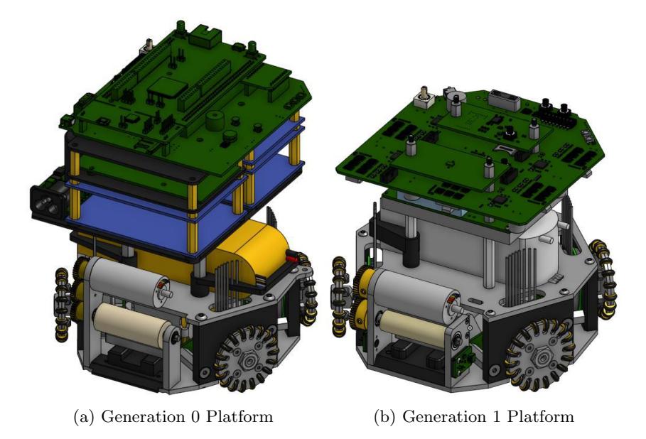
The team was in a unique position for 2023 qualification; the qualification robot was designed and built in 8 weeks from December 7th to January 31st due to severe supply chain supply shortages on micro-controllers, motor controllers, and radios. These parts suddenly became available, so the team purchased parts stock and development boards with the hope of qualifying. The qualifying robot only met the radial dimension requirement of 180mm, and was over 200mm tall. This is Generation 0. The rules compliant robot, dubbed Generation 1, was designed in the 5 months prior to competition.
Robot Generations
| Name | Development | Use |
|---|---|---|
| Generation 0 | DEC 2022 - JAN 2023 | JAN 2023 |
| Generation 1 | FEB 2023 - DEC 2023 | FEB 2023 - Present |
| Generation 2 | OCT 2023 - Present | TBD |
Mechanical
The Generation 1 mechanical platform focused on the changes needed to be competition ready and rules compliant. While many small adjustments to the design were made, the largest improvements were made to the kicker and dribbler assemblies.
Dribbler Assembly
The Generation 1 dribbler assembly, shown in Figure 2, is more reliable than the previous generation and adds a break-beam sensor for detecting ball possession. A cross member was added for a more rigid frame. The rubber dribbler roller diameter was reduced to 13mm. This allowed us to remove the third idling gear and reduce the overall assembly size.
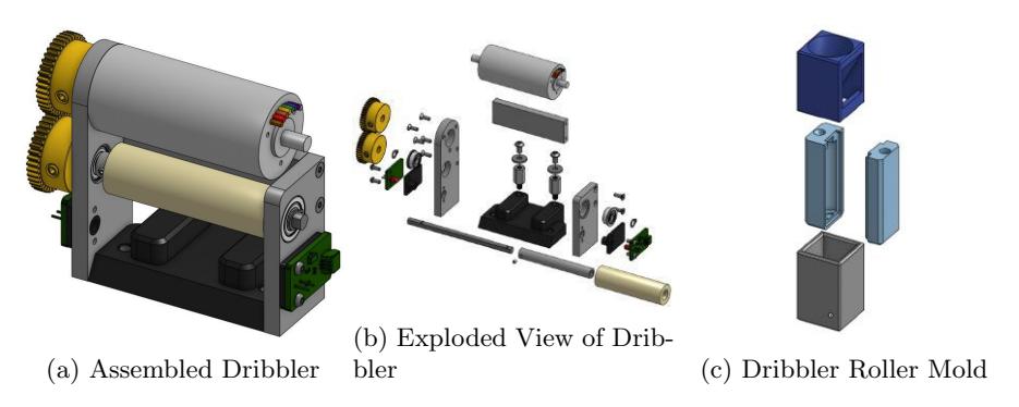
The break-beam sensor uses an infrared LED and a receiver to detect the presence of the ball. Each PCB is mounted on a black 3D printed mount which includes a shroud for the LED and receiver. This black shroud mitigates interference from ambient lighting.
The dribbler roller is still molded using Smooth-On Vytaflex 30 Urethane in a 3D printed mold. However, inspired by the mold design shown in Thunderbots' 2023 TDP, we changed from a mold held together by screws to one held together by an outer sleeve as seen in Figure 2c. This change and the addition of a funneling cap made our dribbler molding process dramatically easier and faster.
Kicker Assembly
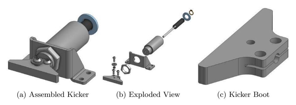
The Generation 1 kicker assembly, shown in Figure 3, is built around a smaller solenoid and attempts to fix weaknesses in the way the boot mounts to the solenoid plunger.
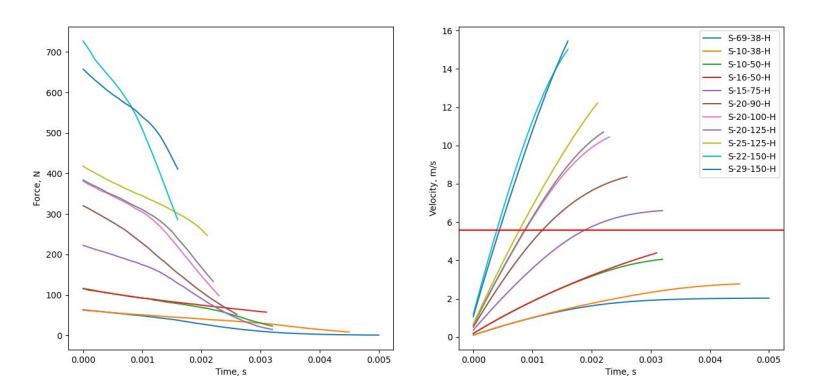
The Generation 0 kicker used a S-22-150-HF solenoid from Magnetic Sensor Systems. This solenoid is very large, and we suspected that a smaller solenoid could be effective. To select our Generation 1 solenoid and prepare for future custom solenoid designs, we worked to model a kicker solenoid using the Finite Element Method Magnetics (FEMM) modelling software and Python. FEMM calculates the instantaneous magnetic force at a specific time given the shape, material, and relative position of the solenoid components along with how much current is flowing through the coil. A Python script wraps the FEMM calculation step with a model of the current through the coil over time and a basic physics simulation step to translate the magnetic force into solenoid plunger motion. This allows us to estimate the speed of the plunger when it strikes the ball. After accounting for inefficiencies in inertial transfer to the ball, we get an estimate of the kick speed. Our results are shown in Figure 4. The red horizontal line marks 5.5m/s, which was our minimum desired top kick speed.
The tool ran on the specifications from a range of solenoids available from Magnetic Sensor Systems and two were selected for physical testing: the S-20-90-H and the S-15-75-H. The tests involved kicking the ball directly with the solenoid plunger (no boot) and recording a video against a scale. The video is used to estimate the ball's velocity leaving the solenoid using the Tracker tool. The results from this testing are shown in Table 2. While errors in the modeling and physical experiment setup are present, it was sufficient to guide the decision to use the S-15-75-H in the Generation 1 kicker. The full source for this tool is available in our hardware analysis repository on GitHub.
Modeled and Measured Kick Speeds
| Solenoid | Modeled Speed | Measured Speed |
|---|---|---|
| S-15-75-H | 5.32m/s | 5.0m/s |
| S-20-90-H | 6.74m/s | 5.8m/s |
The Generation 0 kicker boot was threaded onto the solenoid plunger. This was a challenging machining task given the tools we have available and proved insufficiently robust to survive the force of kicking. The threads quickly sheared off of the boot after only a few kicks. The Generation 1 kicker boot attempted to resolve this by switching to a clamping design. Unfortunately, shortly before the 2023 Bordeaux RoboCup, we found that the clamping boot design was prone to falling off if the kicker fired without a ball to hit. To get through the competition event, the kicker boots were glued onto the solenoid plunger with steel-reinforced epoxy. While effective, this limits our ability to maintain these kickers. The team is investigating ways to address this in our Generation 2 platform.
Electrical
The A-Team electrical system consists of 5 main Printed Circuit Boards (PCBs): Control, Kicker, Radio, IMU, and Breakbeam. The latter three serve as breakouts to allow easy servicing and future upgrades. The control board was detailed in last year's TDP.
Philosophically, the team separates boards into major functions. The control board handles radio communications and the kicker board handles all ball detection and manipulation, including breakbeam and dribbling.
Control Board Reliability
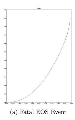
The control board implemented in last year's TDP had probabilistic failures of the power protection front end. These were correlated with plugging in new batteries over several dozen swaps. The problem was not reproducible on a power supply when debugging until the team noticed that hot plugging the power supply would nearly always destroy the power protection circuitry. Further investigation revealed this is to be Electrical Over Stress (EOS) failure in a realm between normal operation and Electro-Static Discharge (ESD). EOS events are characterized by a voltage spike longer in duration and lower in voltage than ESD events, and the typical cause is the power wire parasitic inductance interacting negatively with capacitance dropoff of the bulk capacitors as the DC voltage rises in a battery hot-plug event (slew rate is uncontrolled). This modeling is not included in the default SPICE model of a capacitor, and the effect is difficult to instrument on an oscilloscope. Upon learning about the effect, the team modeled higher order effects in SPICE to develop a counter measure. Correctly implementing the new capacitor models showed catastrophic failure of the system in Figure 5a. A spike of 72V, three times the battery voltage, is seen before SPICE crashes because the model is no longer valid at that voltage. A first-order linear voltage dependence as described by Analog Devices and shown in Equation 1 was used as the refined model for simulation.
$$Q(V_{bias}) = V_{bias} * C(0) - \frac{1}{2}V_{bias}^2 * \frac{C(0) - C(V_{max})}{V_{max}}$$
The team added a current limiting resistor to the power front end protection IC power pin, and added a TVS diode after the current limiting resistor. Adding a TVS diode without an accompanying current limiting resistor causes the event to occur multiple times. The team also added an RC snubber with a resistor from the Yageo SR series, specifically designed to withstand high impulse power. This was re-simulated in SPICE and it resolved the reliability issue as shown in Figure 5b.
Kicker Board
The A-Team kicker board was designed to prioritize safety and rapid charging above size minimization. As a new team, there was a consensus that robots would miss kicks with high probability during controls and gameplay development, and during matches. Being able to charge quickly to re-attempt kicks with a consistent (full) charge level was a high design priority. A high current (50A primary) transformer was chosen to allow high charge currents, reducing charge time. To support the safety objective, the team chose a DC-isolated flyback converter design to prevent catastrophic overvoltage of the battery rail should the boost rectifier diode fail in the closed position. The feedback network is not-isolated, which was deemed an acceptable risk because resistors rarely fail closed.
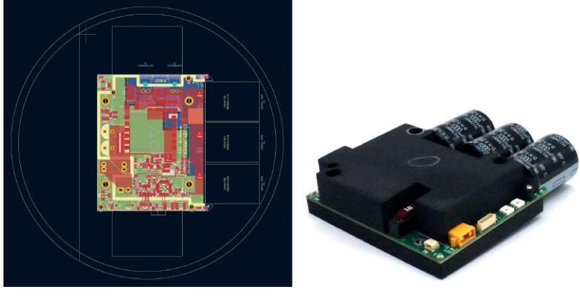
The Generation 1 design also includes a micro-controller and UART interface which makes it generalized with other UART headers on the control board. It makes the exploration of future kicker designs and topologies much easier, as long as they include an STM32 based MCU capable of being programmed over UART. This was important, as the team intends to move all functionality for ball manipulation to the "kicker board" in the future, including the dribbler motor controller and current sensing to more tightly couple ball detection, control, and kicking. Doing so will also help electro-mechanically isolate the ball manipulation components of the robot, allowing entire units to be swapped for maintenance or the exploration of new ideas. The board size profile and final product is shown in Figure 6.
Kicker Board Attributes
| STM32F030 | |
|---|---|
| DC-Isolated Flyback | |
| LT3757 | |
| 190V | |
| 48A | |
| 3000µF 200V | |
| 400ms |
Platform Improvements
Based on the relative success of our 5GHz WiFi radio choice, the team developed more advanced communications approaches to improve reliability and debugability of the system.
Radio Communication Architecture
Based on the relative success of our 5GHz WiFi radio choice, the team developed more advanced communications approaches to improve reliability and debugability of the system.
Discovery
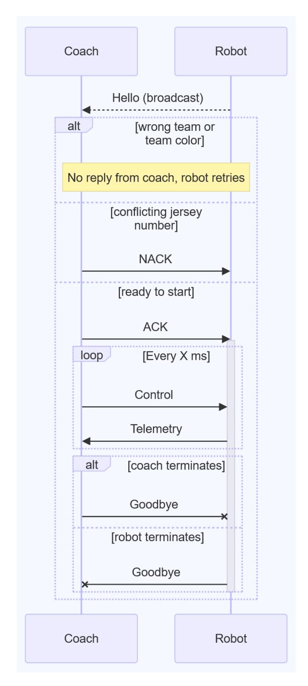
This year's first major advancement was at the protocol level: changes to support multi-fleet and multi-team robot discovery without any hard-coded IP addresses for the robots or coach computer. Upon boot up, the robots initiate a discovery ping over multicast or broadcast containing their DHCP allocated IP address, team name, team color, and robot ID. The team color and robot ID are set using switches or shell ID on the robot. Coach computer(s) can see these hello messages and initiate control, or decline if the robot belongs to another team, or has a configuration error (wrong team color or duplicate ID). This discovery protocol was essential to self-scrimmage, where two instances of the team's software control two fleets of the team's robots. Requiring firmware or software updates to change static IPs was unacceptable for ease of setup when laptops or robots need to quickly switch teams or leave for repair. This has directly allowed the team to address control and reliability issues at scale through routine self-scrimmage. It also serves as a foundation for a league-wide field network as it can already differentiate teams and colors, as well as detect and mitigate configuration errors.
Real-time Telemetry
Routine self scrimmage allowed the team to isolate kick and movement inconsistencies to low level control problems, but a lack of good visibility into the internal control state of multiple robots made these problems challenging to address. Data could not be off loaded from the robots in real-time and was difficult to synchronize with the ROS2 messages used by the coach software. To rapidly analyze robot control performance and iterate, the team implemented real-time telemetry and debug data offload utilizing the extra bandwidth of the 5GHz WiFi radio. The control parameters offloaded are shown in the packets in Figure 8, and include raw and filtered sensor data, control and estimation internals for body and wheel control loops including torque. The team is able to offload this data from at least 6 robots at 100Hz in real-time. The team's radio bridge ingests it into the ROS2 ecosystem for plotting and debugging, the details of which are discussed in Section 2.2.
struct ControlDebugTelemetry {
  MotorDebugTelemetry motor_fl;
  MotorDebugTelemetry motor_fr;
  MotorDebugTelemetry motor_br;
  MotorDebugTelemetry motor_bl;
  float imu_gyro[3];
  float imu_accel[3];
  float commanded_body_velocity[3];
  float clamped_body_velocity[3];
  float body_velocity_state_est[3];
  float body_velocity_u[3];
  float wheel_velocity_u[4];
  float wheel_velocity_clamped_u[4];
} ControlDebugTelemetry;

typedef struct MotorDebugTelemetry {
  float wheel_setpoint;
  float wheel_velocity;
  float wheel_torque;
} MotorDebugTelemetry;
The team was similarly limited by the inability to view and update robot control tuning parameters in real-time over-the-air (OTA). Protocol packets and firmware support were added for the real-time reads and writes of all tunable PID constants, Kalman Filter parameters and matrices, and velocity and acceleration limits. This can also be done for all 6 robots at once.
Motion Control
Motion control tuning has provided the single largest jump in capability post competition. Rapid tuning and data analysis, enabled by the work in Section 2.1, was methodically conducted for the global vision filter, robot body position controller, robot body velocity controller, robot velocity state estimator, and the wheel level PID using real-time data analysis. While we have seen many teams discuss control architectures, few provide guidance on in-situ tuning using real data. The team wrote an initial implementation to utilize these controllers at RoboCup 2023, but still observed a large amount of deviation from our robots' commanded paths.
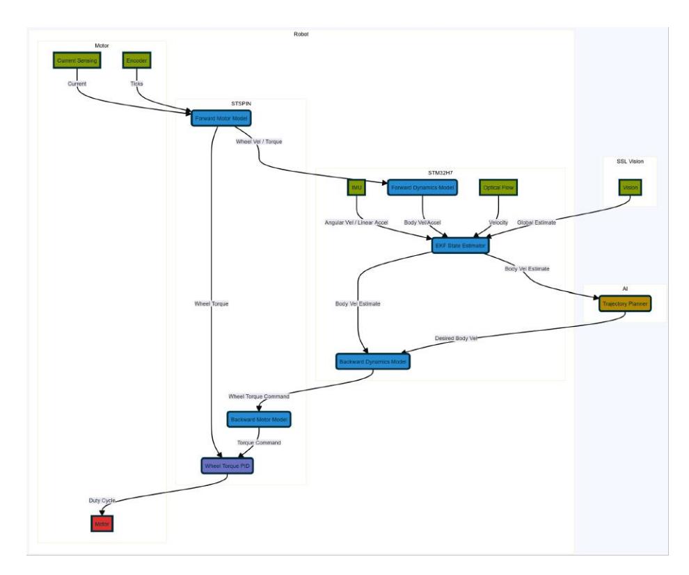
Below are discussions and examples of real-time plots of errant behavior, and the steps taken (often by intuition) to rectify problems. The overall robot control architecture is shown in Figure 9. The team examined control data sources utilizing the ROS tool "PlotJuggler", which plots, records, and replays values of ROS messages from our software in real-time.
A corpus of diagnostic controls plays enabled the team to isolate specific problematic motions. The team's list of simple reproducible trajectories is:
- spinning in place
- driving in a straight line
- strafing in a straight line
- driving around a fixed size square facing a constant direction
- driving around a fixed size squares facing the next waypoint
- driving the maximum field diagonal length facing a variety of specific points statically and dynamically
Using trajectories 1, 2, and 3, tests can be conducted using only on-robot velocity control or using both onboard velocity control and vision-enabled position control. Trajectories 4, 5, and 6 require vision-enabled position control. As such, 1, 2, and 3 form the backbone of the debugging suite.
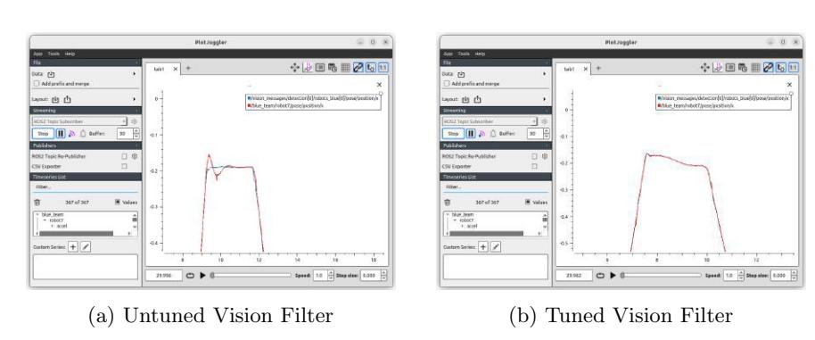
The first major observed issue was oscillation in theta velocity and position. The team started by trying to tune our position and velocity controllers, but we struggled to find satisfactory parameter values. Rendering raw and filtered vision data in PlotJuggler revealed problematic latency and oscillations being introduced by the vision filter. This manifested as a state estimation oscillation, which induced a position controller oscillation as well. This is visible in Figure 10a. The team discovered an incorrect formulation in the filter and poorly tuned observation covariance causing high latency. The team resolved these issues quickly with the aid of real-time plotting. The filter output better matched noise-free input, as shown in Figure 10b, and there was a noticeable improvement in motion quality.
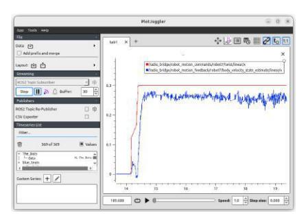
Similarly, real-time plotting allowed the team to fix velocity loop tuning as shown in Figure 11. It was clear that on kicking skills the robot wasn't completely making it to the commanded position, and the team suspected the position controller needed a stronger integral component, but this caused jitter. Further inspection showed the velocity controller had an insufficient integral term, that was making the position controller output ineffective. The velocity responses before and after tuning are shown in Figures 11a and 11b respectively.
The team highly recommends investment in wireless real-time control telemetry for new teams and leveraging general and ROS2 infrastructure to avoid duplication of effort where possible. The ability to quickly gather and analyze this data has been the single biggest factor in improving motion quality and play reliability in the past year.
Software
In preparation for the 2023 Bordeaux RoboCup event, the team laid a solid software foundation using the Robot Operating System (ROS). The core nodes the team wrote for connecting to the league protocols and our robots worked well. The gameplay code underwent a complete rewrite during the event and has been steadily improving ever since.
"Kenobi" Gameplay Module
In our 2023 TDP, we presented an architecture for gameplay code called DAG(t), which used ensembles of directed acyclic graphs to compose arbitrarily complex play behaviors. While the team believes in the eventual potential of this approach, it proved difficult to achieve a minimum viable product with DAG(t). In order to participate in competitive matches, the team created a new software package during competition, nicknamed "Kenobi", using a more traditional skill-tactic-play (STP) approach. This included game state evaluation, play selection, path planning, and position level motion control. Utilities were written to track when the ball is in play and which robots are bound by the double-touch rules at any given time. Unsurprisingly, with almost 7000 lines of code written in the span of about a week during the competition, bugs were plentiful. Much of our time since the 2023 Bordeaux RoboCup event has been spent fixing many small bugs and making improvements to the Kenobi system for better gameplay performance.
Path Planning
The team also found itself in need of a minimum viable path planner during the 2023 competition event. The team implemented the simple sub-goal based path planning algorithm presented by STOx in their 2014 ETDP. This algorithm is fast, efficient, and particularly well suited to the sparse planning environment present in RoboCup SSL. The team has found good results with this algorithm and intends to keep using it going forward.
Exploratory Research Topics
This section covers research topics the team explored.
Pressure Gradient Dribbling Device
Reliable ball control is essential for robots to successfully execute tactics throughout a match. Common high level objectives of a dribbling device include features to maintain contact with the ball, absorb the impact energy of an incoming ball, and laterally center the ball. The proof of concept explored here primarily focuses on two of the three features listed: maintaining contact and lateral centering. Impact absorption will be an independent feature that is later added onto a revised version.
From an abstract design perspective, the two examined features (maintaining ball contact and centering the ball) can be combined to "moving the ball to the center of the dribbling device." Translating this objective into design constraints, a necessary requirement is a mechanism in which a point-to-point attraction force is applied. Forces described by Newton's law and Coulomb's law are such examples, but neither are directly applicable in this scenario, as the mass of the ball and the net charge of the ball are unfortunately too small. Incidentally, this low mass contributes to a low mass-to-surface area ratio. As such, air pressure gradients can be considered to provide a sufficient force while still roughly having a point-to-point nature. Fig. 12 shows a proof of concept dribbling device that uses the difference in air pressure to accomplish the objectives listed above. The test unit uses a single 40mm fan to blow air out of the dribbler duct, which creates a relative negative pressure region inside, based on Bernoulli's Principle.
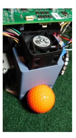
With the 80/20 ball occlusion rule, the robot can only cover up to 8.534mm of a 42.67mm diameter ball. The circular cross section that divides the 80% side and the 20% side will then have a diameter of 34.13mm and an area of 9.149×10⁻⁴m². Since the net pressure will cancel out everywhere else, the product of this area and the static pressure generated yields the magnitude of the force applied to the ball. Given the mass of the ball, 45.9g (0.4501N in weight), a fan that can generate a static pressure higher than 492.0Pa can maintain control of the ball on a floor surface with a coefficient of friction less than 1. It should be noted that this force is the theoretical maximum force and is only observed when the ball completely blocks the air channel.
Since physically possible but rule violating mechanisms are not allowed, rule adherence must be checked. Section 3.2.3 of the rules outlines the requirements for a dribbling device. With regard to the degree of freedom rule, none of the ball's rotational axes will be constrained. With regard to the elevation rule and the 80/20 rule, these must both be followed by adjusting the front-side geometry to ensure the ball is not occluded and the center of the air inlet is not above the ball's center. Finally, with regard to the ability for another robot to be able to remove the ball, the combination of the 80/20 rule and the degree of freedom rule already satisfies this condition.
Optical Flow Velocity Sensing
Last year the team began working with optical flow velocity sensing and was interested in exploring the topic again this year. We previously explored using PMW3389DM-T3QU, which is typically used in computer mice. Very early work showed promising results. However, we had concerns with the sensor requirements of keeping it level and at a consistent 2mm vertical height given the rough texture of the competition field.
The team decided to explore using the PAA5100JE-Q optical tracking sensor. This sensor measures a change in distance similar to a mouse sensor. The product is targeted at mobile robotics such as robot vacuum cleaners with support for sensing on carpet. While it is still required to be level to the measurement surface, the sensor is able to operate from a range of 15-35mm. The vertical axis being less constrained seemed more conducive for a leveling system. The sensor does have a major downside: its max rated velocity sensing is constrained to 1.14m/s; however, the team believes optical flow sensors are best compensating for encoders' propensity to slip and vision's higher latency.
Field
The team has found 2' x 2' re-configurable carpet tiles that are cheaper than carpet in most cases and closely meet previous competition field materials. These tiles are easy to place down temporarily for teams that cannot have a permanent field setup. They are also highly portable and damaged areas can be easily repaired by replacing individual tiles. The team recommends them as an excellent alternative to sourcing bulky and expensive local carpet every year for RoboCup SSL events.
Open Source
Mechanical, electrical, firmware, software, and control and circuit models are published on the team's GitHub page and licensed for broad use. Competition versions are documented with known issues and production artifacts for replication.
References
- S-15-75-H Solenoid Datasheet, http://www.magneticsensorsystems.com/solenoid/tubular/s-15-75-h.asp
- S-20-90-H Solenoid Datasheet, http://www.magneticsensorsystems.com/solenoid/tubular/s-20-90-h.asp
- S-22-150-HF Solenoid Datasheet, http://magneticsensorsystems.com/solenoid/tubular/S-22-150-HF.asp
- Tracker: Video analysis and modeling tool, https://physlets.org/tracker/
- SSL-A-Team Onshape 2023 Robot (2023), https://cad.onshape.com/documents/0fabd67c37f82a8258469ff7
- SSL-A-Team GitHub Organization (2024), https://github.com/SSL-A-Team
- SSL-A-Team Hardware Analysis Repository (2024), https://github.com/SSL-A-Team/hw-analysis
- Avidano, C., Barnette, S., Barulic, M., Medrano, L., Neiger, J., Osawa, R., Peterson, E., Spall IV, J., Spalten, J., Stuckey, W., Woodward, M.: The a-team technical description paper 2023 (2023), https://ssl.robocup.org/wp-content/uploads/2023/02/2023_TDP_The_A_Team.pdf
- Browning, B., Bruce, J., Bowling, M., Veloso, M.: Stp: Skills, tactics and plays for multi-robot control in adversarial environments (2004), https://kilthub.cmu.edu/articles/journal_contribution/STP_Skills_Tactics_and_Plays_for_Multi-Robot_Control_in_Adversarial_Environments/6561002
- Devices, A.: How to Use LTspice Simulations to Account for the Effect of Voltage Dependence (2021), https://www.analog.com/en/resources/analog-dialogue/raqs/raq-issue-192.html
- Faconti, D.: PlotJuggler (2024), https://plotjuggler.io/
- Mats, W.S.: 3/8in Thick Carpet-Top Mats (2024), https://www.wesellmats.com/products/10mm-thick-carpet-top-mats?variant=41651261636815
- Meeker, D.: Finite Element Method Magnetics - User's Manual Version 4.2 (2020), https://www.femm.info/wiki/HomePage
- PixArt: PAA5100JE-Q (2024), https://www.pixart.com/products-detail/74/PAA5100JE-Q
- PixArt: PMW3389DM-T3QU (2024), https://www.pixart.com/products-detail/4/PMW3389DM-T3QU
- Richtek: Analyzing VIN overstress in Power ICs (2016), https://www.richtek.com/Design%20Support/Technical%20Document/AN048
- Rodrıguez, S., Rojas, E., Perez, K., Lopez, J., Quintero, C., Calderon, J.M.: Stox's 2014 extended team description paper (2014), https://ssl.robocup.org/wp-content/uploads/2019/01/2014_ETDP_STOxs.pdf
- Senthilkumarb, A., Sidhuf, A., Balamuralia, A., Sturnc, D., Antoniukf, D., Tof, D., Muhstaqb, F., Cremad, F., Bryantb, H., Rovnerg, H., Lewb, J., Wakabad, K., Zareiana, N., Levyf, O., Khanf, R., Caod, R., Nedjabatb, R., Kongb, T., Ajmald, S., Lye, S., Zhouf, Y.: 2023 team description paper: Ubc thunderbots (2023), https://ssl.robocup.org/wp-content/uploads/2023/02/2023_TDP_UBC_Thunderbots.pdf
- SSL, R.: Rulebook for 2023 (2023), https://robocup-ssl.github.io/ssl-rules/2023/sslrules.pdf
- Yageo: SR Anti-surge Chip Resistor (2024), https://www.yageo.com/en/Product/Index/rchip/surge