2024 Team Description Paper: The Bots
Akhil Veeraghanta, Henry Bryant, Simon Zheng, Mathew MacDougall, Marcus Lee, Steven Guido, Liam Bontkes, Willem Van Dam
https://github.com/sfunderbots · https://cad.onshape.com/documents/f50de4495ca6813b0d6d1926
Abstract This paper details the design and development of the systems of The Bots, a Small Size League team intending to compete in RoboCup 2024 in Eindhoven, Netherlands. We introduce a unibody drivetrain frame, new sub-wheel designs for our omni-wheels, flexure based dribbler damping, "power pillars" to improve cable management between PCBs, a quick release battery cage, smarter capacitor discharging, improved motor drivers, an optimized pass evaluator, and software based automatic robot ID assignment.
Keywords: RoboCup 2024 · Small Size League · Robotic Soccer · Pass Evaluation · ID Assignment · Battery Replacement · Cable Management · Omni-wheel · Damping
Introduction
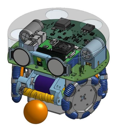
The Bots is an interdisciplinary team composed of university graduates who were formerly part of the UBC Thunderbots Design Team, as well as having recruited graduates from other Universities in the USA. Established in 2022 after RoboCup in Bangkok, Thailand, the team is now pursuing its first competitive action within the Small Size League seeking qualification for RoboCup 2024. One of the barriers of entry into the league is the development cost. The Bots has come up with a cost-optimized design, describing multiple optimizations for the league. This paper outlines The Bots' progress in developing the mechanical, electrical, and software systems of these robots to compete in RoboCup 2024.
Mechanical
Unibody Frame
We are using a single piece of folded sheet metal as our baseplate, motor mounts, and as the joint between our mechanical components and electronics. This approach has been seen before by luhbots. [14] The benefit of this approach is the reduced cost of sheet metal manufacturing compared to traditional 3d parts. One foreseeable drawback to a unibody design is that the bends in the thinner material might be vulnerable to plastic deformation during impacts. If unwanted bending becomes a problem we plan to increase the stiffness of the affected sections by forming ribs, gussets, or flanges, or by welding in more material.
Kicker Head
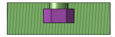
The current kicker system is actuated by an off the shelf solenoid. This leaves the kicker head as the only custom designed component. The kicker head is a single part 3D printed out of PLA with a captive nut shown in figure 2.1 which provides threads for attaching it to the solenoid plunger.
Dribbler Assembly
Our dribbler system uses a single 3D printed frame to house all of its components instead of fixing parts between two parallel plates as seen with other teams such as UBC Thunderbots. [1] 3D printing reduces our reliance on custom machined parts making it simple and cost effective for each member of our geographically distributed team to build dribblers.
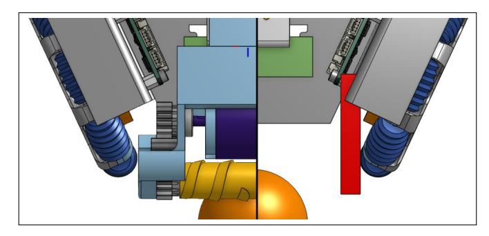
Our design uses a tapered dribbler frame which narrows from the roller to the motor as shown in figure 2.2. We opted for this shape because of space constraints. High costs limit us from using narrow motors with outer diameters similar to the dribbler roller which would allow us to place the motor directly above the roller. Instead we are using larger motors meant for RC aircraft. The large sizes of our drive train, kick solenoid, and dribbler motor does not leave enough room for our dribbler system to be supported by a parallel plate mounting system while maintaining a wide roller. The non flat shape of our dribbler frame would normally be more difficult to machine but is easily achievable with 3D printing.
Damping
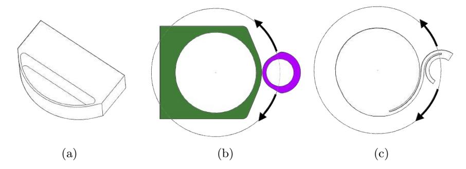
We plan to integrate the damping for our dribbler system as compliant mechanisms 3D printed directly into the frame. Our intent is to have a two Degrees of Freedom (DoF) solution with the first being a linear DoF where a leaf spring allows the entire dribbler system to travel backwards towards the rear of the robot and the second DoF is a compliant bearing where a compliant band provides a restoring force as the dribbler roller is free to roll on along a circular path centered on the motor. This is kinematically equivalent to a rigid body mechanism where the dribbler roller is attached to a rigid link which is also connected to the motor through a pivot centered on the shaft with torsion springs applying the restoring force. Figure 2.3 illustrates the damping mechanisms. Having more than one independent spring in our two DoF solution will allow us to optimize the dribbler's frequency response to minimize vibrations from the motor and compensate for a potential lack of stiffness in the compliant band. Fully integrating damping into our frame reduces the number of parts and has the potential to further simplify assembly and free up space near the front edge of the baseplate and midplate where damping, kicking, chipping, and breakbeam mechanisms are commonly mounted.
Omni-wheel
We designed our wheels to be 3D printable, and attach directly to the motors, which significantly reduces the cost and complexity of our drivetrain. We optimized the sub-wheel size and count for ease of manufacturing, without compromising smooth movement. We ensured that each sub-wheel hands off traction to the next sub-wheel, with enough overlap. We plan to continue to investigate the best flexible filament to print the sub-wheels with and what sub-wheel surface creates the most static friction.
Traction
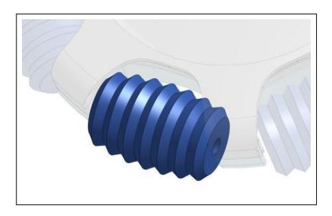
Figure 2.4 Shows our first exploration into the design space. Note the ribbed tread. Our theory is that a sub-wheel with a tread pattern will have better traction than a smooth wheel. It seems that the static friction coefficient between the wheel and the playing surface is the greatest factor for max acceleration, but by using a non-flat sub-wheel, the sub-wheel should make some contact with the playing surface that is not just parallel to the ground. This will mean that some of the normal forces the wheel makes with the play surface will have a component vector that is in the direction that we are trying to accelerate. Our first set of sub-wheels are printed with 85A TPU. Our initial iteration of the wheels can be seen in our qualification video.
Assembly
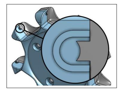
Each sub-wheel has its own metal axle that is clamped in place and offset from the mating seam of the two halves of the wheel (see 2.5). The subwheel mounts to the axle via 2 super small bearings at each end of the sub-wheel.
Electrical
Electrical System Overview
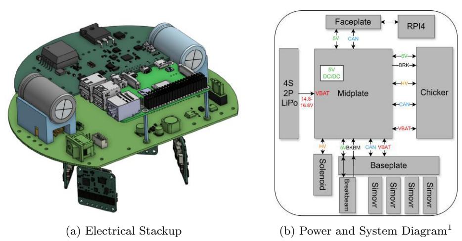
The designs we are proposing for the electrical stackup incorporate low-cost design aspects, towards our overall goal of making each robot cost around $500 USD. After attending RoboCup with Thunderbots in 2022-2023 it was clear the electrical redesign from 2022[1] and 2023[15] proved increasingly difficult to solve the cable management problem. There were various wires connecting between PCBs, and in some cases, the wires would get damaged when packed tightly to put the shell on. To mitigate this issue when designing our robot, we are implementing a minimized cable design by using a robot-wide CAN bus, such that there are very few inter-board connections. It should also be noted that the stackup will be largely PCBs, to minimize machining costs and to implement our modular design. The electrical design we will use for RoboCup 2024 is shown in figure 3.1a and explained in table 1, with the system diagram[1] in figure 3.1b. All projects were designed in KiCad for their free open-source software.
Electrical Stackup 2024
| Project Name | Description |
|---|---|
| Midplate | Power distribution, 5V DC/DC converter for Faceplate and Chicker |
| Board, CAN bus routing | |
| Faceplate | IMU, Camera, Displays, Radio, Connection to RPI |
| Raspberry Pi 4 | Off-the-shelf Raspberry Pi for main control |
| Chicker | High Voltage DC/DC Flyback Conversion, Solenoid Driver |
| Motor Driver | Custom TinyMovr motor drive, including magnetic encoder |
| circuitry, direct drive motors | |
| Baseplate | Power + CAN routing from Midplate to motor driver |
| IR Transmiter and Receiver for ball detection |
Midplate
To achieve a low-cost and minimized cable design for our robot, we decided to use a PCB as our midplate, with power from the battery using a clip-in battery cage at the back of the robot. This is routed on a 4-layer board, with a rocker switch on the side to control power to the robot.
Power Pillars
To further reduce cables, we opted to choose a novel method for power and signal transfer from the midplate to the chicker board, by using standoffs as "Power Pillars" to conduct electrical current. Using M2.5 brass standoffs, we calculated the resistance through the standoff based on its height, area, and worst-case resistivity of brass[7], shown in equation 1:
$$R = \frac{\rho L}{A} = \frac{\rho L}{A_{hex} - A_{circle}} = \frac{0.9 \times 10^{-7} \Omega m \times 25 mm / 1000}{(20.79 mm^2 - 5.31 mm^2) / 1000^2} \approx 1.45 m\Omega \quad (1)$$
Seeing as the overall resistance is very low, we decided using standoffs in our design would not cause any major problems, as long as they are insulated.
Power Pillar Placement
The placement of the power pillars on the midplate are lined up with the chicker and Raspberry Pi, with a few special cases. For CAN, we decided it would be best to have them close together on the LV plane area, to keep the differential signal untouched as much as possible. High voltage was routed on the bottom left of the board, where the separation of the standoffs are 3.3mm, which was determined would be sufficient based on the estimate of a 3mm minimum creepage distance for arcing in 300V systems [9]. To ensure a separation distance of 3mm between any conductors and to minimize the risk of arcing to adjacent copper or metal surfaces, we will use 1000V medium-wall heatshrink in combination with a solid 3D printed enclosure around the standoffs to ensure if a crash happens they would be supported by additional material, reducing the risk of a fracture which could lead to arcing.
Battery Cage & Capacitor Holders
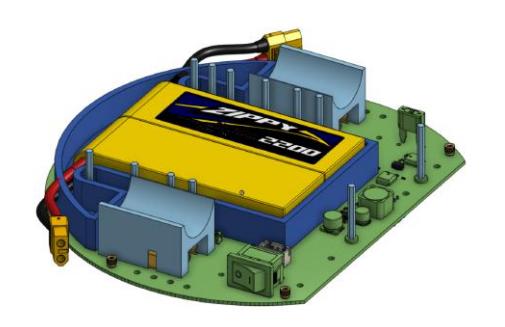
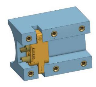
We decided to design a battery cage to provide battery power to the robot in our tight electrical stackup, and give us easy access to replace batteries. Figure 3.2a shows how the battery cage wraps around the standoffs and plugs into XT60 panel mount connectors underneath the cap holders (supporting the Chicker HV Caps) shown in figure 3.2b which are soldered via cables to the midplate. The XT60 male connectors from the batteries are mounted using a flat clamp XT60 holder to the battery cage.
Power Distribution
We decided to put a 5V 3A buck DC/DC regulator on the midplate using the LMR23630A from Texas Instruments which was customized using the TI Webench power designer, supplying 5V to the chicker, faceplate and breakbeam, while still providing battery power to the baseplate and chicker board. All connectors and cables will be routed at the back of the midplate to the baseplate, which will power the motor drivers, breakbeam, and dribbler.
Power Input Discussion
Additionally, the midplate also contains reverse polarity protection that UBC Thunderbots mentioned in their 2020 TDP [6] for their power board. In 2022 and 2023 we noticed that having a blade-type fuse on UBC Thunderbots Power board would blow too slow (270 I 2 s rating) to save a motor from a short circuit current, which would kill motors or damage motor drivers if a motor seized. As such, we decided to research about faster fuses and noticed that automotive blade-type fuses are generally slower than SMDtype fuses. In this light, we decided to change to an SMD fuse on our design, 0501015.WR from littelfuse with a rating of 39.7 I 2 s, which equates to 100ms compared to 675ms for the blade type for a 20A draw.
Faceplate
The faceplate is a board mounted on the front of the robot, which includes a radio module, an IMU, displays, and a forward-facing camera. The radio module being used is the SX1280 by Semtech, used by most teams including Tigers described in their 2018 TDP [11], making sure to keep the ground planes away from the antenna. The IMU on board is the ICM-20689 by TDK InvenSense, which houses a gyroscope and an accelerometer used by TIGERs [12] for a total of 6 axis of motion tracking. The displays are two GC9A01 TFT displays by Teyleten that will update based on robot status and current state. The board is a link to the Raspberry Pi 4 compute node to have direct access to all the sensors with no delay over CAN.
Chicker Board
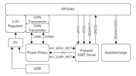
At a high level, the Chicker Board (V1.0) is a high-voltage board with an RP2040 chip that controls the HV circuits, kicking and chipping, and monitors the breakbeam and robot shell status, which communicates with the compute node over a robot-wide CAN bus. The design is similar to UBC Thunderbots from 2023 [15], however the board receives battery power from the midplate instead of regulating it on the board, including some modifications to maintain our costeffective design. The high-level design showing the main functions of the board is described in figure 3.3.
Design Reasoning
The current design uses the LT3750, a boundary mode flyback controller with primary side sensing, using 9A charging to raise the output voltage of the two 1000uF capacitors to 238V in 1.7s. Initially, we had the idea for a SEPIC Multiplied Boost, which was covered in the AN-1126 application note [17] explaining the concept of this design to reduce the stress of high voltage boost circuits: A regular boost or SEPIC converter would require a very high duty cycle, whereas this solution only needs a moderate duty cycle to perform the same function. However, due to the high complexity of this design, we decided to use a well-known solution using the LT3750/51 chips for this year. While the LT3751 charges a capacitor with output regulation using additional safety features (used by most teams such as UBC Thunderbots [6] and TIGERs [12]) we chose the LT3750 due to the simplicity of design which lowers the implementation cost. The output voltage for this converter is determined by the following equation:
$$V_{OUT} = 1.24V \times \frac{R_{VOUT}}{R_{BG}} \times N - V_{DIODE} \tag{2}$$
The recommended $R_{BG}$ resistor value is $2.49 \mathrm{k}\Omega$ [2], which disables charging once the voltage across equals 1.24V. The diode we are using has a forward voltage drop of 1.25V, therefore we can calculate the $R_{VOUT}$ resistance:
$$R_{VOUT} = R_{BG} \times \frac{V_{OUT} + V_{DIODE}}{N \times 1.24} = 2.49k\Omega \times \frac{240V + 1.25V}{10 \times 1.24} = 48.4k\Omega$$ (3)
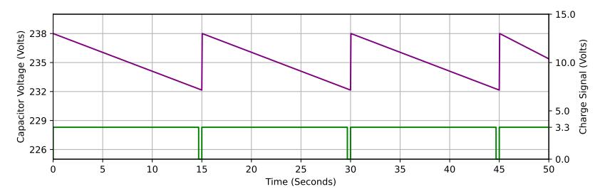
For safety we decided to lower the resistance to $48.1k\Omega$ which will lower the output voltage to 238.2V. The output voltage is then maintained by toggling the charge pin every 15 seconds, equivalent to a drop of $\sim 6V$ , determined from the simulation in figure 3.5.
Discharge Control
A key part of working with high-voltage is safety, thus to ensure the user's safety while using the robot, we have implemented an auto-discharge feature such that when the robot powers off, the HV caps are discharged through high-power resistors. As an extra safety measure, we added an alternative discharge method to control the arming of the HV circuits. Two things will control the discharge circuit: AI can request a discharge for an event such as a substitution, and a hardware reed switch or limit switch attached next to the shell wall will detect the removal of the shell. In either case, it will trigger a discharge of the HV circuits, and disable charging of the flyback controller. The hardware design is largely based on current SSL teams, using two low-threshold MOSFETs to control the discharge through high-power resistors.
Capacitor Mounting
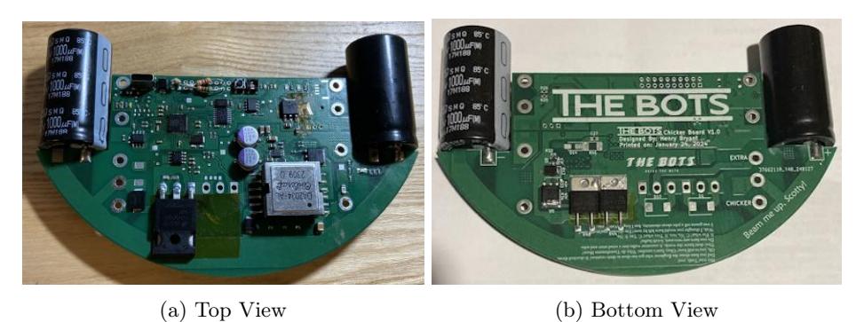
We wanted to ensure that our drive train design could change, without the unrelated electrical components getting in the way. We decided to mount the capacitors sideways on the chicker board, such that the midplate creates a clean separation between the top and bottom halves of the robot. However, this adds two additional problems: additional stress on the mounting pads, and a safety risk from blowing capacitors as mentioned by UBC Thunderbots in 2020[6]. To solve the stress of horizontal capacitors, we oriented them on a diagonal axis as shown in the board reference above in figure 3.4, which has a small indentation that fits along the board to increase the surface area, reducing the likelihood of breakage. In addition, we added a capacitor holder to the midplate to support them, however this is open top and would not prevent damage to adjacent systems if the capacitors were to blow. To prevent this, we plan to add a top piece to the cap holder as a shield to prevent damage in the event a chicker board malfunctions.
Implementation
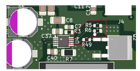
As for the layout of this design, the LT3750 datasheet recommends minimizing the high current path lengths to avoid an overvoltage condition on the NMOS. [2] To avoid an overvoltage situation entirely, we added an RCD snubber to the primary coil of the transformer. The LT3751 datasheet recommends to remove all copper planes underneath the RV OUT and RDCM resistors, [3] we implemented that as shown below in figure 3.6.
Kick Speed Testing
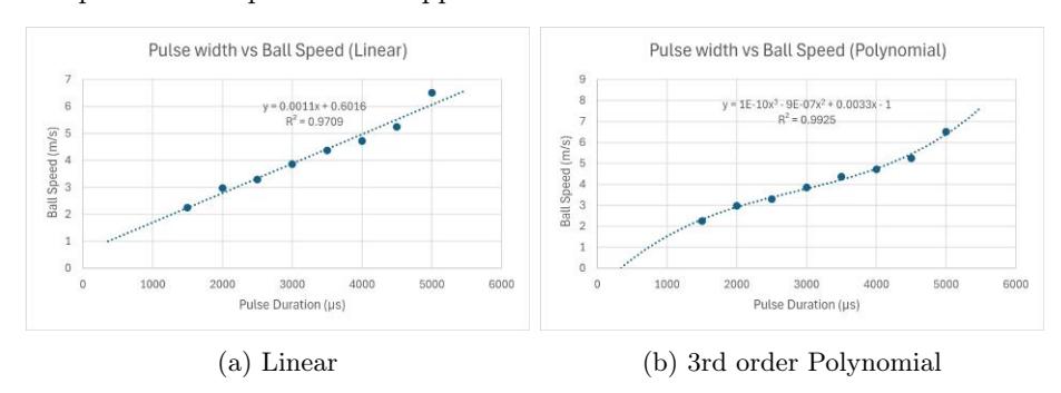
With the chicker board assembled using an off-the-shelf solenoid from Amazon , some basic testing was done to categorize the ball speed compared to the pulse width applied to the IGBT:
Motor Drivers
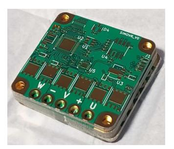
Directly driven wheels benefit from smoother control, especially at slower rotational speeds. This is commonly achieved through sensored field-oriented control (FOC). The motor driver design leverages open-source firmware developed for the TinyMovr project running on the team's own hardware; this firmware library also includes advanced features such as anti-cogging mapping which enables the use of lower cost motors. Some key components choices are highlighted as follows. The core controller - a Qorvo PAC5527 - combines a Cortex M4 processor with a 3-phase gate-drive front end, enabling a small-footprint layout shown in figure 3.8. It is very similar to the STMicro STSPIN32G4 series at a lower cost. The design uses standard power SO-8 mosfet packages (compatible with PPAK, TSDON, etc) for component flexibility, and the MA732 magnetic encoder IC for its competitive cost.
Motors
In an effort to move away from Maxon or similar motors common in the league, and to maximize the benefits of an intelligent motor driver, the team settled on generic 5010 frame size drone motors - commonly available in the 250 - 400kV ( 0.25 - 0.04Nm / A) range at a very low cost - <$20CAD per unit. Mechanically, these motors were selected to maximize space in the interior of the chassis and minimize drive-train weight; the rotor provides the majority of the structure for the wheel, and mounting points for any further components required.
Software
As a new team our focus has been to build a simple and stable software platform upon which we can iteratively improve our gameplay and experiment with novel ideas. As many of our team members are UBC alumni, our software structure is largely similar to that of UBC Thunderbots [4][8][6]. Therefore the following sections only focus on the major changes and improvements we have made over that baseline system.
Heatmaps for Fast Spatial Lookup
Like UBC Thunderbots [5], we use Gradient Descent to optimize a cost-function that informs us where the best pass on the field is. In our initial implementation we found that this optimization was the primary bottleneck in the AI's decisionmaking, taking roughly 35ms. Slow AI decisions result in robots reacting slower to rapid gameplay events, such as the ball entering play or being kicked, so our goal was to improve the performance of our optimization.
The cost-function that was being evaluated had two expensive components: determining the minimum time it would take any friendly robot to reach the specified position, and the minimum time it would take any enemy robot to reach several points along the pass trajectory. Both of these evaluations require iterating over every robot on the field, which is expensive and scales linearly with the number of robots on the field. This could pose additional performance problems scaling to Division A with more robots in the future.
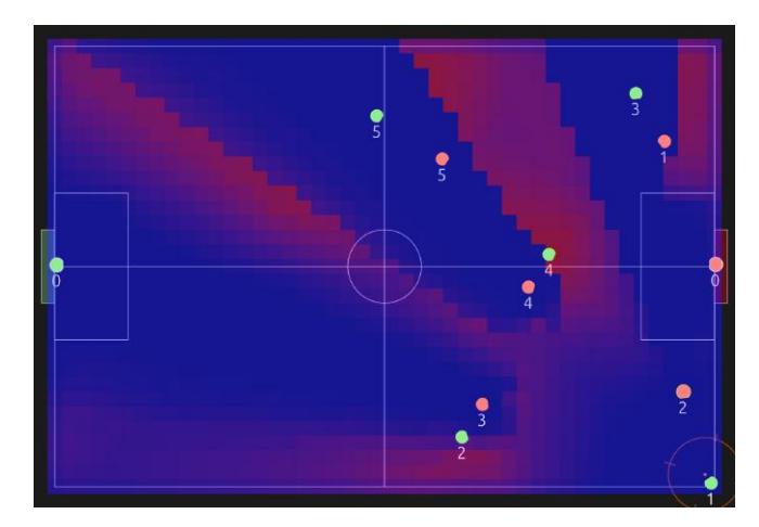
The cost-function does not need to be perfectly precise. It can still be sufficiently optimized if using approximations of its various calculations, such as the time it takes for robots to reach a position. Therefore to solve this performance problem we introduced Heatmaps: 2D lookup tables with highly-parallelizable construction and the ability to smoothly interpolate query results. The field is divided into an equally-spaced grid with a specified resolution, and a function can be sampled to store values at each grid position. This sampling is able to make extremely effective use of parallel computation, which greatly decreases the amount of time taken to populate the Heatmap. When the value at a specific position is requested, the nearby grid values can be smoothly interpolated to approximate the value at the requested position. Our implementation uses bi-linear interpolation for its speed and simplicity, since approximations are sufficient when optimizing passes.
As RoboIME mentioned in their 2019 TDP [13], Heatmaps also make great visualizations that aid developers in visually debugging potentially complex functions.
Automatically Determining Robot IDs
In our system, each robot has a unique wireless ID that the AI uses to communicate with it. It is critical for the AI to know which vision pattern corresponds to which wireless ID so that commands can be sent to the correct robots. Teams often manually set the wireless ID of each robot using DIP switches [16] or touch displays [10] to match the vision pattern on the robot. However, in the fast-paced environment of a RoboCup competition, relying on humans to match a robot's wireless ID to its vision pattern is error-prone. Robots with mismatched IDs will receive the incorrect commands from the AI, leading to degraded gameplay performance while the robot is on the field and requiring extra halts or timeouts from the team in order to remove the robot and correct the wireless ID.
TIGERs Mannheim has solved this problem by reading the vision pattern from the robot cover, so the robot will adjust its wireless ID to match whichever vision pattern is placed on it [10].
We propose a software-based solution that any team should be able to apply to their robots without the need for additional hardware. Our AI sends specific motion commands to each known wireless ID in sequence, and observes which robot executes the specified command. If a robot exhibits the expected motion, we can assume the wireless ID we are communicating with at the time corresponds to the vision pattern of the robot.
A pseudocode outline for matching a vision ID to a wireless ID is provided below:
// On program startup
// Create a table mapping vision ID -> wireless ID
vision_to_wireless = map<int, int>()
current_wireless_id = any wireless ID
// On every program iteration
// Remove any robots that have disappeared from vision.
// They could be off the field and have their vision pattern or
// wireless ID changed.
for vision_id in vision_to_wireless:
    if vision_id is not a currently visible robot:
        remove vision_id from vision_to_wireless
command the current_wireless_id robot to rotate with an angular
speed of X radians/sec
// There can be more robots in the fleet than are currently
// in vision. Make sure to cycle through all wireless IDs
if current_wireless_id has been the same value for over 3 seconds:
    current_wireless_id = next unassigned wireless ID
for robot in visible robots:
    if robot.id in vision_to_wireless:
        continue
    if robot.angular_speed == X:
        vision_to_wireless.insert(robot.id, current_wireless_id)
        current_wireless_id = next unassigned wireless ID
        break
Conclusion
In this TDP we presented innovations made while creating a new RoboCup SSL team. The need for a low-cost construction with minimal machining has lead to a unibody frame for a baseplate and motor mounts, dribbler designs that take advantage of the shapes available through 3D printing, and a new sub-wheel design. Consideration of practical mid-match issues with cable management, battery replacement, and safety brought about quick-release batteries, power pillars to reduce the number of cables between PCBs, and more capacitor discharge triggers. Our pass evaluator is significantly faster with the use of heat maps and we proposed an automated software solution for assigning robot IDs. CAD files for our mechanical design are available on OnShape, and the robot firmware and electrical designs are available on Github.
References
- Almoallim, A., Sousa, C., Sturn, D., Antoniuk, D., Crema, F., Bryant, H., Lew, J., Liu, J., Wakaba, K., Bontkes, L., Zhou, Y.: 2022 Team Description Paper: UBC Thunderbots (2022)
- Analog Devices: LT3750 - Capacitor Charger Controller, https://www.analog.com/media/en/technical-documentation/data-sheets/3750fa.pdf
- Analog Devices: LT3751 - High Voltage Capacitor Charger Controller with Regulation, https://www.analog.com/media/en/technical-documentation/data-sheets/LT3751.pdf
- Buonassisi, A., Chu Lip, O., Deutsch, D., Ellis, G., Goto, E., Hashemi, A., Ivanov, N., Jackson, E., Lai, K., Lee, M., Li, Q., MacDougall, M., Petrie, J., Tonks-Turcotte, K., Sousa, C., Xu, B.: 2018 Team Description Paper: UBC Thunderbots (2018)
- Churchley, S., De Iaco, R., Fraser, J., Ghosh, S., Head, C., Holdjik, S., Ivanov, N., Johnson, S., Kalla, F., Lam, A., Long, B., Lu, K., Ng, S., Peri, K., Petrie, J., Roach, E., Su, W.Y., Wang, B., Xi, C., Yu, K., Zhang, K.: 2015 Team Description Paper: UBC Thunderbots (2015)
- Dumitru, P., Ellis, G., Fink, J., Hers, B., Lew, J., MacDougall, M., Morcom, E., H., S., Sousa, C., Van Dam, W., Whyte, G., Zhang, L., Zheng, S., Zhou, Y.: 2020 Team Description Paper: UBC Thunderbots (2020)
- Electronics Notes: Electrical Resistivity Table for Common Materials, https://www.electronics-notes.com/articles/basic_concepts/resistance/electrical-resistivity-table-materials.php
- MacDougall, M., Hashemi, A., Lip, O.C., Sousa, C., Sawiuk, H., Whyte, G., Golsteyn, Q., Petzenf, R., Deutsch, D.: 2019 Team Description Paper: UBC Thunderbots (2019)
- NI: Pollution degree rating for electrical equipment., https://www.ni.com/en/support/documentation/supplemental/22/pollution-degree-rating-for-electrical-equipment.html
- Ommer, N., Ryll, A., Geiger, M.: Extended Team Description for RoboCup 2022 (2022)
- Ryll, A., Geiger, M., Carstensen, C., Ommer, N.: Extended Team Description for RoboCup 2018 (2018)
- Ryll, A., Jut, S.: Extended Team Description for RoboCup 2020 (2020)
- S. Cosenza, C., Borges da C., G., Fernandez, G., C. K. Couto, G., G. Gonalves, L., Gomes, H., Germano, L., G. Correa, L., de S. Barreira, L., D. P. de Farias, L., R. L. Rodrigues, L., G. O. C. de Melo, J., Bozza, M., P. de Souza, M., S. M. M. de Oliveira, N., C, B. Silveira, O., P. dos Reis, R., P. de Souza, R., G. S. Dias, S., Nihari, Y., F. F. Rosa, P.: RoboIME: From the top of Latin America to RoboCup 2019 (2019)
- Seegemann, L., Zeug, F., Ebbighausen, P., Waldhoff, L., de Vries, T., Sukkar, M., Känner, M., Weber, J.O.: luhbots soccer team description for robocup 2022 (2022)
- Senthilkumar, A., Sidhu, A., Balamurali, A., Sturn, D., Antoniuk, D., To, D., Muhstaq, F., Crema, F., Bryant, H., Rovner, H., Lew, J., Wakaba, K., Zareian, N., Levy, O., Khan, R., Cao, R., Nedjabat, R., Kong, T., Ajmal, S., Sylvia Ly, S., Zhou, Y.: 2023 Team Description Paper: UBC Thunderbots (2023)
- Torres, E., Aguilar, P., Córdova, A., Ruiz, H., Sánchez, J., Martínez, M., Morales, M., Holland, M., Blackshear, W., Hewell, C., , Weitzenfeld, A.: Eagle Knights 2010: Small Size League (2010), https://ssl.robocup.org/wp-content/uploads/2019/01/TDPs_2010.zip
- Zwicker, B.: AN-1126 Application Note - More Boost with Less Stress: the SEPIC Multiplied Boost Converter (2012), https://www.digikey.ca/en/pdf/a/analog-devices/an-1126-more-boost-with-less-stress