TritonsRCSC 2024 Team Description Paper
Rohil Kadekar, Mohammad Mustahsin Zarif, Akhil Ramshankar, Pranav Mehta, Yushan (Yolanda) Liu, Matthew Charry, Allen Wu, Nick Ji, Terri Tai
University of California, San Diego
Abstract This paper describes the development of our overall robot design, including developments over the past year, and the assembly of functional autonomous robots aiming to compete in the 2024 RoboCup Small Size League tournament in Eindhoven, the Netherlands. Compared to last year's theoretical design with only the drive train actualized for practice, this year's development added more capabilities to our robots. These include, but are not limited to, improvements to obstacle avoidance algorithm, controlled omni-directional movement and PID tuning, shooting decision-making and directional kicking, coordinated passing between two actors, and dribbling while in motion. We took an approach that prioritized mastering basic functionality and largely ignored complex maneuvers and skills.
Introduction
The 2023-2024 season is TritonRCSC's fourth attempt at participating in the RoboCup Small Size League competition. Most of the team leads this year joined the team last year, which allowed them to rework the structure of the team, and streamline each sub-group's work. This helped us to be able to engineer working robots this year. Some highlights of this year's development includes the mechanical design which further modified to facilitate the ease of complex calculations done on the Raspberry Pi and STM32 microcontroller, the dribbler that makes use of rubber for traction, and drivetrain that adopts software PI for stability. As for the kicker, we use a boost converter to charge our capacitor. We decided to perform Body-to-Wheel velocity calculations on the Raspberry Pi instead of the STM32 MCU embedded on the RoboMaster Development Board for faster and easier processing on a more powerful board [6]. Our AI has been redesigned as well, utilizing a Behavior Tree instead of a Skill System [1]. Current work focuses on interfacing between the distinct parts of the design.
Mechanical Design
CAD Design
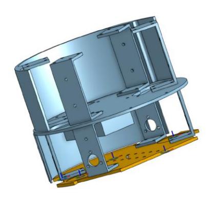
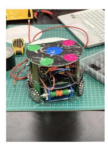
One of our main early considerations was speeding up the prototyping and testing process, which was very slow previously as many of the designs were fully 3D printed. Since our designs consisted of 3 circular flat layers (Figure 1), we decided to opt for laser cutting these layers out of acrylic instead of 3D printing them, which saved us a lot of time when testing new layer designs and mounting configurations. In addition, the 3/16th inch laser cut acrylic proved to be much stronger and rigid than the 3D printed discs we were using with the prior designs.
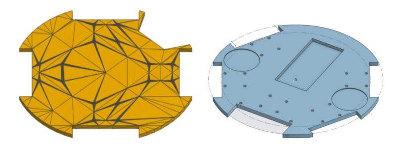
Another major change was switching from a 90 degree motor separation to a design that separated them by 120 and 60 degrees (Figure 2). Initially, we wanted to provide a basic drive train that was easy for the embedded software team to design a controller for motion around. After they were done, we switched to the latter orientation to fit the dribbler, kicker, and battery on the first layer.
Furthermore, we are using the wheel motor mounts as structural support to connect the first and second layers. Before, we had separate structural components that connected the layers, which were usually weak due to awkward placement. Also, they took too much space out of the small body. Utilizing the motor mounts as structural support allows us to save space and provides even weight distribution. The new structural supports between the second and third layers take their form from the design of the c-shaped motor mounts, obviously being different in that they don't have screw holes and openings for motors. This design allows even distribution of the third layer's weight and provides us ample space in the area between the second and third layer. Currently these mounts/structural supports are 3D printed with PLA; however, we plan to fabricate them with sheet aluminum or steel in the near future.
The final addition we made was a part that fixes the battery in place. We decided to have the battery sit on the first layer of the robot, in between the motors, which keeps the center of gravity low. Thus, we needed some way to constrain it. Ultimately we did this by making a part that hangs down from the second layer which constrains the top half of the battery, preventing it from shifting and sliding.
Dribbler
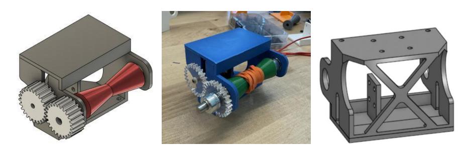
One of our primary objectives early in the design process was to streamline functionality by consolidating the mounting for both the dribbler and the kicker into a single unit. We introduced a ceiling to suspend the motor, thereby freeing up space, albeit requiring the solenoid to be relocated off-center. To address this adjustment, we engineered a small extension platform to augment the contact area between the solenoid and the ball.
Integrating the dribbler and kicker mount with the rest of the robot posed another significant challenge. To circumvent interference from the wheel motors, we strategically removed excess material from the bottom of the mount. To achieve the desired functionality, we also implemented a pair of gears to alter the axis of rotation. Additionally, we designed an X-shaped support structure to fortify the mount against the vibrational forces exerted by the dribbler motor during testing (Fig. 4).
While our prototype featured numerous 3D-printed components, it became evident that the dribbler mount necessitated enhanced durability to withstand the motor's high velocity. Thus, our focus for the final robot iteration will prioritize manufacturing the dribbler mount from metal, ensuring its resilience and longevity in the demanding competition environment.
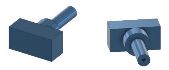
Kicker Plunger
Being able to kick the ball with precision is imperative. With a solenoid being used as the kicker, a "plunger" is mounted onto the solenoid. This plunger, boasting an expanded surface area, significantly facilitates the establishment of contact with the ball, thereby enhancing precision. Through its elongated structure, the plunger optimizes the reach of the kicker, ensuring maximal force transmission upon impact with the ball. By principles of momentum and energy transfer, the distance the solenoid continues to travel impacts the total force exerted onto the ball. When the solenoid initially makes contact with the ball, it imparts a certain amount of momentum to the ball. The force exerted on the ball is determined by the rate of change of momentum, which is directly related to the time over which the force is applied. Therefore, as the solenoid continues to travel forward after contact with the ball, it effectively prolongs the duration over which the force is applied, potentially increasing the overall impulse delivered to the ball.
Relevant equations: $J = F \Delta t$ → Larger change in $t$, larger impulse
Engineered to withstand deformation forces, the plunger incorporates a reinforced ring structure on the shaft behind the main rectangular point of contact with the ball to mitigate the risk of fracture when kicking.
Electronics
Kicker Board
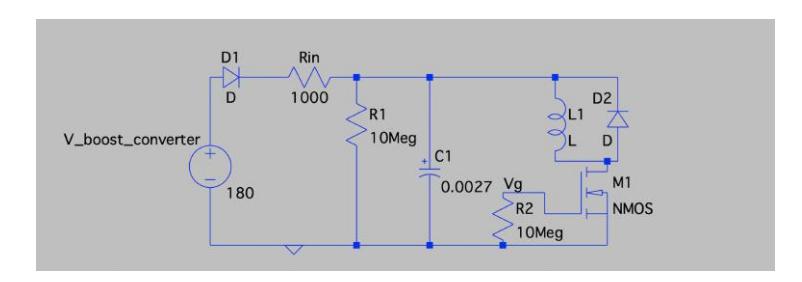
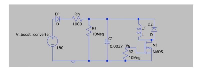
The fundamental mechanism of our kicker board revolves around charging highpower capacitors and swiftly discharging them through a solenoid to achieve rapid extension and retraction of the plunger. We are currently experimenting with the use of high-power boost converters to charge capacitors in a safer manner, and this concept has been successfully implemented.
When initially designing the kicker circuit, we incorporated a capacitor parallel to the inductor solenoid, utilizing a switch to connect the capacitor loop to the solenoid loop. However, we encountered issues with the fuses in our boost converter repeatedly blowing, indicating a current flow exceeding 10A.
Upon closer examination, we identified the absence of a flyback diode parallel to the inductor as a potential cause [12]. Despite adding the flyback diode, the fuse-blowing situation persisted. Subsequent research suggested that the rapid voltage change across the capacitor was leading to a significant inrush current.
$$I_{inrush} = C_{load} \frac{dV}{dt}$$
To address this, we turned to capacitor transient analysis and determined that increasing the time constant of the capacitor was necessary. To achieve this, we introduced an input resistance to slow down the voltage rise time across the capacitor, therefore successfully in mitigating the fuse-related issues.
In the course of our research, we drew inspiration from the kicker designs of other teams, particularly TIGERs-Mannheim [3]. However, we opted for using an NMOS to control the kicking mechanism instead of a BJT. This decision was based on the belief that MOSFETs perform better in high-current, low-kickingfrequency situations—attributes that align with the requirements of the kicker circuit.
In the process of implementing NMOS, we noticed that if we directly connect the gate to the RoboMaster and the ground, we risk the possibility of the gate node having no clearly defined voltage. Therefore, to address this issue, we added a pull-down resistor between the gate of the NMOS and ground to prevent floating node.
Our next steps involve conducting experiments with both BJT and MOSFET as switches to compare their performance, helping us make an informed decision on the best approach moving forward.
Embedded Systems
Embedded systems are responsible for the integration of hardware and software on the robots. Our goal is to establish a robust network of communication between the physical movers of the system, or actuators, and the software-coupled sensors to exchange data efficiently.
Drive Train
We are continuing using DJI Robomaster M2006 P36 Brush-less motors, C610 Electronic Speed Controllers, and the Robomaster Type A Development Board since we made progress with them last year to move our wheels [1].
After monitoring the behavior of our robot's motion with the omni-wheels located at 90 degrees from each other, we increased the angle for the wheels to be at 60 degrees on the left and right and 120 degrees on the front and back to accommodate our dribbler, kicker circuit, and battery on the first level. For initial motion testing, we modeled standardized equations for all axes of motion, and the choice of angles simplified the robot's movement commands. Even then, we had drift when using the simple command of 'move forward,' which is why we wanted to implement a PID control algorithm using motor encoders (Section 4.3).
Communication
For communication between the RM and Raspberry Pi, we have UART with Interrupt working to send and receive signals from the Raspberry Pi 4 Model B. We have been using UART to print debug messages from the RM using PuTTY, so we decided to implement it with the Raspberry Pi to focus on other tasks with higher priorities. Previous teams had planned on establishing USB communication between the two boards; however, UART with a baud rate of 115200 has been proven to be stable and fast enough for our purposes [10].
Ongoing Experiments with Control Systems
As stated in projected goals by the previous year's team, we have implemented a PI algorithm on our embedded systems for better stability during the competition [1]. We use software PI by using data from our encoders as feedback to the motors.
However, we still see some drift in our robot motion, which is anticipated to be a consequence of slow settling time of the PI control algorithm. In order to tackle this, we are planning on introducing the derivative term by differentiating the difference between the encoder data and reference value [11]. To obtain a derivative of the difference, the RPM data from motor encoders will be smoothed through exponentially moving average (EMA): by reducing the discontinuities introduced to the motor encoder as a result of noise, we may calculate derivative values that are within a reasonable range.
As a final step on refining the PID, we will continue experimenting with different P, I and D coefficient values to obtain superior settling times.
Software
General Setup
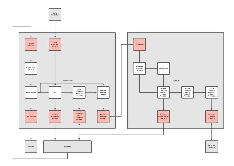
The general software setup continues to be the same as last year's, as illustrated in Figure 8. Both TritonSoccerAI and TritonBot use a simplified Publisher-Subscriber system for convenient inter-modular communications, facilitated via RabbitMQ and User Datagram Protocol (UDP).
TritonSoccerAI Software (Java)
Following last season's AI redesign to a Behavior Tree based system, which allowed for greater speed and efficiency, we have continued to make progress on improving baseline gameplay with changed to our obstacle detection and representation, implementation of coordinated passing, implementation of responses to referee commands, and more.
As we made the choice to have each individual robot run its own behavior tree and therefore make decisions independently, which allows for greater speed but poses robot coordination challenges, we have looked into optimizing coordination-related actions such as moving into formations, passing, and planning and executing plays. While a multi-agent approach is more advanced and more difficult to work with and correctly implement, we believe it is the correct choice as it brings us closer to one our main team objectives: replicating the way humans play soccer.
TritonBot Software (Python)
TritonBot will run on the Raspberry Pi, which is installed on every robot and serves as an intermediary communicator that transmits commands from TritonSoccerAI to embedded systems. To receive the commands from TritonSoccerAI, each robot acts as its own UDP server, receiving commands from the TritonSoccerAI client. The commands received from TritonSoccerAI are vectors in global space that get converted from global space to local space to wheel space by TritonBot's processing modules. Each processing module connects to each other over RabbitMQ which takes the role of an intermediate buffer.
In competition set up, TritonBot now sends motor commands to the embedded systems Robomaster through UART instead of USB, as was the case last year. This mode of communication involves the use of two channels, namely TX and RX, to transmit and receive signals. Specifically, the TX pin transmits signals to the peripheral while the RX pin receives signals. We opted for this mode of communication due to its simplicity in terms of connections, as it requires only a few pins and a single wire. Additionally, since we only intend for the Raspberry Pi to transmit data and for the RoboMaster to receive it, the simplicity of the communication method was deemed sufficient. Despite being an older form of communication, we found available code to establish and facilitate communication between the boards.
Obstacle Representation
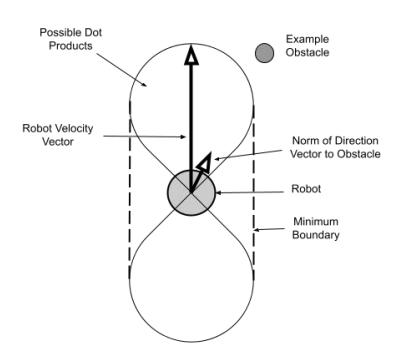
Our previous obstacle-avoidance system incorporated circular-shaped bounds around each robot. The penalty of the nodes within the calculated boundary of each robot was set to be large, so that the algorithm for each robot will choose a path with less penalty and hence will not run into the other robots. However, circular-shaped bounds are quite restrictive, as we realized that we don't need to account for directions the specific robot is not heading towards. For example, if the robot is moving forward, we don't need to avoid the space to the sides of it.
This is why we decided to implement ovular-shaped bounds for each robot, so that we have a maximum radius for obstacles directly in line with the robot and a minimum radius for obstacles perpendicular to the direction in which the robot is heading. See Figure 9. We did this by using the properties of the dot product and the robot's direction and velocity vectors. If the direction vectors between the robot's velocity and the obstacle are in line with each other, the dot product will be its maximum value, meaning that the boundary will be larger in that direction. On the other hand, if the obstacle and robot are perpendicular to each other, the dot product will be 0, meaning we can have a minimal boundary in that direction. Since we don't want the boundary to be absolute 0 at any point, we compare the calculated dot product and a minimum penalty factor, and then take the maximum of the two for the actual penalty factor. We then multiply this factor with a node penalty constant.
This new method allows for obstacles to scale in size based on the velocity of the corresponding robot. In our tests, we have observed that robots often move into closer proximity of others but better avoid collisions in comparison to our previous obstacle representation schema. One of the largest risk factors in competition is the potential for packets to be dropped and information gaps to exist. In comparison to our previous method, our new obstacle avoidance system is far less likely to cause a collision in the case of a lack of new information, and is therefore more resistant to this particular risk factor.
Referee Interaction
Previously, we were missing a GameControllerInterface module, which would be responsible for receiving information from the ssl-game-controller leaguewide shared software. Our lack of ability to receive referee commands from the simulator and test different game states was highly limiting. Our new module receives standard Google Protobuf commands via UDP and writes it to our central information hub from which our AI reads.
With this interface implemented, we started developing responses to all free kick, penalty, kickoff, and ball placement referee commands, which we call specificstate functions. As the previously-delivered command matters upon reception of a NormalStart command, we have accounted for this complexity as well to respond appropriately.
Passing
Implementing coordinated passing was a more complex task that required the use of multiple systems, largely depending on inter-robot communication as well as auxiliary functions. This functionality is a top priority for us as it would allow us to increase the pace of the game and spread the field.
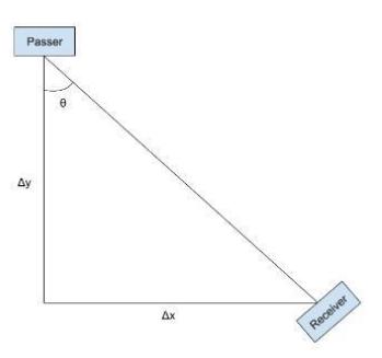
When the coordinated passing action is triggered, a robot needs to decide which other robot is available. To find the best ally, the robot computes scores to determine how "open" and capable of receiving the pass each robot is. The formula for the score is calculated based on a number of factors including the quantity and proximity of obstacles that surround a particular robot and the distance between these obstacles and the path of the ball. We then build a Google Protobuf object which includes the passer's ID, the receiver's ID, and the passing location where the receiver should expect the ball. As of now, the receiving location is just the position of the receiver. However, we plan on developing a more sophisticated system in the future that would allow for through passing. This message is then sent to our central coordinator via RabbitMQ, which then forwards this message to the correct receiver. Beyond messaging, we required an auxiliary function to allow the robot to turn and face the correct direction when passing the ball. To solve this issue, we developed a task node in our behavior tree that would allows our robot to rotate to a specific orientation. To calculate the angle we used the arctangent function as well as the delta x and the delta y between starting and desired positions. See Figure 10. We then use a simple PID-like system to adjust our angle in order to achieve the desired position and execute a proper pass.
In the future, we plan on adjusting our scoring algorithm which is used to determine an optimal receiver. We are also looking into using a more sophisticated system that takes into account future positions of on-field objects and can plan and execute plays that require multiple passes in quick succession. We anticipate this will require further work in recognizing patterns given a particular game state and more complex calculations in determining optimal pass trajectories.
Testing
While understanding and developing our codebase, a key problem has been attempting to identify whether the code we write actually works and is behaving as expected in various scenarios. When simply running our entire behavior tree, the intricacies between the interactions of the various nodes being run as well as the dynamic state of the game objects on the field have made it difficult to pinpoint the effect of our code changes and discern if robot behavior improved. Hence, one area of focus during this year's code development has been creating a better way to test our code.
To accomplish this, we decided to create separate test modules that would be able to run behavior tree nodes and functionalities individually in an isolated environment to just focus on the behavior of one node on one robot at a time. While this method improves our ability to develop better algorithms, it is quite slow and requires human observation of the robots. Hence, improvements include determining if a desired game state has been reached programmatically. This would allow for tests to be run automatically as a part of our continuous integration test suite and prevent breaks of existing functionality.
Hardware Communication
We have implemented a UDP server through which we facilitate communication of commands from our off-field computer running our AI to our on-robot Raspberry Pis over a Wi-Fi Local Area Network (LAN). We specifically configured the server for receiving and interpreting Google Protobuf data.
We also established a stable UART connection between Raspberry Pis and STM32 embedded systems. As a part of this important task, we implemented protocols to convey post-processing data, including wheel velocities, in order to control the robot. Processing of data is expanded upon in Section 5.9.
Processing Pipeline
We have created a new pipeline which handles the processing of commands received from our off-field AI software, the sending of specific wheel and motor velocities to our firmware, and all intermediary steps. Commands are received in the form of Google Protobuf data and contain velocities in the local robot's perspective. Our Python software parses and interprets the command and extracts the relevant information that is needed to perform subsequent calculations.
At this point, we utilize a newly-developed mathematical function to convert these local velocities to velocities for individual wheels. We initially assumed a 90 degree wheel angle configuration where the four wheels were placed equi-distantly around a circular base when performing these calculations. As this configuration did not allow for a kicker and dribbler, we worked on the mathematical function corresponding to a 30-degree wheel angle configuration, which we currently utilize.
$$u_i = \frac{1}{r_i} \left[ 1 \tan \gamma_i \right] \begin{bmatrix} \cos \beta_i & \sin \beta_i \ -\sin \beta_i & \cos \beta_i \end{bmatrix} \begin{bmatrix} -y_i & 1 & 0 \ x_i & 0 & 1 \end{bmatrix} v_b$$
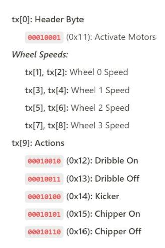
A 10-byte encoding scheme is then utilized to create a packet that is designed for efficiency and clarity of communication to the STM32 board, according to Figure 11 below:
Future Goals
Future Noise Filtration Improvements The accelerations of on-field objects have not been accounted for yet due to significant amounts of noise. The accuracy of both object velocities and accelerations can be increased by improving noise filtration, which we aim to do through the utilization of the Extended Kalman Filter (EKF) algorithm. The EKF algorithm operates by updating its predictions based on measurements and then adjusting, providing more accurate estimates of velocities and accelerations of objects and reducing the effect of measurement noise. This will be particularly important for non-simulation gameplay since there will certainly be a great deal of noise to account for.
Future TritonSoccerAI Improvements During the course of the next few months, we expect many changes will be made to the initial designs of the behavior trees based on the results of testing and simulated gameplay. Algorithms to identify the optimal shot, best pass, or location to dribble towards must all be improved to utilize expected states of the game. In particular, the adding of the capability for a robot to make a through pass—forward pass into a space 0.5 to 2 meters in front of the targeted pass receiver—is a significant priority in order for robots to not be limited to straight-line passes to one another. Positioning when on offense also requires significant improvements as positioning decisions will be made individually by each robot as opposed to a centralized source and is integral to the availability of passing as an offensive option.
Future TritonBot Improvements Communication between TritonSoccerAI software and TritonBot software is one-way; currently, TritonBot only receives commands from TritonSoccerAI. In the future, we plan on adding a line of communication back to TritonSoccerAI through which we send feedback that can be utilized by AI. As a part of this goal, a bi-directional line of communication will also need to be established with robot inertial measurement units (IMUs) to receive positional and orientation data to be sent to TritonSoccerAI.
We also will need to better equip our software with the ability to be resilient to uncertain or unideal conditions. As is critical to performance in dynamic environments, we will need to optimize our pipeline for low-latency scenarios that may unexpectedly arise. In conjunction to this, we may need to implement dynamic protocol adaptation to adjust communication parameters to maximize the flow of information given network circumstances. Further, advanced compression techniques will need to explored and utilized in lieu of our current simple algorithm to minimize bandwidth utilization and thereby increase reliability of communication. Lastly, we will need a robust mechanism to detect and recover from communication errors and noise that may occur to keep our robots continually functioning optimally.
Acknowledgements
We would not have been able to make so much progress without the RoboCup community for the extensive information put online in terms of EDTP, TDPs and GitHub repositories. We would also like to thank TIGERS Mannheim, for their extensive contributions to the RoboCup community and being advocates of open source development. Finally, a big thanks to Nicolai Ommer for his responsiveness and lending of the field camera.
We would also like to thank the UC San Diego IEEE Chapter for their support, guidance, and funding.
A special thanks is due to Professor Amy Eguchi with helping us establish contact with the RoboCup organization and helping the team grow its connections.
References
- Gomes, R., Puneet, Y., et. al.: Triton RCSC 2023 Team Description Paper (2023)
- J. E. A. Araújo et al., "Dribbler and Kicker Systems to Small Size Soccer League Robots: A Study and Project to Latin American Robotics Competition," 2020 Latin American Robotics Symposium (LARS), 2020 Brazilian Symposium on Robotics (SBR) and 2020 Workshop on Robotics in Education (WRE), Natal, Brazil, 2020, pp. 1-6, doi: 10.1109/LARS/SBR/WRE51543.2020.9306957. keywords: Robots;Solid modeling;Three-dimensional displays;Bars;Sports;Mathematical model;Pulleys
- TIGERs-Mannheim. "Tigers-Mannheim/Electronics: Tigers Mannheim Open-Source Electronics." Kicking Device V13b, github.com/TIGERs-Mannheim/electronics
- J. G. Melo et al., "Towards an Autonomous RoboCup Small Size League Robot," 2022 Latin American Robotics Symposium (LARS), 2022 Brazilian Symposium on Robotics (SBR), and 2022 Workshop on Robotics in Education (WRE), São Bernardo do Campo, Brazil, 2022, pp. 1-6, doi: 10.1109/LARS/SBR/WRE56824.2022.9996004. keywords: Power demand;Navigation;Inertial sensors;Machine vision;Robot sensing systems;Finite element analysis;Task analysis
- J. E. A. Araújo et al., "Dribbler and Kicker Systems to Small Size Soccer League Robots: A Study and Project to Latin American Robotics Competition," 2020 Latin American Robotics Symposium (LARS), 2020 Brazilian Symposium on Robotics (SBR) and 2020 Workshop on Robotics in Education (WRE), Natal, Brazil, 2020, pp. 1-6, doi: 10.1109/LARS/SBR/WRE51543.2020.9306957. keywords: Robots;Solid modeling;Three-dimensional displays;Bars;Sports;Mathematical model;Pulleys
- https://www.raspberrypi.com/products/raspberry-pi-4-model-b/specifications/
- https://www.robomaster.com/en-US/products/components/general/developmentboard
- https://github.com/RoboMaster/DevelopmentBoard-Examples
- https://learn.sparkfun.com/tutorials/serial-communication
- Kiam Heong Ang, G. Chong and Yun Li, "PID control system analysis, design, and technology," in IEEE Transactions on Control Systems Technology, vol. 13, no. 4, pp. 559-576, July 2005, doi: 10.1109/TCST.2005.847331. keywords: Three-term control;Control system analysis;Hardware;Automatic control;Pi control;Proportional control;Stability;Computer simulation;Software packages;System identification;Patents;proportional-integral-derivative (PID) control;PID hardware;PID software;PID tuning
- https://www.electronicshub.org/flyback-diode-or-freewheeling-diode/
- Omnidirectional Wheeled Mobile Robots Part 1 of 2." Modern Robotics, Northwestern University, https://modernrobotics.northwestern.edu/nu-gm-book-resource/13-2 omnidirectional-wheeled-mobile-robots-part-1-of-2/department
- https://github.com/dekuNukem/STM32tutorials/blob/master/README.md