2024 Team Description Paper: UBC Thunderbots
Ahmad Abousaleh, Arun Balamurali, Ben Blair, Rocky Cao, Musa Charara, Lauren Chee, James Coffin, Jeanette Guo, William Ha, Florian Haas, Tara Kong, Raiaan Khan, Clinton Lee, Omri Levy, Ryan Nedjabat, Mark Phung, Amtoj Sidhu, Dannon Sturn, Matthew Tong, Boris Vasilchikov, Kenny Wakaba, Nima Zareian, Saurav Banna, Paul Zhou, Yichen Benjamin Zhou
The University of British Columbia
Abstract This TDP details design improvements and innovations UBC Thunderbots has made in preparation for RoboCup 2024 in Eindhoven, Netherlands. The team's primary goal was to investigate and resolve issues surrounding trajectory control and ball placement in the newest generation of robots used at RoboCup 2023. The secondary goal was to innovate on previous systems in these robots for design efficiency and usability. We additionally describe the wide-ranging software architecture improvements to robot software, motion planning, strategy and planning, simulation, and visualization that were implemented since RoboCup 2021.
Introduction
UBC Thunderbots is an interdisciplinary team of undergraduate students at the University of British Columbia. Established in 2006, it pursued its first competitive initiative within the Small Size League at RoboCup 2009. The team has consecutively competed in RoboCup from 2009 to 2023 and is currently seeking qualification for RoboCup 2024. Over the past year, the team has trialed a variety of new solutions and upgrades in pursuit of the Division B title. This paper details UBC Thunderbots' new developments in mechanical, electrical, and software systems to compete in RoboCup 2024.
Mechanical
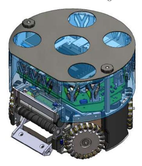
For 2023-2024, our mechanical team has focused on making improvements to our previous robot design, including upgrades to the chipper, dribbler, and chassis system. We have also been improving our robots' robustness and manufacturability by optimizing several component designs detailed in the sections below. Our most recent CAD model is shown below in Figure 1.
Dribbler Assembly
Our previous dribbler system introduced a section for directly hosting the breakbeam control boards. However, issues were found with the wires meshing against our drivetrain wheels. This year, several design changes were made to improve our dribbler.
Internal Gear
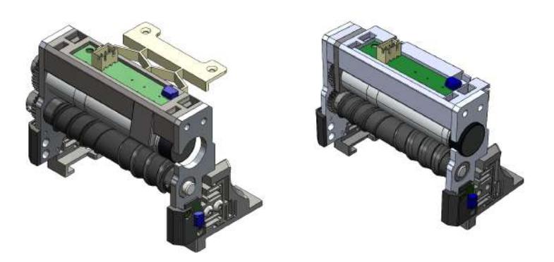
In our previous robot design, the motor and dribbler gears were placed on the exterior of the left dribbler plate. Thus, the wires connecting the break-beam side PCBs to the break-beam control board had to be routed through the back of the crossbar using cable holders extruded out from the rear face of the crossbar. However, during gameplay, loose wires would slip out of the holder through the opening of the cable holder, and get caught in between the gears, effectively interrupting the dribbler and disconnecting the breakbeams.
To eliminate this issue, we modified the crossbar into three different components while maintaining the original length of the dribbler, as shown in Figure 2. We 3D printed the two crossbars and water-jetted the motor mount plate using aluminium to mitigate unnecessary vibrations and potential warping during gameplay. The extruded cable holders on the rear-face of the crossbar have been rotated 90 degrees, and shifted to the top ledge of the crossbar. In addition, the bottom edges at the entrance of the cable holders have been chamfered by 3mm at 45 degrees to prevent sharp edges from cutting into the cables. With these modifications, it allowed us to shift the motor and dribbler gears into the interior of the left dribbler plate. As a result, we are now able to connect the PCB wires directly to the control board without the possibility of them impeding the dribbler gears. The new design can be seen in Figure 2 above.
Testing Rig
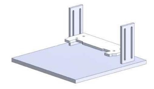
Due to issues with wear on rollers, and inconsistency with centering the ball while dribbling, we wanted to build a test rig to find the optimal roller height. The plan was to create a rig (Figure 3) that would allow us to mount the full dribbler subsystem, and translate it up and down relative to a base. This allows us to run the dribbler at different heights relative to the "ground", independent of the entire robot. To simulate movement, we place a rectangle of carpet beneath the ball in the test rig while it is dribbling, and manually slide the carpet left, right, forward, and backward. This allows us to qualitatively analyze the effects of different rollers at different heights on the ball while the robot is in motion.
Next Steps
By our calculations, the height of the roller center should be 43.94mm from the ground for maximum efficiency. According to the SSL rules, the ball can go in a maximum of 20%.
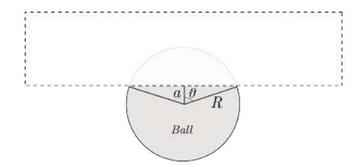
$$\frac{(\pi R^2 - \pi R^2(\frac{2\theta}{2\pi})) + \frac{R^2 \sin(2\theta)}{2}}{\pi R^2} = 80%$$
$$\Rightarrow 1 - \frac{\theta}{\pi} + \frac{\sin(2\theta)}{2\pi} = 0.8$$
$$\Rightarrow \frac{\theta}{\pi} - \frac{\sin(2\theta)}{2\pi} = 0.2$$
$$\therefore \theta = 1.0567 \ rad$$
We then used the $\theta$ above to derive the optimum height:
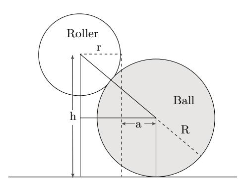
$$cos(\theta) = \frac{a}{R}$$
$$\Rightarrow a = R \cos(1.0567) \ mm$$
$$\therefore h = \sqrt{(R+r)^2 - (r+a)^2} + R$$
We took $R=\frac{42.82}{2}$ mm (Ball radius) and r=7.36 mm (Roller radius). With these values, the maximum height for 80% of the ball being outside of the robot should be: h=43.94 mm. However, after rigorous testing, we observed that the optimum height is slightly lower at 37.50 mm. At heights higher than that, the dribbler has a tendency to "eat" the ball, which then results in a 5th wheel and moves the robot even if we're running a stationary test.
Chipper
The goal for chipper this year was to eliminate inconsistencies between robots, ensure that they don't get stuck after chipping, and produce a simpler, more efficient chipper design. The new design idea is to revert to direct impact or forward moving chipping systems to resolve these issues and potentially create a more powerful chip.
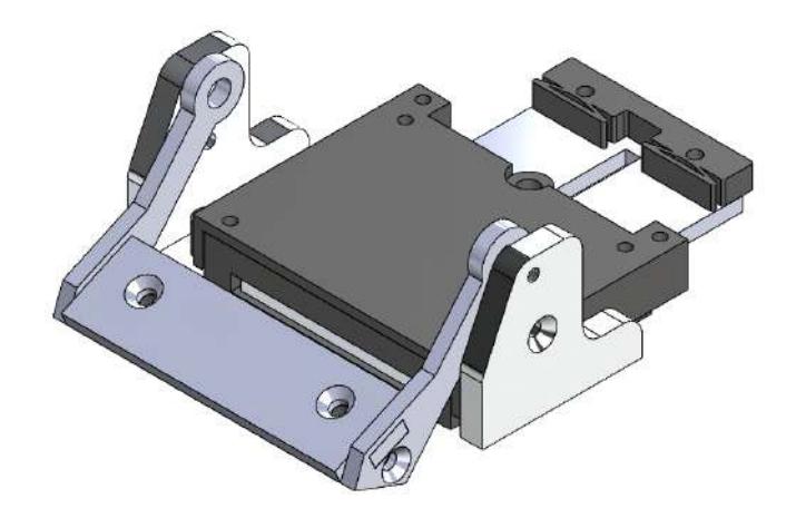
The chipper design is shown in Figure 6. The front surface and arms of the chipper were waterjetted with steel and the base of the chipper was 3D printed using PETG. The metal parts of the chipper were connected with screws to captive nuts in the printed base. The goal of this design was to make the chipper easy to manufacture without sacrificing durability and keeping it lightweight. From initial testing, the chipping distance improved to 230cm on average.
The challenge with this design was shifting the chipper solenoid low enough so that the plunger could directly hit the back of the chipper. To accomplish this, the solenoid was designed to be slimmer with a flat rectangular shape. A cutout in the base plate was made so that the solenoid could sit within the base plate just above the ground itself. A PLA 3D printed solenoid housing secures the solenoid to the base plate from the top. The solenoid plunger was also modified to have a smaller profile and reduce the size of the cutout in the base plate by integrating the return mechanism inside the plunger. The return spring is fitted in a slot in the plunger and hooked to the plunger at the front. The end of the spring is connected through a screw at the back of the solenoid. A TPU damper is installed at the back of the plunger to reduce the impact.
Chassis
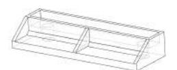
At RoboCup 2023, our team noticed that our robots occasionally changed direction suddenly and unexpectedly. After reviewing gameplay and test footage, it was determined that the front wheels on the robots sometimes lose contact with the ground, especially while accelerating. A simple fix to this problem was to lower the center of gravity of the robots to reduce wheel slippage, and thus reduce the likelihood of sudden trajectory changes while accelerating. 3D printed risers as seen in Figure 7 have been added to the 2024 fleet of robots to lower the overall center of gravity. The PETG risers are installed under the motor mounts behind each wheel, lowering the robot by 4 mm. The risers were also designed with an extended base behind the motor mounts to better support the wheel assemblies during gameplay. Changes were not made to the motor mounts directly as their manufacturing cost was very high - adding risers seemed to be more efficient.
Further Action
While the risers were an apt solution to the robots not driving straight, we are still investigating this issue. The wheel modules our team is currently using have been a part of our robot since 2020 - many have worn out due to wear and tear. As a result, some parts made of weaker materials have undergone misalignment and bending. These minor shifts add up and may have been the primary cause of the robots' misaligned movement. Aside from the fixed height for the wheel risers, we added washers of different heights underneath the motormounts as necessary to align them - running the square path test using the GUI diagnostics tool showed that the washers improved the motion greatly and thus confirmed our issue.
Electrical
Electrical System Overview
This year's general electrical stackup did not change from last year. We fixed bugs that plagued us in Robocup 2021 and 2022, and implemented new quality of life improvements to automate robot testing. We also recognized some shortcomings in our current electrical design and began a multi-year effort to overhaul the motordriver board, find a Jetson Nano replacement, develop a robust radio solution, and more.
Power Board
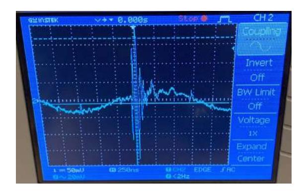
In 2022 and 2023, when the power board would kick or chip, the Jetson Nano and/or Motordriver board would reset, causing our robot to lose control of the motors. After taking some measurements on PGND (noisy ground housing HV regulation, IGBTs, etc.) and 5V with GND (quiet GND housing ESP32, communication circuitry, etc.) during a kick, we produced Figure 8. These lines show significant ringing during a kick (as much as +/-4.8V on PGND). Note here that due to the long length of the probe's ground wire during the measurement, this likely resulted in amplification of the measured ringing, and in reality the ringing was likely not as large (or else we would have noticed the Jetson Nano and other circuits being damaged).
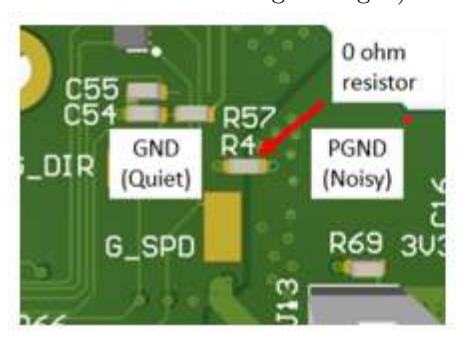
To solve this issue, last year we primarily looked into galvanic isolation between the HV side and the LV side, but due to the cost, complexity, and board space required to implement full isolation, the team went in a different direction.
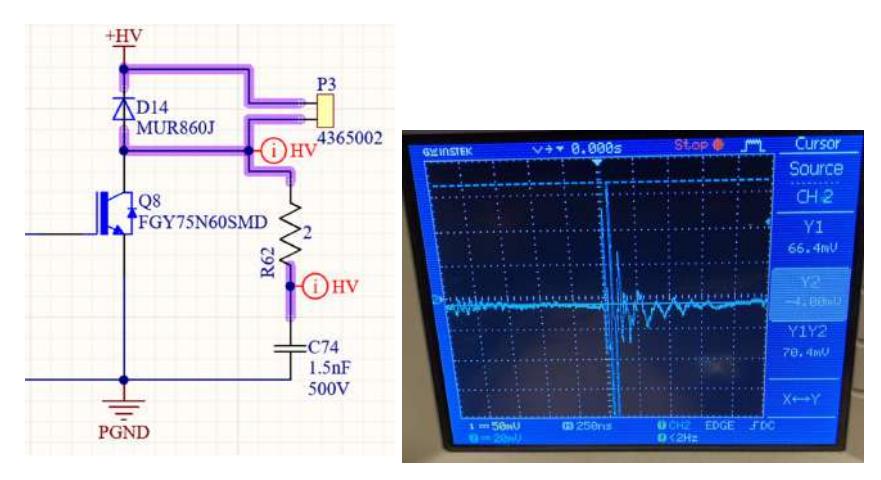
Instead of trying to contain the ringing in a localized area, as we would have done with isolation, the team decided to damp the ringing at the source by adding an RC snubber across the IGBT collector-emitter, as shown in Figure 11. The addition of the untuned snubber allowed us to kick weakly without resetting, but would reset at higher kick strengths. We then slowly increased the capacitance of the snubber so that more of the ringing energy is dissipated, resulting in lower ringing amplitude. At a snubber value of 1Ω and 1nF, the robot was able to kick at max strength without resetting, so we added a 1.5x safety factor to account for robot-to-robot assembly differences. With the snubber added, the PGND and 5V lines were measured again, as shown in Figure 10, and the ringing amplitude was reduced to 80mV in the case of the 5V line, a 60x reduction.
Motor Driver Board
The motor driver board is undergoing a two-year redesign towards a solution that is simpler to implement and easier to maintain in a student design team setting. Our current motor driver PCB uses Trinamic controllers and drivers, which come in 76-pin QFN packages that are difficult to solder manually and debug. Furthermore, we seek a motor driver IC that integrates the controller and driver into one package to mitigate the PCB complexity and streamline the design process. We will also reroute the SPI buses to increase the communication speed from 2MHz to 10MHz. This redesign will be a helpful case study for other teams in the league aiming for a combined controller-driver architecture to simplify their motor driver PCB design.
We identified STM's STSPIN32F025x (STSPIN) IC family as the most promising integrated motor driver solution for our needs. The STSPIN chip embeds an STM32 MCU and a gate driver within one package, reducing board size. The available QFP package with exposed leads eases the soldering and debugging process for new design team members. STSPIN also implements FOC for excellent motor control. After working with the chip's evaluation board (STM's EVSPIN32) to validate the motor driver and fine-tune the control parameters, the team is designing a custom PCB solution for our robots using the STSPIN chips. On the firmware side, we are utilizing the STSPIN motor control library with SPI to communicate between the Jetson Nano and the motor driver board. Furthermore, we are considering implementing a custom command interface to tailor commands to our needs.
Radio Board
When using Wi-Fi during competition, complications such as network congestion and bandwidth interruption could possibly occur. In the past, we used NRF radio chips but their limited payload byte size and power supply stability issues caused significant packet loss, making them extremely unreliable in competition. To address this issue, the team is investigating using the E28-2G4M12S which is designed based on the SX1280 module. The E28-2G4M12S will allow the team to utilize the LoRa protocol and communicate with the robots during competition. The team aims to reduce packet loss significantly (to avoid the need for ACKs) and add support of multicasting messages to all robots simultaneously. The latency which includes queuing and transmission for the AI computer and the latency for receiving the message for six robots will be parallelized in this new architecture which will significantly reduce latency. We are aiming for this radio solution to provide a reliable backup in case of Wi-Fi complications at Robocup.
Breakbeam Board
Version 1 of the Breakbeam (BKBM V1) board was introduced in our 2023 TDP to enhance the reliability of our ball detection capabilities, however, the RoboCup 2023 competition revealed that the IR LED connections were shearing off during a head-on collision. Consequently, the robots incorrectly perceived the IR beam as broken, leading them to believe they had control of the ball. Unfortunately, our software could not address this issue, causing our robots to remain stationary in the middle of the field.
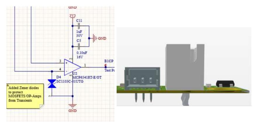
In response to the challenges faced during RoboCup 2023, BKBM V1.1 was developed with several modifications to minimize the risk of recurring failures:
- Introduced a GPIO from the control board to detect cable shearing.
- Replaced cable headers with through-hole connectors for a lower profile.
- Incorporated Zener diodes to safeguard logic circuits from static electricity generated by vibrations in the dribbler assembly.
Linux Computer Research
Over the past few years, we have used Nvidia's Jetson Nano Dev Kit, being an excellent computer for most processes, including robot control algorithms and serial communication across the hardware. However, as Nvidia has stopped its production, prices haven been rapidly increasing for the Nano's, and there is a risk of not being able to obtain any new ones in the future, if the stock continues to decrease. The Jetson Nano also had some disadvantages like a timer which limited the communication between software on the computer, and the hardware of the robots, leading to a high input delay. Additionally, the Nano is now outdated and several alternatives have a higher computing power, which could ultimately lead to more successful competition. For those reasons, we have decided to upgrade all Jetson Nano's to the newest Raspberry Pi 5 which runs on the same CPU architecture as the Nano but has a three times higher expected performance. This does not only help us to reduce the flaws from the Nano, but will also equip us with the newest high-tech in the industry for robotics.
Software
All our software and firmware is open-source, and is available from our git repository: https://github.com/UBC-Thunderbots/Software.
Robot Software
Due to our transition to Linux-based Jetson Nanos in 2022, our firmware architecture required a full redesign. Our previous architecture, as outlined in our 2014 TDP, involved using an ARM-based STM32F4 running FreeRTOS with a GCC compiler. However, the Jetson Nano offered us the chance to share a common software stack with our C++ gameplay software, simplifying the complexity of software written for the robots and encouraging more contributors on a student design team with limited experience. Furthermore, we could use built-in Linux abstractions to simplify hardware interactions, using libraries such as spidev for communication over SPI to the motor driver. Finally, we can leverage a large number of open-source tooling to simplify robot configuration and robot fleet management. Below, a subset of tools are described:
systemd: firmware persistence at any cost Systemd is a system and service manager built-in to most Linux distributions. By setting up our main loop as a system service, we ensure that any errors or crashes during gameplay will be restarted by systemd and in the event of a full power loss, the operating system will automatically start after reboot. Systemd can handle the initialization of certain services that our code depends on, such as the initialization of a WiFi internet connection through Linux's NetworkManager, and simplifying our written control logic.
Redis: robot-specific configuration REDIS is a powerful, open-source in-memory key-value store. Robot-specific configurations such as robot IDs and calibration constants for the kicker and chipper are stored within REDIS.
Ansible: fleet deployment Ansible is an IT automation tool specializing in deployment to remote devices through SSH. By creating "playbooks", Thunderbots has simplified the process of deploying robot software to one or more robots and standardizing robot setup and flashing across its entire fleet through a single command.
We have written playbooks for:
- Compiling robot software and flashing it onto the Jetson Nano as a systemd service
- Create custom robot diagnostics tests for various electrical and motor components
- Updating firmware on the robot itself
New Trajectory Planner
Motivation In our 2023 TDP we proposed a new motion planning architecture which used the ENLSVG path planner coupled with the HRVO algorithm for local obstacle avoidance, to replace our old path planner, Theta*. This was achieved by incorporating the ENLSVG path planner into our AI and the HRVO obstacle avoidance algorithm onto each robot's Jetson Nano. Our main goals with this new architecture consisted of improving the runtime performance of our AI while allowing the robots to be more responsive to their environment by locally simulating the evolving state of the world.
The old motion planning architecture (ENLSVG with HRVO), although functional, had several drawbacks which were initially overlooked and impeded the robot's performance. Firstly, the ENLSVG path planner, similar to many other common path planning algorithms, generated paths which did not take into account the robot's kinematic constraints. This often resulted in robots deviating off of computed paths, and in the worst cases, colliding with other robots. Secondly, the HRVO velocity planner was slow to navigate around obstacles close to the robot it was running on. This was due to the objective being to minimize the distance to the destination point, which led to incredibly slow lateral movement around obstacles.
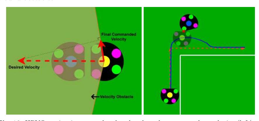
Another limitation was that obstacle avoidance was performed only based on the current state of the world, and did not take into account the future state of the world including where the robot might end up. This led to cases where the robot could not navigate around a wall of enemy robots to a destination on the other side, as it would attempt to navigate through the wall and either collide, or come to a halt. Various solutions were attempted to overcome this limitation of the algorithm, however, most of which resulted in a reduced obstacle avoidance accuracy.
One other reason we considered moving away from ENLSVG was due to the code's complexity which made it difficult to maintain and extend. There were simple bugs that could only be fixed through a major refactor of the library code, which was often written in a non-maintainable fashion. When switching to the HRVO planner, we faced the same problem, yet this time we attempted to refactor most of the code in order for it to be more readable and extendable. Unfortunately, there were some areas that still needed major work, and it was decided to switch to a simpler and more maintainable system for future software members.
These fundamental limitations of our architecture led us to rethink our approach and establish clear requirements for a new design. These included:
- Elimination of grid representation of the field and obstacles in favour of planning over a continuous space for more precise collision detection and reduced overhead of computing the blocked grid cells.
- Integration of other robots' velocities and trajectories into trajectory evaluation.
- Improved modelling of robot's motion by considering its kinematic constraints.
- Optimizing for minimum time to destination as opposed to minimum distance travelled.
After investigating various different solutions, we believe that adopting a trajectory planner, akin to the Bang Bang Trajectory Planner proposed in TIGERs Mannheim's 2019 TDP, will address these requirements and enhance our robots' performance in the dynamic and competitive environment of Robocup SSL. Furthermore, trajectory planners have been utilized by multiple teams in the SSL league with great results which solidified our decision to move in this direction.
New Architecture Our trajectory planner implementation is written in C++. In our new architecture, our AI computer runs an instance of the trajectory planner per robot which returns the best sampled trajectory every tick, which is then sent to the robots. Given that we have Jetson Nanos on our robots that also run C++ binaries, the trajectory type information is shared between the AI and the robot software. This allows us to send a list of trajectory parameters to the robots, so the robots can reconstruct the best trajectory locally, and step through it to generate the velocity commands at a higher frequency than our AI. The parameters used to generate the trajectory are serialized using Protocol Buffers and communicated over WiFi to each robot.
Next Steps With the robots not simulating the current state of the world using the HRVO algorithm anymore, we have been able to significantly reduce the communication bandwidth required between our AI and robots from ∼1500 bytes per AI step per robot to <100 bytes. Given the reduced required bandwidth, our team is planning to perform additional tests comparing communication over radio with WiFi.
Automated Field Testing
In our 2023 TDP, we mentioned our efforts to develop a continuous integration automated test suite for AI behavior to prevent regression. We also mentioned being able to replay a previous simulation to analyze AI decisions with a PyQtGraph based framework, which has served us well to determine the root cause of unwanted AI behaviors. However, there were still two gaps which needed to be addressed:
- Flaky AI tests, which led to unreliable regression testing
- Difficulty in replicating a simulated test with real robots
To address the first issue, we developed an aggregate testing framework for tests involving high-level AI behavior for which exact, discrete validation could not be made. Through this, tests are run multiple times and their results are aggregated. They are then compared to a pre-determined threshold which ensures AI quality while leaving room for non-determinism, making our regression tests more reliable and more accurate.
To address the second issue, we developed a field testing framework, which lets us execute a pre-determined situation using real robots on the field instead of simulated ones. This extends our existing PyTest testing framework, making it easy to generate new reproducible testing scenarios or port over existing simulated tests to the real world. Being able to test and compare our motion planning frameworks outside of simulation has significantly helped with the tuning and the verification time needed.
Driving Straight During the testing stages for HRVO algorithm and Bang Bang Trajectories, we found that having both an easy-to-use diagnostic tool and a general physical testing framework has allowed for improved analysis of the robots and better triaging of issues among the entire team. In particular, Thunderscope includes a GUI diagnostics tool that allows for testing linear and rotational movement of the robot. The tool transforms velocity vector inputs into individual motor controls, which allows testers to isolate physical issues with the robot from software issues and tuning issues derived from high-level motion planning. Additionally, using the field test framework, a common test that we have frequently performed is to have the robot drive along a square path while facing the same direction relative to the field, in order to test each axis of movement (forward, backward, and side-to-side). This allowed us to further diagnose and tune the motion planning frameworks, as well as compare the individual physical robot movement for further diagnosis.
Lane-Based Defense
We implemented a new defense strategy capable of breaking up passing plays involving multiple opponent robots. The strategy first identifies threats that describe the positions of enemy robots; then, it determines open lanes between threats and the goal that represent possible shooting or passing options the enemy team can take. The lane geometry is used to generate defensive assignments describing locations on the field a defender could target to block a potential enemy pass or shot on goal.
An advantage of a lane-based positioning algorithm for defenders is that nearcollinear and neighbouring lanes can be grouped together and be treated as a single lane. The concept is based on the defense system described in TIGERs Mannheim's 2017 TDP, which groups together clusters of robots with a similar angle to the goal. Blocking a lane group representing the sightline of multiple enemy robots requires only a single defender; this frees up the number of available defenders to cover other lanes and creates a more balanced defensive coverage against the attacking team. Defenders can also be positioned at the intersection of multiple lanes, enabling a single defender to block both a shooting lane and passing lane simultaneously.
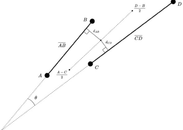
Lane groups are determined by comparing each lane with each other for approximate collinearity. Two lanes modelled by line segments AB and CD are considered near-collinear if the convex angle between them is less than a threshold α and if the shortest distance from each lane to the midpoint of the two lanes averaged together is less than a threshold β. The resultant line segment representing a lane group is produced by averaging together the group's constituent lanes.
Conclusion
We believe that the design changes detailed above will lead to significant improvements in performance. We look forward to implementing these designs at RoboCup 2024.
Acknowledgements
We would like to thank our sponsors as well as the University of British Columbia, namely the Faculty of Applied Science and the departments of Math, Mechanical Engineering, Electrical and Computer Engineering, Integrated Engineering, Manufacturing Engineering, and Materials Engineering. Without their support, developing our robots and competing at RoboCup would not be possible.
Additionally, we appreciate the efforts of Nicolai Ommer in fulfilling our request for the AutoRef asynchronous interface and his ongoing support in getting the communication setup. We have successfully integrated the Autoref into our automated regression pipeline and Ommer's work has helped us uncover several bugs early.
References
- A. Senthilkumar, A. Sidhu, A. Balamurali, D. Sturn, D. Antoniuk, D. To, F. Muhstaq, F. Crema, H. Bryant, H. Rovner, J. Lew, K. Wakaba, N. Zareian, O. Levy, R. Khan, R. Cao, R. Nedjabat, T. Kong, S. Ajmal, S. Ly, and Y. Zhou, "2023 Team Description Paper: UBC Thunderbots," 2023.
- P. Dumitru, G. Ellis, J. Fink, B. Hers, J. Lew, M. MacDougall, E. Morcom, S. H., C. Sousa, W. Van Dam, G. Whyte, L. Zhang, S. Zheng, and Y. Zhou, "2020 Team Description Paper: UBC Thunderbots," 2020.
- A. Almoallim, C. Sousa, D. Sturn, D. Antoniuk, F. Crema, H. Bryant, J. Lew, J. Liu, K. Wakaba, L. Bontkes, and Y. Zhou, "2022 Team Description Paper: UBC Thunderbots," 2022.
- J. Fraser, S. Ghosh, C. Head, S. Holdjik, N. Jaques, A. Lam, B. Wang, A. Wong, and K. Yu, "2014 Team Description Paper: UBC Thunderbots," 2014.
- Linux Kernel Organization, Inc., "Spidev Documentation."
- systemd, "System and Service Manager."
- Redis Ltd., "Redis."
- Red Hat, Inc., "Ansible."
- S. Oh and H. Leong, "Edge n-level sparse visibility graphs: Fast optimal any-angle pathfinding using hierarchical taut path," 2017.
- J. Snape, J. v. d. Berg, S. J. Guy, and D. Manocha, "The hybrid reciprocal velocity obstacle," IEEE Transactions on Robotics, vol. 27, 2011.
- N. Ommer, A. Ryll, and M. Geiger, "Extended Team Description for RoboCup 2019," 2019.
- A. R. N. O. D. E. F. B. Mark Geiger, Chris Carstensen, "Extended team description for robocup 2017," 2017.