First Order Robotics Team Description Paper Small Size League of RoboCup 2025
Martin Liang, Joel Ng, Fred Huang, Louis Yong, Pi Rong Koh, Hamish Starling, Luke Moran
Imperial College London, Exhibition Rd, South Kensington, London, UK
Abstract This paper describes the efforts and improvements made by the First Order Robotics Team to compete in the 2025 RoboCup Small Size League Division B. It describes the major hardware improvements from the previous year's design, along with a newly developed codebase for the control and coordination of the robots.
1 Introduction
The First Order Robotics Team is a newly formed student-run group from Imperial College London under the umbrella of the Imperial College Robotics Society (ICRS). Initially formed under ICRS FC in 2023, the team was unsuccessful in qualifying, as it struggled with lacklustre student engagement, along with a plethora of mechanical, hardware and software roadblocks. This year, the team has seen a significant reconsolidation of its members' effort to design a credible hardware system and codebase by studying ETDPs and TDPs from successful teams, and learning from the team's past mistakes in 2024. This year, the team has also enjoyed a revitalized software development team that has made substantial progress in the robotic control and coordination algorithm design, as detailed in Section 5. This paper is divided into four major categories: mechanical systems, hardware, embedded systems and software.
2 Mechanical Systems
(heading paragraph)
2.1 Objectives
Last year was our first attempt at designing and building robots that fit the RoboCup SSL competition criteria. The previous generation used a three-wheel omnidirectional layout with a simple fixed-frame dribbler design. The kicker employed a spring-loaded mechanism.
Looking back, many of these design decisions were not ideal. For example, the threewheel layout significantly restricted the dribbler module's open-for-catch size when receiving the ball. Another issue was that the chosen motor had a relatively long body extending toward the wheelbase center, severely limiting the available space for the solenoid, restricting shooting performance, and leaving no room for future upgrades. Only two units were produced last year. The design from last year can be seen in Figure 1 (1) and (2).
This year, our goal is to redesign from first principles, correct past mistakes, make well-informed engineering decisions for mass production, and ensure expandability for future iterations in the coming years. As a new team, we aim to achieve top-tier mechanical performance in Division B and ultimately reach a level where we are competitive with Division A teams.
The final design of the robot for SSL this year is shown in figure 1 (3)-(6), with details discussed below.
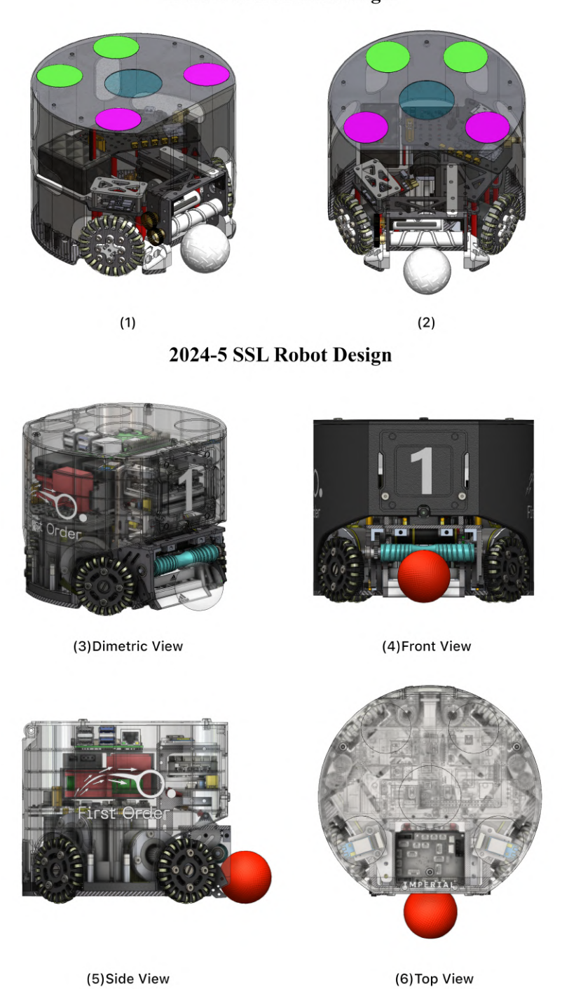
2.2 Wheelbase
The wheelbase defines the overall framework of the mechatronic system, and the design of each wheel actuator unit directly determines the available design space for other modules. Therefore, it is made as compact as possible while ensuring sufficient clearance for the dribbler and kicker at the front and middle, respectively.
In our final design, each wheel actuator unit comprises a motor secured to a carbon fibre base using a CNC-machined aluminium alloy block, with a 3D-printed plastic spacer in between for reinforcement. This structure ensures rigidity and prevents yielding or bending. The CNC block is an off-the-shelf standard component with prethreaded mounting points, offering ease of assembly and cost efficiency. The assembled design is shown in figure 2.
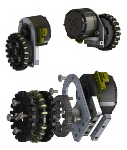
Table 1. DM3519 Motor Specifications
| DM3519 Motor Parameters | |
|---|---|
| Rated Voltage | 24V (Drive supports 15-52V supply) |
| Rated Phase Current (Power Supply Current) | 9.2A (8.6A) |
| Peak Phase Current (Bus Current) | 20.5A (16.1A) |
| Rated Torque | 3.5Nm |
| Peak Torque | 7.8Nm |
| Rated Speed | 395rpm |
| No-load Maximum Speed | 435rpm |
With this crucial component finalized, the design space for other modules was established. The whole robot assembly breakdown is shown in Figure 3, with important specifications listed in Table 2.
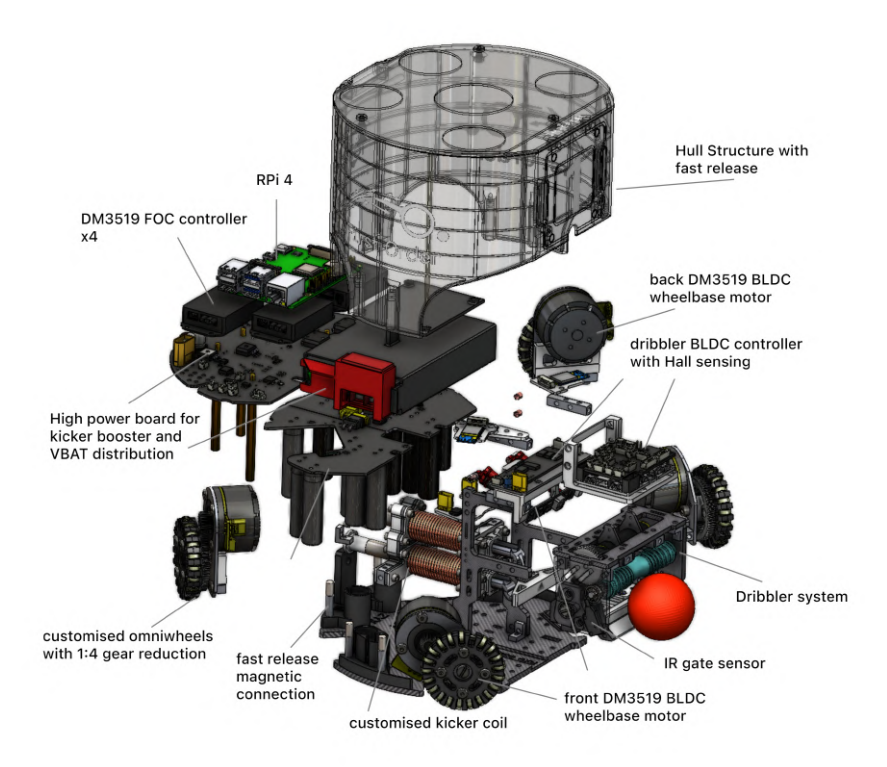
Table 2. Essential Physical Specifications
| Specification | Value |
|---|---|
| Ball Exposure Area Percentage | 82% |
| Robot Dimension (D x H) | D: 178mm, H: 149mm |
| Wheel Diameter | 53.6mm |
| Power Supply | 6s BAK Li-ion 18650 22.2V 2500mAh |
| Approx Weight | 2.1kg |
2.3 Dribbler System
The dribbler is the most complex mechanical unit in an SSL robot. Based on insights from previous TDPs of other teams, a well-designed dribbler should have the following key features.
- High RPM: Ensures the ball remains in contact with the rod both at rest and during motion.
- Shock Absorption: Effectively dampens impact when the ball enters the dribbler at high speed.
- Self-Centering Capability: Improves precision shooting and enables the robot to execute sharper turns with higher angular velocity.
Due to budget limitations, we were unable to source for a dribbler motor with similar specifications (>35W, 20K+ RPM) as described in other papers [11]. To minimize design limitations, we selected a 12W BLDC motor with a built-in Hall sensor and a speed of over 12K RPM, originally designed for surgical applications (e.g., plaster removal). The actual performance of this motor is still under evaluation, but based on initial observations, it performs satisfactorily.
Recognizing that the motor speed of the dribbler is crucial for ball control, we designed a ball feed-in status feedback mechanism to enable closed-loop control.
2.3.1 Design Considerations & Mechanisms
We studied the dribbler designs of teams such as ZJUNLICT [3] and TIGER [4], implementing a single DoF rotational mechanism for our dribbler. Additionally, a spring-damper system, commonly used in RC car models for shock absorption, was installed between the dribbler rotor frame and the wheelbase. The spring constantly pushes the dribbler rod forward, and when the ball enters, the compression of the spring and damping oil counteract the shock impact. Both the spring and damping oil are replaceable, allowing us to test different damping levels and spring constants.
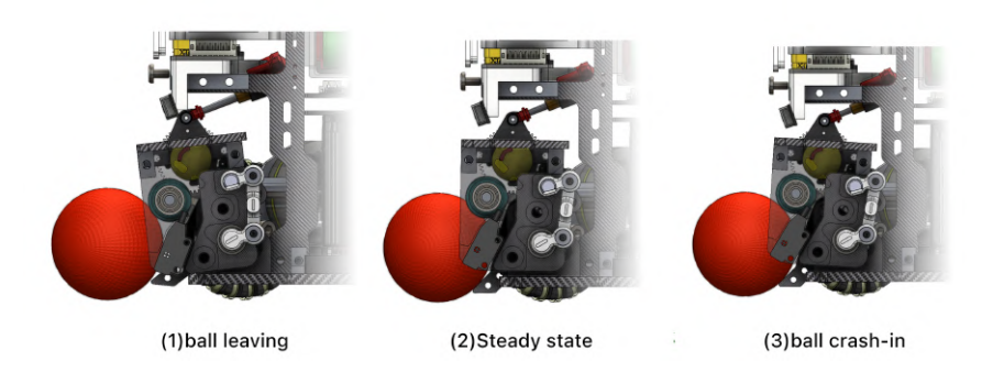
A parallelogram linkage is constructed within the dribbler, with one side fixed to a stationary screw and the other attached to an incremental rotary encoder. This synchronizes rotary motion and provides angle feedback. The system informs the robot of the ball's behaviour — whether it is feeding in, leaving the rod, or bouncing against it. This feedback can dynamically adjust the dribbler speed, ensuring precise control. A visual illustration is shown in Figure 4.
2.4 Kicker Actuation
The kicker of the robot, although designed and manufactured, has not been thoroughly tested due to the unfinished control board. The primary goal is to maximize the kicking speed.
From a research paper from Eastern Washington University [14], we know that the force generated by a solenoid is proportional to certain key parameters, as shown in the equation below. A simple conclusion can be drawn: winding factor and internal resistance are crucial in solenoid coil design. A solenoid with thin wire and a high turn count is less desirable than one with thicker wire and fewer turns if the resistance is too high.
$$F = \frac{-V^2 \mu_r \mu_0}{8\pi \left(\frac{\rho}{a}\right)^2 l^2} \left(\frac{r_0}{\frac{a}{2\lambda l}N + r_0}\right)^2 \alpha e^{-\frac{\alpha}{l}x}$$
Where ρ is the resistivity of the material, a is the cross-sectional area of the wire, l is the coil length, µ₀ and µᵣ are permittivity, V is the applied voltage, N is the number of windings, r₀ is the internal radius of the coil.
Additionally, the plunger material must have high magnetic permeability and high saturation flux density to ensure optimal performance. According to previous studies, 1020 steel is a suitable material for this application. However, after further research, we found that DT4 is also a viable alternative. DT4 is also readily available, easy to manufacture, and cost-effective. A comparison between DT4 and 1020 steel is provided in Table 3.
Table 3. Comparison of 1020 Steel and DT4 Material for Solenoid Plungers
| Property | 1020 Steel | DT4 (Soft Magnetic Alloy) |
|---|---|---|
| Composition | Low-carbon steel (0.18-0.23% C) | High-purity iron |
| Magnetic Permeability | Moderate | High |
| Saturation Flux Density | ≈ 2.1 T | ≈ 2.0 T |
| Coercivity | Higher | Lower |
| Electrical Resistivity | 10⁻⁷ Ω·m | Slightly higher than 1020 steel |
| Machinability | Good | Moderate |
| Corrosion Resistance | Low | Low |
| Cost | Lower | Higher |
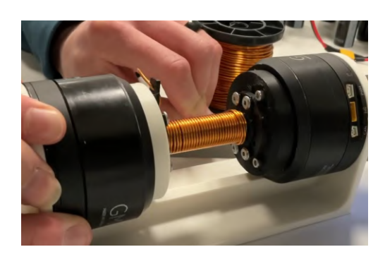
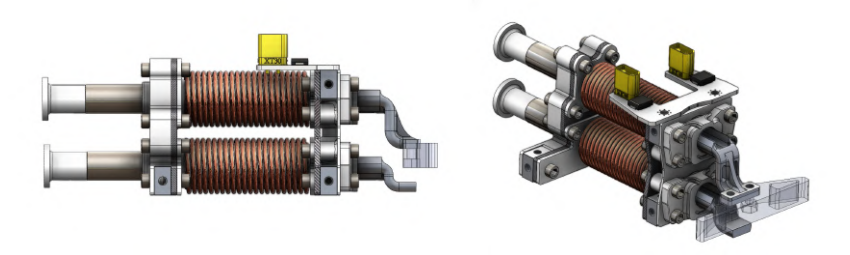
In order to produce the coil with good winding factor in-house, a winding machine was made to facilitate this process, as shown in Figure 5. Additionally, for simpler routing & assembly, the solenoid coil ends are connected to an XT30 ports installed on a PCB. The full model of the kicker is shown in Figure 6, with the upper coil for parallel kicking and lower one for chip kicking. The chip kicking uses a percussion mechanism described in a ZJUNLICT TDP [5]. A preliminary test was done using a boost converter that charges a capacitor array to 90V. This was discharged immediately through a mechanical switch. From the accompanying video submission, the ball can be seen to eject at roughly 3m/s. Please note that in our qualification video, the high-power kicker board responsible for controlling the charging and discharging of the kicking actuation is still under development. As a result, we have used the robot to collide with the ball and push it toward the goal instead. The video of the capacitor array discharge is attached at the end, which should perform effectively the same for our final version [12]. More supplementary media materials will be posted in the future under the same channel.
3 Hardware
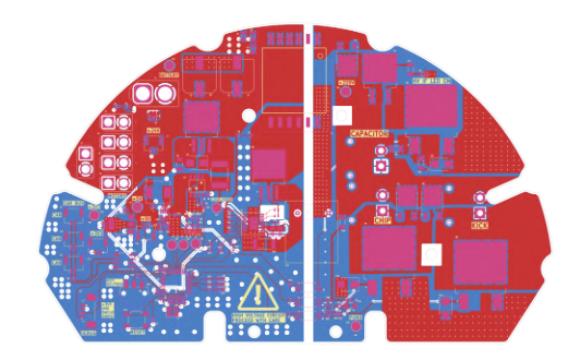
The robot's operation is managed by three primary boards: the main control board, the kicker board, and a Raspberry Pi. The main control board communicates with the central computer via the onboard NRF24 module, controls five BLDC motors (four for movement and one for dribbling), and processes inputs from various sensors, including infrared sensors, encoders, and a compass. The kicker board is responsible for distributing power across the robot's voltage rails (24V, 5V, and 3.3V) and supplying power to the two kicking solenoids. Finally, the Raspberry Pi is dedicated to handling the camera, which provides additional data to enhance the robot's decision-making capabilities.
3.1 Main Control Board
In this year's iteration, a robotics specific STM32H723VGT6 development board is used for the following reasons:
- The DM-MC02 STM32H723VGT6 development board can be procured at a decent price with very compact physical dimensions.
- The board comes with most of the peripherals needed, such as USART, SPI, CAN ports, saving manpower and costs related to prototyping.
However, a key limitation of this approach is the insufficient number of GPIO pins to meet the robot's requirements. To address this constraint, an additional extension board was designed and stacked above the main board, utilizing the extension BTB port for expanded functionality. Future development will focus on developing a new hardware unit with same MCU that server as a role of a master transmitter, which communicates between the main decision-making PC and all 6 robots in the field. This board will have features such as a screen and buttons for debugging and status input, and multiple NRF24 and antennas installed.
3.2 Kicker Board
In the previous year, challenges arose in the design of the robot's kicker due to the use of relays for discharging the capacitor bank. Over time, the relay contacts experienced wear and tear, leading to reliability issues. In the current iteration, power MOSFETs have been implemented as a more reliable alternative, ensuring faster and more consistent discharge performance.
3.2.1 Capacitor Array
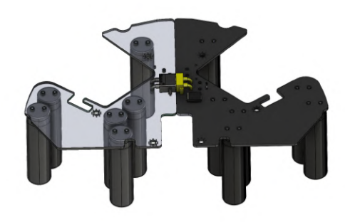
The kicker is powered by a capacitor bank consisting of 12 265uF 330V electrolytic capacitors connected in parallel. This configuration provides a theoretical maximum energy of 173J. However, the capacitors are only charged up to 120V, as this voltage is sufficient to propel the ball at the speed limit of 6.5m/s.
3.2.2 Charging Architecture
The capacitor bank is charged using the LT3751 high voltage capacitor charger. This chip enables rapid charging, allowing the capacitor bank to fully charge in under 2 seconds, ensuring minimal downtime between kicks. This is a huge improvement from last year's charging time, allowing for higher frequency of passes and an improved strategy.
3.2.3 Safety and Isolation
Given the high voltages involved, the kicker board is designed with safety in mind to protect the user:
- Galvanic Isolation: The board is divided into low and high-voltage sections, which are galvanically isolated to protect the MCUs. Transformers handle power delivery, while optocouplers transmit digital signals. This isolation has proven effective in safeguarding the low power control system, especially during high-power testing.
- Automatic Discharge: To prevent accidental shocks, the capacitor bank automatically discharges through a power resistor when the battery is disconnected.
One limitation of the current design is that the kicker's strength cannot be easily adjusted due to galvanic isolation. Future iterations will incorporate a variable voltage charging mechanism, allowing for adjustable kick strength and greater strategic flexibility in gameplay.
3.3 Wireless Communication
Last year, we selected the NRF24L01 as the RF solution for communication between the controller PC and each bot. A PCB was designed with this chip and its peripherals, with signals output through an on-board PCB antenna. This setup has proven effective, and we continue to use this model this year. Two improvements have been proposed.
- To enhance transmission stability and ensure a secure connection, each NRF24 module is now decoupled from the main control PCB and installed in a dedicated area, making it easier to replace if damaged. Additionally, each module is equipped with a power amplifier, low-noise amplifier, and an SMA antenna connected via an IPEX coaxial cable.
- Each robot is now equipped with two NRF24 modules, with one dedicated solely to receiving (Rx) and the other to transmitting (Tx). This allows for greater communication bandwidth. Although considerable redundancy is reserved for current software development, this setup ensures sufficient data transfer bandwidth in the future.
3.4 Raspberry Pi
Each bot is equipped with a Raspberry Pi 4 that serves as a reserve on-board computing platform with wireless connectivity. While software development is still in progress, it will eventually support high-computing tasks, such as edge ML and vision processing, that the STM32H7 cannot handle. The following functions are proposed for development.
- Robot Status Broadcasting: The Raspberry Pi connects the H7 and Kicker (high power) board via the UART protocol, receiving utility data such as real-time power consumption, computational resource usage, and system logs. This information can be broadcasted over the on-board Wi-Fi to a central server for remote monitoring.
- On-device MCU Firmware Downloader/Debugger: Our current toolchain involves using STM32CubeMX to generate the necessary driver code for the H7 board, followed by compiling the code into firmware using makefile, and then flashing it onto the MCU via ST-Link. This process can be tedious, especially when tuning the robots in motion. With a Raspberry Pi on the bot, we can use it as a Linux platform to modify, compile, and wirelessly connect to the MCU for flashing, offering significant convenience.
- Vision Processing: An HD 30 FPS USB camera, mounted on top of the dribbler, serves as the only on-device perception sensor for each bot (apart form the IR gate sensor). Compared to the top global camera, this provides lower latency and eliminates reliance on the master PC for tasks like ball detection [13], autoaiming/catching, self-ball centering, and in the future for collision avoidance, and FPV recording for AI training. These features require an on-board device such as a Raspberry Pi.
4 Embedded Systems
(heading paragraph)
4.1 Movement
Unlike traditional wheeled robots which can only perform translational and nonstationary rotational movement, our robot has 4 omnidirectional wheels located roughly equidistant around the circumference of the robot. This enables simultaneous translational and rotational movement. Prior research on the simultaneous translation and rotation of omniwheeled robots has been done by decomposing the overall movement into individual velocity components for each wheel, parallel to the direction of the wheels [9]. However, an additional velocity component must also be added to each wheel, proportional to the radius of the robot.
4.2 Communications
As mentioned previously in the hardware section, we used the NRF24 module with the STM32H7 board to enable rapid communication between the team controller and robots. The NRF24, a low-cost IC operating in the 2.4GHz ISM band, supports the Enhanced ShockBurst™ (ESB) protocol, which automates packet assembly, acknowledgment, and retransmission to ensure fast, low-latency data transfer.
Furthermore, to minimise latency, we developed a custom message protocol which encapsulates all the possible data which is needed for operation of the team controller and individual robots. The message protocol is designed to be as succinct as possible to minimise the latency involved in transmission and processing the individual data fields in the overall message. The schematic for our protocol is shown in the table below:
- Local Forward Velocity is a 16-bit signed floating point for m/s
- Local Left Velocity is a 16-bit signed floating point for m/s
- Angular Velocity is a 16-bit signed floating point for deg/s
Table 4. Custom Instruction Protocol
| Bits | Description |
|---|---|
| 0 - 15 | Function Local Forward Velocity |
| 16 - 31 | Local Left Velocity |
| 32 - 47 | Angular Velocity |
| 48 | KB (Kicker Bottom) - Boolean |
| 49 | KT (Kicker Top) - Boolean |
| 50 | DB (Dribbler) - Boolean |
| 51 - 55 | Robot ID - 5-bit unsigned integer (0 to 31) |
| 56 - 63 | Spare |
- KB (Kicker Bottom) is a Boolean
- KT (Kicker Top) is a Boolean
- DB (Dribbler) is a Boolean
- Robot ID is a 5-bit unsigned integer representing the robot IDs. While we only use 6 robots, we provide 5 bits for extra redundancy (0 to 31)
5 Software
We transitioned to Python due to its rapid development time and the team's familiarity with the language, ensuring that all members could contribute effectively. Another key advantage is that Python is an interpreted language, making debugging significantly easier. However, we plan to transition to C++ in the future once we encounter performance limitations due to Python's time complexity constraints.
5.1 Simulated Environments
We continue to use grSim to simulate real-world gameplay as closely as possible while simultaneously developing our physical robots. This approach allows us to mitigate potential delays caused by embedded and mechanical components, ensuring that software development progresses smoothly.
This year, we also incorporated the rSoccer environment framework with rSim running as backend simulator [10]. Designed for reinforcement learning by RoboCin, we found the software to be particularly useful as a lightweight simulation environment for the initial development of specific skills (see Section 5.6.1 for the definition of skill). As rSoccer renders with Pygame, we were able to build further visualisation tools such as geometry overlays on the UI for better insights into errors within our algorithms. Furthermore, unlike grSim, rSim does not require UDP ports, reducing potential networking-related issues during the development process.
5.2 Velocity Calculations & Next Frame Predictions
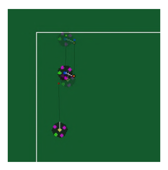
Using the vision data we estimate the velocity of all objects on the field. This is done simply by taking the difference in position between two adjacent frames and dividing by the time between frames (which is assumed to be a constant based on the expected frame rate of 60fps). This information is then used to predict the position of all objects on the field after a fixed period of time for scenarios such as ball blocking by the goalkeeper. This prediction is performed using standard SUVAT equations for the estimated velocity and acceleration, which caps the position when the object is predicted to have stopped.
We also incorporated acceleration estimation for position extrapolation. This proved to be challenging as position noise detected by the camera led to large errors in extrapolation. We therefore performed smoothing in the acceleration calculations by using a sliding window. We take 3 windows of 5 frames, and determine for each window the average velocity of the object under examination. We use this to calculate the acceleration with respect to the previous window, and then average this resulting acceleration across both adjacent window pairs. Testing has showed that this leads to relatively reliable prediction estimations up to a second into the future.
The generally simple approach to these kinematic calculations is preferred as it yields a result which are accurate enough to be useful (especially when used in the simulator), supports quick iteration and testing, and is performant due to being very simple to calculate, as show in Fig 9.
5.3 Queue System
Synchronising all parts of the system while remaining responsive to incoming data packets, avoiding concurrency bugs and keeping the code clean and easy to understand is a challenging aspect of the system design. We opted to tackle this by structuring the system with receivers for the vision and referee data packets running in separate threads. These receivers pass all incoming packets and convert them to an internal message format. These messages are added to a thread-safe queue data structure, which is processed by the main loop. This processing consists of waiting until a message is available on the queue, processing it by updating the game object, and then asking the decision making system for updated robot motion commands which are then sent to the robots. This is repeated in an event loop.
5.4 Game Object
The Game Object serves as a centralized data repository, ensuring consistency and accuracy across all decision-making and strategy processes. By acting as the definitive ground truth for received data, it streamlines access for skills and decision-making algorithms while eliminating inconsistencies in data retrieval.
Beyond storing raw vision data, the Game Object incorporates post-processed information, such as velocity estimations and next-frame predictions. Techniques like Kalman filtering refine vision data by reducing noise and improving tracking accuracy, while extrapolation methods predict robot and ball positions when direct vision data is unavailable. This enhances motion planning and enables more reliable real-time decisions.
A key design goal is to separate decision-making logic from packet processing, ensuring modularity and reducing dependencies on low-level data handling. This structured approach improves code clarity and facilitates continuous enhancements in postprocessing. New tracking and filtering techniques can be integrated seamlessly without disrupting existing strategies, supporting ongoing system improvements.
5.5 Team Controller
The team controller translates the algorithmic decisions to packets for the robots to receive. It also receives and consolidates the responses from the various robots, allowing us to utilise the hardware sensors onboard. We utilise pyserial for two-way UART communication with an external microcontroller, which then communicates with the robots using an NRF24 receiver. The key consideration for this program is speed, where we aim to move over to a low-level package like Boost.Asio to achieve low latency communication with the robots [7].
5.6 Robot Control
(heading paragraph)
5.6.1 Velocity Control
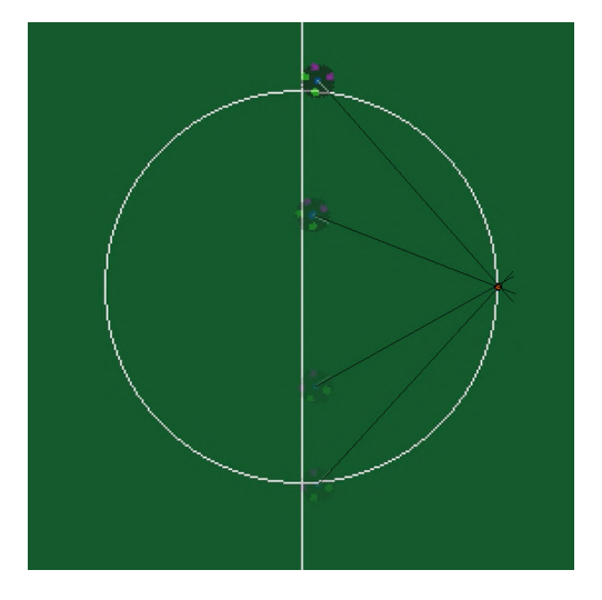
We are currently using a standard PID framework to control the velocity of our robot by providing it with a target location to go to, using three instances of PID: one for orientation, one for x translation, and one for y translation. All three instances are normalised to be between [0,1] to standardise the magnitude between PID instances.
In order to maximise the capabilities of the omnidirectional data, our team implemented a method to offset the translational velocities set by two PIDs with the orientation velocity. This adjustment compensates for the rotational speed during the length of the command, ensuring smoother motion. For instance, when the robot rotates while moving, the translational velocities are dynamically adjusted to maintain the intended trajectory. This enables the robot to be able to continuously track the ball while in motion shown in Fig: 11.
5.6.2 Path Planning
Effective path planning in a dynamic environment is challenging. Our path planning relies on two core ideas. Firstly, the field is relatively sparse, and most obstacles are robots and therefore somewhat transient. Secondly, we require the path planner be performant, where we want to be able to react to obstacles within 1-2 frames. Currently, our implementation is written in Python, which limits the complexity of our path planner. However, if this proves to be problematic, we will re-write it in a lower level language.
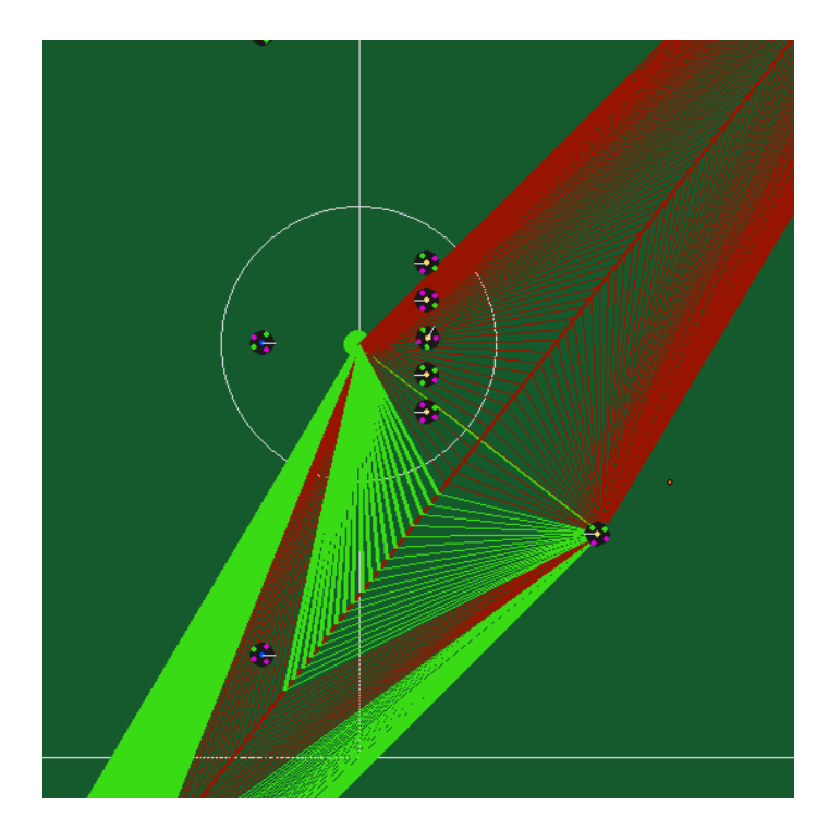
Our path planner consists of two separate planners, each capable of planning in their own right. We combine a Dynamic Window Approach [2] for local planning, with a more computationally expensive bisector algorithm which is used to stop the robot getting stuck in local minima. The original Dynamic Window approach was intended for environments with static obstacles, where viable trajectories are calculated by discounting routes that would lead to collision with obstacles. However, this assumes that obstacles are static and testing showed that approximating our robots and opposition robots as static on a per frame basis did not achieve sufficiently good results as high-velocity robots require a longer time window of awareness in order to adjust trajectories to avoid collisions. Some modifications were needed for this to work in an environment with dynamic obstacles.
Our modified Dynamic Window Approach calculates feasible trajectories according to the robot's kinematic specifications over time steps of 100ms, given the maximum acceleration of the robot, which we assume is uniform in all directions. We sample discrete directions and assume a constant velocity for the robot to project the path of the robot in the next time step as a segment. The segment with the largest score is chosen as the path taken. To score a segment, we consider the distance travelled towards the target and an obstacle factor, which is a function of the obstacle's distance and estimated collision time calculated from the relative velocities. This approach allows us to be reactive to other robots, as collision times greater than the simulated time step are considered as part of the score. This means that we are able to take early evasive action in cases where a collision is expected, whilst maintaining an efficient path when robots are fast-moving but not estimated to collide with us. It also means that the robot slows down when navigating tight spaces, which is desirable to avoid high-speed collisions.
After tuning the weighting functions of the local planner, it is uncommon for it to get stuck in local minima given the sparsity of the field. However, in order to make it more robust to enemy formations such as 2-3 wide walls, we incorporate another planner which produces an intermediate waypoint for the robot to travel to.
We attempted to use an RRT* approach [6], but we found two main issues with it for our use case. The paths generated were not close enough to the optimal paths and had too many turns which slow down the robot. It was not performant enough to generate effective paths in the time-frame that we wanted, and it struggled when the target or start position were very close to obstacles as most segments it attempted to grow would collide immediately.
5.7 Strategy
The strategy we are using is very similar to the STP framework that many other teams currently use [8]. However, we have reshaped some of the definitions to emphasise modularity and consistency.
5.7.1 Skills
Skills are fundamental actions performed by a robot, typically involving one or two robots with minimal coordination. Each skill operates with a primary robot at its core, driving the execution of a specific task. For example, in a passing maneuver, the passing skill is centered on the robot delivering the ball, while the receiving skill runs on the supporting robot to ensure successful reception. Despite involving two robots, this maneuver consists of two distinct skills working in parallel, each focused on its respective role in the action.
5.7.2 Set Plays
Set Plays are a series of coordinated actions involving multiple robots, where the centre of attention shifts dynamically between them. For example, in a sequence where the ball is passed from the wing and then shot at the goal, at least two robots are involved. Initially, the passing robot is the focal point, executing the pass to a supporting robot. Once received, the supporting robot becomes the centre of attention as it attempts to score. This transition represents multiple actions executed in a structured sequence.
5.7.3 Roles
Roles act as containers for a predefined set of actions, grouping tasks based on their relevance and usability in different game states. They range from simple actions like "going to the ball" to complex multi-robot coordination. Assigning roles ensures that each robot has an appropriate set of possible actions. For instance, a goalkeeper would not have "scoring a goal" as an available action, as it contradicts its primary function. Dynamic role assignment allows for strategic adaptability, ensuring robots execute tasks suited to their current responsibilities.
This grouping of actions for each role simplifies decision-making by reducing the complexity of choices the system must process. It also prevents the execution of redundant commands, ensuring that each robot operates efficiently within the specific state of play.
5.8 Decision Maker
Lastly, and most importantly, our decision maker will choose which actions are executed for each robot. This will contain deterministic algorithms like danger maps, evaluating the concentration of enemy robots on the field similar to what Team SRC used in their algorithm for assigning danger ratings of attacking robots to evaluate which robot to block and mark [1].
6 Conclusion
In this paper, we have presented our key hardware improvements aimed at designing a high-performance, cost-effective, and future-proof robotic system. Additionally, we have explored the design of our control and coordination algorithms, emphasizing rapid development and modularity in our codebase to facilitate future enhancements. As a new team, there is still significant room for improvement. Moving forward, the team aims to refine its multi-agent coordination strategy and enhance its motion control systems to maximize stability. We also aim to develop critical hardware integration to leverage the onboard devices such as the camera and accelerometer.
References
- Chen, Z., Pan, S., Wang, Y., Jiang, L., Bao, Y., Peng, J., Tan, Y., Zhu, X.: Src extended team description paper for robocup 2024. RoboCup Soccer Small Size League (2024), https://api.semanticscholar.org/CorpusID:272652231
- Fox, D., Burgard, W., Thrun, S.: The dynamic window approach to collision avoidance. IEEE Robotics & Automation Magazine 4(1), 23–33 (1997). https://doi.org/10.1109/100.580977
- Gao, T., Wu, Y., Yang, T., Huang, Z., Xiong, R.: Zjunlict extended team description paper for robocup 2017 (2017)
- Geiger, M., Ommer, N., Ryll, A.: Robocup 2022 ssl champion tigers mannheim ballcentric dynamic pass-and-score patterns (2022)
- Jin, L., Chen, L., Chen, X., Li, Y., Hu, W., Xiong, R.: Zjunlict extended team description paper for robocup 2016 (2016)
- Karaman, S., Frazzoli, E.: Sampling-based algorithms for optimal motion planning. CoRR abs/1105.1186 (2011), http://arxiv.org/abs/1105.1186
- Kohlhoff, C.M.: Boost.Asio C++ Library (2003–), available at https://www.boost.org/doc/libs/release/doc/html/boost_asio.html
- Lobmeier, C., Burk, D., Wendler, A., Eskofier, B.M.: Er-force 2018 extended team description paper. RoboCup Soccer Small Size League (2018)
- Mariappan, M., Sing, J.C., Wee, C.C., Khoo, B., Wong, W.: Simultaneous rotation and translation movement for four omnidirectional wheels holonomic mobile robot. In: 2014 IEEE International Symposium on Robotics and Manufacturing Automation (ROMA). pp. 69–73 (2014). https://doi.org/10.1109/ROMA.2014.7295864
- Martins, F.B., Machado, M.G., Bassani, H.F., Braga, P.H.M., Barros, E.S.: rsoccer: A framework for studying reinforcement learning in small and very small size robot soccer. In: Alami, R., Biswas, J., Cakmak, M., Obst, O. (eds.) RoboCup 2021: Robot World Cup XXIV. pp. 165–176. Springer International Publishing, Cham (2022)
- Ommer, N., Ryll, A., Ratzel, M., Geiger, M.: Tigers mannheim extended team description for robocup 2024 (2024)
- Robotics, F.O.: First order robotics team ssl25 qualification video (2025), https://youtu.be/RwXMowvYbks
- Ryll, A., Jut, S.: Tigers mannheim extended team description for robocup 2020 (2020)
- Schimpf, P.: A detailed explanation of solenoid force. Int. J. on Recent Trends in Engineering and Technology 8, 25 (2013)