ITAndroids Small Size League Team Description Paper for Robocup 2025
Amadeu Albuquerque Fontenelle Neto, Andrei Freiberger, Arthur Colvet de Souza, Artur Dantas Ferreira da Silva, Bruno Daigo Yamamoto, Joao Pedro Souza dos Santos, Joao Matheus Alves Lima, João Victor dos Santos, Lucas Guimarães Neves, Marcello Ryaj de Almeida Santos, Marcelo Roncato Junior, Marcos R. O. A. Máximo, Mateus Levi Morais Feitosa, Matheus Felipe Ramos Borges, Nando Ferreira Farias, Valerio Augusto Neri da Rocha Barros
Autonomous Computational Systems Lab (LAB-SCA) Aeronautics Institute of Technology (ITA) São José dos Campos, São Paulo, Brazil
Abstract ITAndroids is a robotics competition group associated with the Autonomous Computational Systems Lab (LAB-SCA) at the Aeronautics Institute of Technology (ITA). Over the past year, the team has focused on refining its Small Size League (SSL) robots, introducing substantial improvements across multiple domains. In electronics, efforts were directed toward the development of a new transceiver station to address previous communication issues, as well as the implementation of an infrared sensor to enhance ball detection. Mechanical advancements included a redesigned damping system for better ball control and the increased use of 3D-printed components to improve modularity and reduce costs. On the software side, the team enhanced goal-scoring strategies and refined path-planning algorithms to optimize robot movement. Additionally, significant progress was made in low-level motor control, introducing optimized PI controllers for improved stability and response. This paper presents an overview of our recent advancements, the challenges faced, and our future directions toward RoboCup 2025.
1 Introduction
ITAndroids is a multidisciplinary robotics research group at the Aeronautics Institute of Technology (ITA), with around 20 members actively engaged in the Small Size League (SSL) team. In the past year, we achieved outstanding results in both competitions we participated in, reinforcing our position as a competitive team. Building on this success, we focused on improving communication reliability with a new transceiver station, enhancing ball control with a redesigned damping system, and optimizing modularity through increased use of 3D-printed components.
On the software side, we refined goal-scoring strategies and path-planning algorithms to improve robot decision-making and adaptability. Additionally, advancements in low-level motor control, including optimized PI controllers, have led to more precise and stable motion execution. This paper details these developments and is structured as follows: Section 2 presents our advancements in electronics, focusing on the transceiver station and infrared sensor for ball detection. Section 3 discusses mechanical improvements, including the damping system and 3D-printed components. Section 4 covers software enhancements, such as path planning and goal-scoring strategies. Section 5 outlines our control refinements, particularly in motor and position control. Finally, Section 6 concludes the paper and highlights our future directions.
2 Electronics
Over the past year, ITAndroids SSL has focused on testing and utilizing a new radio station, on applying electronics that were already designed and on fixing bugs from the 2nd generation of our Mainboard.
2.1 Transceiver Station
During 2020, the construction of a second generation radio station was discussed. At the time, we were using an Arduino Uno microcontroller in conjunction with a 2.4 GHz nRF24L01 Transceiver chip [12]. The discussion arose because the development of the Mainboard v1 firmware required finding a new library compatible with HAL, which in turn was not compatible with Arduino. Initially, a library with simple functionalities and a temporary station consisting of the STM32F303K8 microcontroller [17] and a nRF24L01 chip on a protoboard were developed. This station was temporary because in 2019 the 2nd generation Mainboard project had already started, which would bring very significant changes, such as the use of FreeRTOS [1, 4] and of the STM32H742BI instead of the FPGA [10, 18].
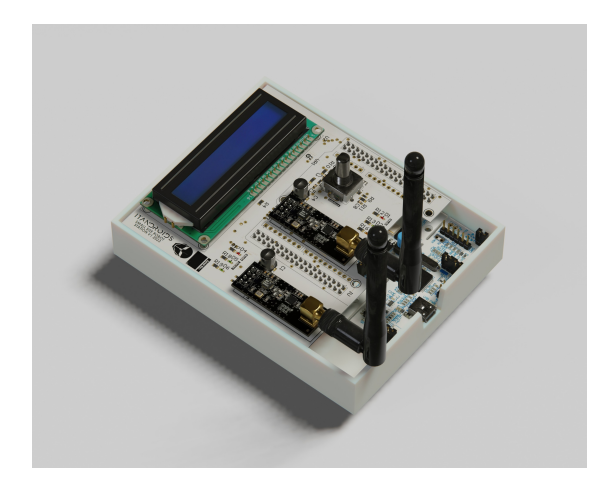
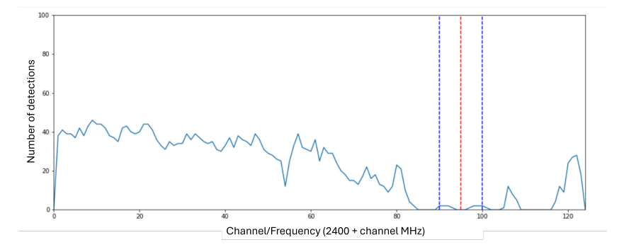
As mentioned in the previous team description paper (TDP) [6], we had severe communication problems at Latin American Robotics Competition (LARC) 2023, when we were already using the first iteration of Mainboard v2. The team raised several hypotheses: poor contact, spectrum interference, synchronization between robot and station, RTOS task configuration, radio configuration, antenna sensitivity and range, among others. These hypotheses served as the basis for the requirements of a new station, as shown in Fig. 1, whose first physical model was obtained in the first half of 2024. It was used in Robocup 2024 and Brazilian Robotics Competition (CBR) 2024 and, to the great satisfaction of the team, has not yet present any problems.
Over the past year, we tried to understand the origin of the communication problems experienced at LARC 2023. We made some tests, but, to be honest, we still do not fully understand what happened at LARC 2023. The good news is that, by all indications, the 2nd generation of the station has resolved the lack of robustness and reliability of the previous version.
2.2 IR sensor and kick delay
In the second half of 2024, we implemented a simple circuit on the robot's Mainboard responsible for ball detection using an infrared sensor. There is an emitter and a receiver on the front of the robot. The computer may send the kick signal continuously, while the electronics keep ready, but the robot kicks if only the receiver does not detect the infrared signal from the emitter (which means the ball is in front of the robot). The signal then passes through a MOSFET related to allow a high or low signal to be sent to the microcontroller. The IR sensor is a simple technique utilized in several SSL teams to avoid relying only on distance measurements through the camera and to bring more assertive and immediate behavior.
Additionally, we were able to reduce a half-second delay between the computer telling the robot to kick and the kick actually happening. This delay was included in the firmware to ensure that the robot's electronics were ready before the kick was activated, but proved too conservative. The IR and the reduction of this delay allowed for an almost zero response time between the kick command and execution, significantly enhancing the robot's performance during matches, and helped prevent double-touching the ball – we took a lot of fouls for that in the last Robocup.
3 Mechanics
The past year has seen notable advancements in the mechanical development of the ITAndroids team's robot. Key improvements include the development of a new damping system, as well as significant modifications aimed at improving cable management, optimizing capacitor placement, and reducing machining costs, all through the increased use of 3D-printed components.
3.1 Damping System
With the addition of a third robot to the team, new possibilities arose, such as diversifying ball passes. However, new challenges also emerged, as the dribbler system was not designed to efficiently receive passes.
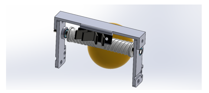
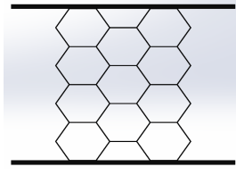
A novel damping system has been developed, initially drawing inspiration from the solutions developed by the TIGERs Mannheim [14] and Ri-one [7] teams. This system aims to improve impact absorption and stability, leading to smoother motion and better ball control. The integration process involved creating a support structure for the dampers, shown in Fig. 3, while ensuring compatibility with our existing design.
Both tested models performed better than the original configuration without damping; however, the ball still recoiled upon impact, making it difficult to control for an accurate shot. Therefore, an alternative system using foam instead of TPU dampers was tested. Although improvements were observed, the ball still exhibited some recoil. Currently, a new system is being studied, wrapping EVA foam around the dribbler roller. Tests have shown promising results, with the ball no longer recoiling after impact. However, in its current form, the damping system interferes with the kicker mechanism, rendering it impractical without further modifications.
3.2 3D-Printing Changes
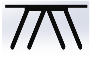
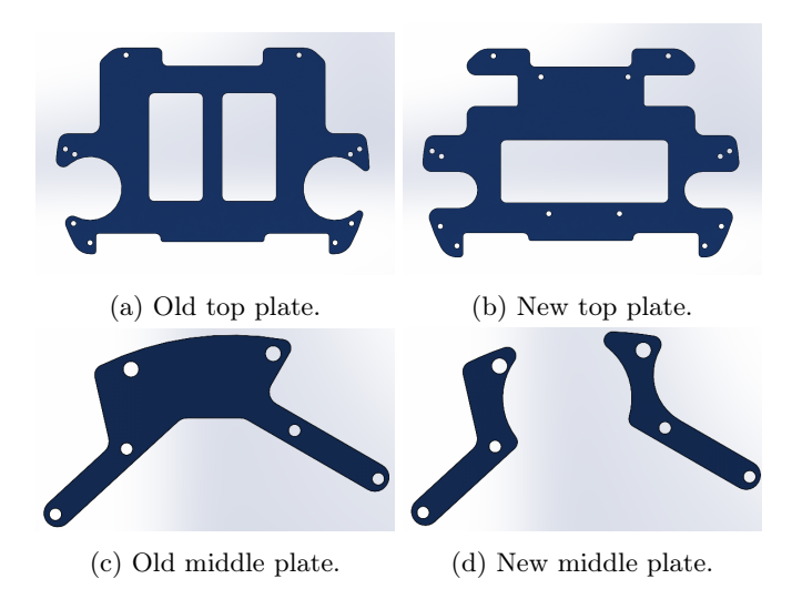
To allow for greater design flexibility and faster prototyping, especially for the dribbler system, several metal components have been replaced with 3D-printed alternatives. This transition also reduces manufacturing expenses, since parts such as the top and middle plates, shown in Fig. 4, can feasibly be made of plastic for permanent use. The materials used include PETG for the cover, TPU for the dampers, and PLA for other parts, chosen for their balance between strength and ease of printing.
This transition has also enabled an improved cable routing system, reducing interference and streamlining internal organization. In addition, the capacitors have been repositioned in a more optimal location, both to free up space for other circuits and to enhance the structural resilience of the robot to impacts.
4 Software
In this section we dive into our efforts related to our software in a general manner.
4.1 Aim at the goal
Our team previously employed a straightforward approach to goal-scoring, always aiming shots at the center of the goal. Nevertheless, this strategy did not account for the presence of defenders or the potential to optimize the shooting angle. To overcome these limitations, we implemented a more effective goalscoring method that involves performing a sweep of the area between the ball and the opponent's goal to identify obstacles and determine the best possible shot trajectory.
This process scans the field for defenders or other robots from our team that could obstruct a direct shot, allowing the system to map out the available shooting angles. If obstacles are detected, blocked regions are filtered out, isolating only the valid angles for a direct goal attempt. Among these options, the shot is directed along the bisector of the largest not obstructed angle, maximizing the probability of scoring while minimizing the impact of minor trajectory deviations caused by execution errors or external disturbances.
By dynamically adapting to the game scenario, this approach enhances the robots' ability to make precise and strategic shot decisions under varying conditions, making the attack more efficient and less predictable for opponents.
4.2 Path Planner
This year, we improved our visibility graph approach [9] by introducing blocked areas: polygonal regions that paths cannot cross. We currently use this feature to prevent robots from entering restricted zones (e.g., goal areas) and to avoid collisions with static field elements (e.g., goalposts).
We implement blocked areas by removing any edges in the visibility graph that intersect these polygons. Although this increases computational cost, it remains manageable for our real-time needs thanks to the efficiency of our algorithm. In addition to enforcing league rules, blocked areas also improve robot safety during gameplay.
We also addressed an issue where the destination could lie inside an obstacle, compromising the path planning process. Now, we dynamically reduce the obstacle's safety radius until the destination is free, unless that reduction matches the robot's radius (implying near-certain collision). This avoids failures when planning without compromising safety.
5 Control
In this section we present our recent works on control developing, both for low level and high level controllers.
5.1 Motor control
Plant transfer function Our team use BLDC motors for the wheels, and it's modeling is more complex than a DC motor modeling. However, there is a DC equivalent model for BLDC motors [8, 3]. There are two equations that relate the electrical model to the mechanical one [15], which are:
$$\begin{cases} J_m \dot{\omega}_m + B_m \omega_m = K_t i = \tau_m, \ V = L\dot{i} + Ri + K_t \omega_m, \end{cases}$$ (1)
where ω$^m$ is the motor rotation speed, V is the voltage applied to the motor terminals, i is the current circulating through the motor, J$^m$ is the motor inertia, B$^m$ is the coefficient of viscous friction of the motor axis, L and R are the terminal inductance and resistance, respectively, phase to phase of the motor, τ$^m$ is the torque generated by the motor, and K$^t$ is the torque constant of the motor.
In order to obtain B$^m$, we use:
$$B_m = K_t \frac{i_{nl}}{\omega_{nl}},$$ (2)
where i${nl}$ and ω${nl}$ represent no load current and no load rotation speed, respectively, both motor parameters.
Since there can be a gear reduction at the motor output to increase torque, there is a new set of equations:
$$\omega_l = \frac{\omega_m}{N}, \ \tau_{t,o} = N\eta\tau_{t,i},$$ (3)
where ω$^l$ is the load rotation speed, τ${t,o}$ and τ${t,i}$ are the transmission torques at the input and output of the gearbox, respectively, N is the gear reduction factor and η is the gear transmission efficiency.
Because of the gearbox, the torque motor now is used to rotate both the motor and the load. Thus adding τ${t,o}$ and τ${t,i}$ to the first equation of (1):
$$\begin{cases} \tau_m = J_m \dot{\omega}m + B_m \omega_m + \tau{t,i}, \ \tau_{t,o} = J_l \dot{\omega}_l + B_l \omega_l, \end{cases}$$ (4)
To estimate B$^l$, we use the linearization given by:
$$B_l = 2.5 \cdot 10^{-7} \left(\frac{\omega_{nl}}{N}\right)^{-1/3}$$ (5)
Using (3) in (4):
$$\underbrace{\left(J_m + \frac{J_l}{N^2 \eta}\right)}{J{eq}} \dot{\omega}m + \underbrace{\left(B_m + \frac{B_l}{N^2 \eta}\right)}{B_{eq}} \omega_m = \tau_m,$$ (6)
where J${eq}$ and B${eq}$ are equivalent inertia and coefficient of viscous friction, respectively.
Finally, considering a disturbance torque, τ$_e$, applied to the load, together with (3), we obtain:
$$\begin{cases} J_{eq}\dot{\omega}m + B{eq}\omega_m = \tau_m + \frac{\tau_e}{N\eta}, \ V - K_t\omega_m = L\dot{i} + Ri. \end{cases}$$ (7)
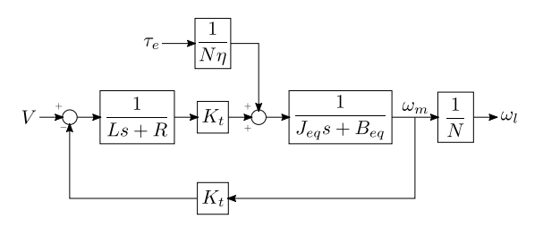
A block diagram which summarizes (7) is shown in Fig. 5. The total transfer function of a BLDC motor, from the input voltage to the motor velocity, is then:
$$G_m(s) = \frac{\omega_m(s)}{V} = \frac{K_t}{LJ_{eq}s^2 + (RJ_{eq} + LB_{eq})s + K_t^2 + RB_{eq}}$$ (8)
Parameter values for the BLDC motor employed as our wheel motors, EC-45 50 W 18 V, provided by Maxon.
| Value | Unit |
|---|---|
| 18 | V |
| 6720 | rpm |
| 247 | mA |
| 464 | m$\Omega$ |
| 322 | μH |
| 25.1 | mNm/A |
| 380 | rpm/V |
| 135 | g cm² |
| 48 | ppr |
Robot parameter values, obtained through CAD models and literature.
| Parameter | Value | Unit |
|---|---|---|
| Weight of robot | 2.23 | kg |
| Wheel radius | 36.25 | mm |
| Distance from center of robot to wheel | mm | |
| Wheel inertia | 243.62 | g cm² |
| Gear reduction factor | 3.47 | |
| Gear transmission efficiency | 94 | % |
PI controller design At first moment, as the controller design from the previous robot version was a PI controller, it was decided to continue with this controller topology. Thus, two requirements were defined, as [13] and [5] suggest: phase margin, PM${req}$, of 60° and bandwidth, W${req}$, of 30 Hz. With these requirements, the controller gains were analytically calculated and then used as an initial guess for an optimization by the Nelder-Mead algorithm (using fminsearch, a MATLAB function).
In order to determine the analytical gains, the closed-loop transfer function for the system (controller + plant) is required. The PI controller transfer function is given by:
$$C(s) = \frac{K_p s + K_i}{s},$$ (9)
where K$_p$ and K$_i$ represent, respectively, the P and I gains of the PI controller. With (8) and (9), the system closed-loop transfer function can be obtained. Moreover, considering that the current dynamics is much faster than the mechanical one, i.e., that L ≈ 0 , and ignoring the zero, a standard second-order system transfer function equivalent is obtained:
$$G_{mf}(s) = \frac{(K_p s + K_i)K_t}{RJ_{eq} s^2 + (K_t^2 + RB_{eq} + K_p K_t)s + K_t K_i} \equiv \frac{\omega_n^2}{s^2 + 2\xi\omega_n s + \omega_n^2},$$ (10)
where ξ and ω$_n$ can be calculated through the requirements defined previously and the set of equations given by:
$$\xi = \left{ \frac{1}{4} \left[ \frac{(2 + tg^2(PM_{req}))^2}{tg^4(PM_{req})} - 1 \right]^{-1} \right}^{1/4},$$ (11)
$$\omega_n = \frac{W_{req}}{\sqrt{1 - 2\xi^2 + \sqrt{4\xi^4 - 4\xi^2 + 2}}}.$$ (12)
Using (10), in conjunction with (11) and (12), the PI controller gains can be obtained:
$$K_{p} = \frac{2\xi\omega_{n}J_{eq}R - B_{eq}R - K_{t}^{2}}{K_{t}},$$ (13)
$$K_i = \frac{\omega_n^2 R J_{eq}}{K_t}.$$ (14)
Once the analytical values for the gains had been obtained, optimization was carried out using the Nelder-Mead algorithm, using the following as a cost function:
$$J(K_p, K_i) = (W_{req} - W(K_p, K_i))^2 + (PM_{req} - PM(K_p, K_i))^2,$$ (15)
where W(K$_p$, K$_i$) e PM(K$_p$, K$_i$) represent W and PM, bandwidth and phase margin, respectively, obtained for each gains set (K$_p$, K$_i$).
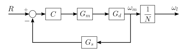
To proceed with the optimization, the dynamics from the motor current and from delay, caused by sampling, both for discretization, since it is a microcontroller operating in discrete time, and for Hall sensor sampling, were considered. The sampling dynamics from discretization and from Hall sensor sampling are represented, respectively, by G$_d$(s) and G$_s$(s), and they were obtained using a second-order Padé approximation. The final block diagram, considered for the optimization, is illustrated by Fig. 6.
5.2 Position Control
Our previous position controller strategy was basically a P controller with some heuristics to saturate the commands sent to the robot, to avoid slipping. Unfortunately, the P gain was guessed based on experimentation. With the team starting to develop more robust hardware, the interest to make the robots move with a higher performance increased.
As some teams already experimented with MIMO (Multiple-Input Multiple-Output) techniques without much success [16], the work focused on a classical SISO (Single-Input Single-Output) control approach. This way, the robot's movement is split into three different problems: translation along the planned path, translation normal to the path, and rotation.
For each controller, we will perform kinematic calculations to transform an arbitrary velocity v, such as a velocity along a line, into $\mathbf{v}_r = [v_t \ v_n \ \omega]^T$, the velocity in the local robot coordinate system, command this velocity to the plant, and obtain another velocity at its output.
Transfer Function Determination Let v be a scalar velocity in the global coordinate system. This velocity can be written as a linear combination of the local robot velocities $v_t$, $v_n$, and $\omega$. Let $\mathbf{E}$ be the transformation matrix converting from $\mathbf{v}r = [v_t \ v_n \ \omega]^T$, the velocity represented in the robot's local coordinate system, into this certain velocity v. The matrix $\mathbf{M}$ represents the inverse kinematics matrix, transforming $r\mathbf{v}{\omega} = r[\omega_1 \ \omega_2 \ \omega_3 \ \omega_4]^T$, which represents the angular speed of each robot wheel multiplied by the wheel radius, into $\mathbf{v}_r$. The matrix $\mathbf{M}^+$ is the pseudoinverse of $\mathbf{M}$, and r represents the wheel radius. So, we get:
$$v = \mathbf{E}\mathbf{v}r = \mathbf{E}r\mathbf{M}^+\mathbf{v}\omega.$$ (16)
However, ignoring coupling between motors and assuming all motors have the same transfer function, we find that $\mathbf{v}{\omega} = G(s)\mathbf{v}{\omega}^{r}$, where the superscript r denotes the reference value and G(s) denotes the closed-loop transfer function for the motor speed control, discussed in the last subsection. Thus:
$$v = \mathbf{E}r\mathbf{M}^{+}G(s)\mathbf{v}_{\omega}^{r}.$$ (17)
Since $r\mathbf{v}{\omega}^{r} = \mathbf{M}\mathbf{v}{r}^{r}$, we obtain:
$$v = \mathbf{E}r\mathbf{M}^{+}G(s)\frac{1}{r}\mathbf{M}\mathbf{v}{r}^{r} = \mathbf{E}\mathbf{M}^{+}\mathbf{M}\mathbf{v}{r}^{r}.$$ (18)
In general, $\mathbf{M}^+\mathbf{M} \neq \mathbf{I}$. However, if $\mathbf{M}^+$ is full rank, which is the case, since its columns respectively contain sin, cos, and constant terms and its dimension is 3x4, and $\mathbf{M}$ has linear independent columns, which is also the case, this pseudoinverse $\mathbf{M}^+$ is a left inverse, that is, $\mathbf{M}^+\mathbf{M} = \mathbf{I}$.
Thus, we conclude:
$$v = \mathbf{E}G(s)\mathbf{v}_r^r = G(s)v^r,$$ (19)
where v$^r$ is the reference for the velocity v.
So, the transfer function for a given scalar velocity v, ignoring coupling effects, is actually the closed-loop transfer function for the motor speed control.
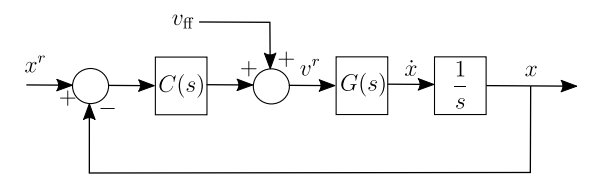
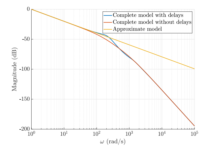
Project requirements Since the system transfer function, ignoring coupling effects, is actually the closed-loop for the motor speed control with an integrator, as shown in Fig. 7, this gives us some insights into the requirements for the project. As we expect a high performance control loop, it is only natural that we choose the higher bandwidth we can. From the system knowledge, since we know the system we are dealing with is actually an inner closed-loop control, we cannot let our loop have a bandwidth significant when compared to the inner loop.
Step response and stability margins for each designed controller.
| Controller type | Overshoot (%) | Rise time (ms) | Settling time (s) | GM (dB) | PM (deg) |
|---|---|---|---|---|---|
| P | 0.476 | 56.2 | 0.155 | 11 | 65.9 |
| PI | 3.38 | 54.2 | > 0.7 | 11 | 64.3 |
| Lag | 9.87 | 51.8 | 0.212 | 11.6 | 56 |
6 Conclusion and Future Work
ITAndroids has made significant progress in enhancing the performance and reliability of its SSL robots, with improvements in communication, ball control, software strategies, and motor control. The introduction of a new transceiver station addressed previous communication issues, while a redesigned damping system improved ball handling. Additionally, software enhancements, including optimized path planning and goal-scoring strategies, contributed to more effective in-game decision-making. Refinements in motor and position control also led to greater precision and stability, helping solidify our strong performance in last year's competitions.
Moving forward, we aim to refine AI-driven decision-making, optimize mechanical components, and further integrate hardware and software for a more adaptive and efficient system. A key focus will be implementing a curved kicking mechanism, applying our studies on neural networks to enhance shot accuracy and strategic versatility [2].
Acknowledgment
We would like to acknowledge the RoboCup community for sharing their developments and ideas. We especially acknowledge RoboFEI, Skuba and TIGERs for open sourcing their electronic and mechanic designs. Moreover, we would also like to thank members of CMDragons, RoboFEI and RoboIME for helping in various contexts. Finally, we thank our sponsors Altium, CENIC, Field Pro, Intel, ITAEx, MathWorks, Micropress, Neofield, Polimold, Rapid, Siatt, Solidworks, ST Microelectronics, Virtual Pyxis and Visiona.
References
- Freertos™. https://www.freertos.org/index.html (2023)
- Azevedo, F.A.B., Leão, G.P.C., Maximo, M.R.O.A.: Neural network design for a curved kicking mechanism with obstacle avoidance in robocup small size league (ssl). Journal of Intelligent & Robotic Systems 110, 124 (2024). https://doi.org/10.1007/s10846-024-02140-0
- Chern, T.L., Liu, L.H., Tien, C.W., Chen, C.Y.: Dsp-based brushless dc motor sensorless drivers with sine pwm. pp. 1349 – 1353 (12 2009). https://doi.org/10.1109/PEDS.2009.5385681
- Freiberger, A., Maximo, M.R.O.A., Loubach, D.: Implementation of firmware based on real-time operating system for small size league robot. Autonomous Computational Systems Lab, Aeronautics Institute of Technology, São José dos Campos, SP, Brazil
- Gene F. Franklin, J.D.P., Emami-Naeini, A.: Feedback control of dynamic systems. Prentice Hall, 7 edn. (2014)
- Gonçalves, A., Freiberger, A., Sousa, A., Souza, A., Silva, A., Yamamoto, B., Morais, E., Filho, F., da Hora, G., Barbosa, J., Santos, J., Neves, L., Barros, L., Fusinato, L., Alves, L., Mendonça, L., Máximo, M., Castro, M., Viana, M., Pedroso, M., Farias, N., Façanha, P., Barros, V., Sousa, Y.: ITAndroids Small Size Soccer Team Description Paper for RoboCup 2024
- Hirohashi, T., Matsumoto, Y., Tomioka, D., Naito, Y., Mitsuishi, K., Obara, T., Mitsushima, A., Murai, R., Okunishi, S., Ochiishi, K., Otake, S., Katsumi, B.: RoboCup 2024 Team Description Paper Ri-one (2024)
- Krykowski, K., Hetmańczyk, J.: Constant current models of brushless dc motor. Electrical, Control and Communication Engineering 3 (09 2013). https://doi.org/10.2478/ecce-2013-0010
- Maranhão, A., Schuch, A., Azevedo, A., Rodrigues, A., Lima, E., ao Sarmento, J., Santos, M., Maximo, M., Sales, M., Dias, M., Lima, R.: ITAndroids Small Size Soccer Team Description Paper for RoboCup 2020
- Maranhão, A., Schuch, A., Freiberger, A., Albani, A., Rodrigues, A., Simplício, E., Benicio, G., Haddad, L., Zoppi, L., Rezende, L., Maximo, M., Egger, M., Moreira, M., Silva, M., Celente, R., Lima, R., Augusto, V., Wakugawa, V.: ITAndroids Small Size Soccer Team Description Paper for RoboCup 2022
- Maxon: Maxon EC-45 Flat Brushless Motor 50W Datasheet. https://www.maxongroup.com/medias/sys_master/root/8833813119006/19-EN-263.pdf
- NordicSemiconductor: nrf24l01+. http://www.sparkfun.com/datasheets/Components/SMD/nRF24L01Pluss_Preliminary_Product_Specification_v1_0.pdf
- Ogata, K.: Modern control engineering. Prentice Hall, 5 edn. (2010)
- Ommer, N., Ryll, A., Geiger, M.: TIGERs Mannheim Extended Team Description for RoboCup 2022 (2022)
- Reis Pinheiro, F.C., Ricardo Omena de Albuquerque Máximo, M., Yoneyama, T.: Model predictive control for omnidirectional small size robot with motor and non-slipping constraints. In: 2019 Latin American Robotics Symposium (LARS), 2019 Brazilian Symposium on Robotics (SBR) and 2019 Workshop on Robotics in Education (WRE). pp. 13–18 (2019). https://doi.org/10.1109/LARS-SBR-WRE48964.2019.00011
- Sherback, M., Purwin, O., D'Andrea, R.: Real-time motion planning and control in the 2005 cornell robocup system. In: Kozłowski, K. (ed.) Robot Motion and Control. pp. 245–263. Springer London, London (2006)
- ST: Stm32 nucleo-32 boards mb1180 manual. https://www.st.com/resource/en/user_manual/um1956-stm32-nucleo32-boards-mb1180-stmicroelectronics.pdf
- STMicroelectronics: STM32H753xI (April 2019), rev 7
- STMicroelectronics: STM32 Nucleo-64 Boards User Manual (August 2020), rev 14