Project Neon Description Paper for RoboCup 2025
Alexandre Keiti Fukamati, Ana Julia Monici Orbetelli, Diego Boasso, Eduardo Yukio Makita, João Pedro Kayano Leal, Letícia Martins, Marcos Augusto Pacheco, Marcus Holanda, Nayara Victoria Verissimo Matos, Valentina Sierra Ceballos
Universidade Federal do ABC Paulista, Santo André, São Paulo, Brasil
Abstract This article gives an overview of what has been done for Project Neon´s SSL participation in 2025, describing the main changes from last year's project. We have described what has been done in the technical areas as well as our new organizational approach to the development of our robots and game strategies.
Overview
This section introduces the team and its innovations.
Team
The Team was founded in 2015 by students from the Federal University of ABC and is currently composed of various members from different fields of knowledge. One of the most important pillars adopted by the team is the concept of open-source: all work developed is open, whether hardware or software, for anyone to use, allowing a network of open collaboration and learning. Our first participation in SSL was in 2023. Although we did not manage to play a match, we had important lessons for our second participation. Thus, the goal this year was to create a more robust management for the project development, which required the creation of some processes, documents, and the addition of more members to the team. We went from 5 people to 13. In this document, we will explain what changes and innovations were made compared to last year and how it was to develop these solutions as a team.
Innovation
Motor: Use of camera stabilizer motors, a cheaper alternative to the motors normally used in the category.
Electronics: Modular approach with 3 microcontrollers to facilitate firmware development and ensure a high update rate of the control loop. Through two dev kits, two Blue Pills, and one ESP32.
Team Organization
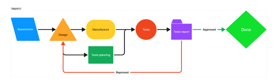
One of the biggest difficulties compared to the VSSS category is the greater number of challenges to be developed and the need for efficient integration to respect the maximum dimension. This creates a difficulty regarding development time, due to the great interdependence of each part and consequent linearity of implementing one challenge after another, resulting in longer development time. To optimize time, the approach is to create a bench prototype for each of the developed challenges. At this stage, the solution's dimension or integration to the robot does not matter, only its functionality. In this way, it is possible to develop in parallel. For this, we divided the team members, preferably in pairs, to focus on each of the challenges, being divided into: locomotion, control, kicker, dribbler, firmware, and electronics. Additionally, we used the project development process in Figure 1, which improved accuracy and consequently reduced the number of adjustments in each of the developed challenges.
Mechanical and Electrical System
This section describes the mechanical design and electrical components of the robot.
Robot Configuration
The main aim of our project was to cheapen and simplify locomotion, in which there are usually two main problems: expensive motors (around 100 USD) and an expensive gearbox assembly. Therefore, our project focused on finding an alternative to avoid using a reduction set, which means it is necessary to choose a motor with high torque and dimensions corresponding to the robot's size. With these two characteristics, the ideal type of motor is the BLDC, widely used in drones. However, these motors do not present important technical data for locomotion sizing calculation, so we specifically have to look for motors with low Kv (RPM constant per Volt applied) and larger diameter, both indications of a BLDC motor with higher torque.
The main results of our research were: FlyCat 5010-360Kv motor (11.90 USD) and Ipower 4108-50Kv motor (36 USD). When comparing their characteristics, we chose the Ipower due to its high coil impedance (11 Ohms). Although this is a factor that limits the motor's performance and efficiency, we have a higher torque per ampere ratio, making the requirements more simplified for the motor driver, as only 20V and 2A will be needed. The wheel arrangement has changed compared to last year to ensure more space between the motors to incorporate the new kicker and the dribbler that is under development. The angle change was from 30 degrees for the top wheels and 45 degrees for the bottom wheels on the 2023 robot, to 30 degrees on all wheels on this year's robot (the angles are in relation to the horizontal line that crosses the robot's center). Table 1 shows the robot's main characteristics and what changes it has made compared to last year.
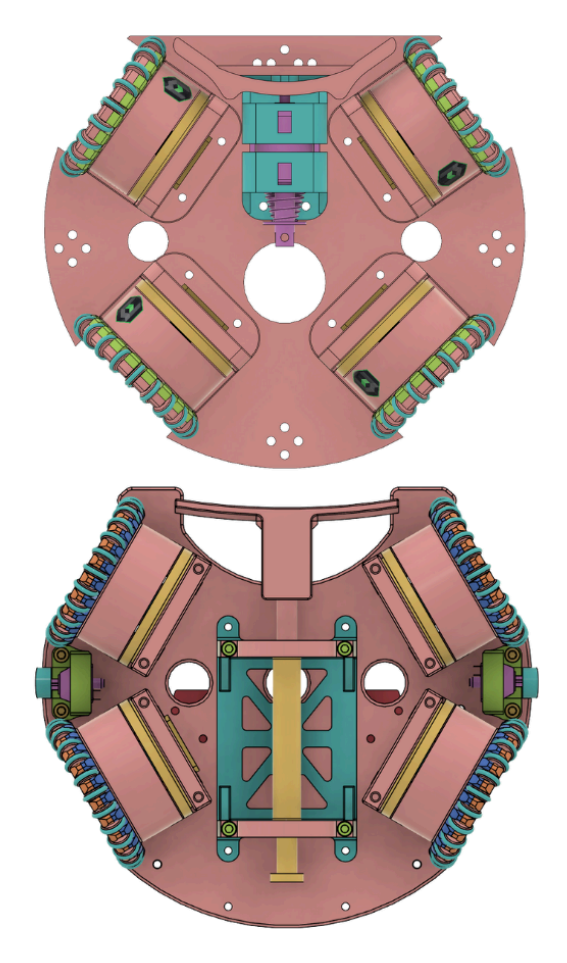
Robot main characteristics and changes compared to last year
| Characteristics | 2023 | 2024 |
|---|---|---|
| Dimension | Ø180 x 148mm | Ø180 x 148mm |
| Total Weight | 1.6kg | 2.2kg |
| Total Weight | Ipower 4108 | Ipower 4108 |
| Max ball coverage | 12% | 19% |
| Driving Motors | Ipower 4108 | Ipower 4108 |
| Gear | 1:1 | 1:1 |
| Wheel diameter | 61mm | 61mm |
| Dribbling motor | - | Generic BLDC 2212 1000Kv |
| Dribbling bar diameter | - | 12mm |
Kicker
In order to improve the robot's integration and performance, we developed our own solenoid, allowing for more precise sizing of the factors that influence its efficiency and strength, as well as optimizing the use of space.
Currently, the kicker consists of a single solenoid dedicated to the straight kick. Its coil, printed on PLA, is 66 mm long, 31 mm in diameter and has approximately 700 turns of AWG 22 enameled copper wire. The piston is made from 1020 steel and aluminum. With this configuration, the speed of the ball reaches around 1.5 m/s.
Electronics
This section describes the electronic systems of the robot.
Motor Driver
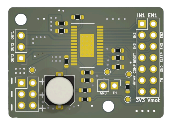
Given the requirements of 20V and 2A, it is easy to find an IC (Integrated Circuit) for controlling BLDC motors with integrated MOSFETs. The DRV 8313 was chosen because it has no integrated control and this gives us greater flexibility to control the motors, as well as greater performance, given the direct coupling of the motors to the wheels and the dynamic nature of the application.
Thus, the motor driver consists only of the IC with 3 half H bridges, the method of switching and controlling the motor has to be done by an external microcontroller, in this case we chose the STM32F103 to control two motors using the "Simple FOC" library [7]. We chose the voltage torque control method, which uses sinusoidal commutation. Thus, it is not necessary to measure the current due to the effect of the motor's high impedance, since we do not have the lag effect between voltage and current that the FOC method aims to reduce.
Kicker
The kicker is activated by a mosfet, which works like a switch. This mosfet is controlled by an output signal from a microcontroller, which determines when the solenoid will be activated.
To supply the solenoid with the necessary energy, a 4700 µF electrolytic capacitor is used as temporary energy storage. This capacitor is charged by means of a flyback transformer, which receives electrical pulses generated by a second Mosfet. This second Mosfet is controlled by another signal from the microcontroller, which controls the switching of the transformer, allowing the input voltage to be converted and the capacitor to be charged.
The capacitor is directly coupled to the solenoid, so that when the first mosfet is triggered, the energy stored in the capacitor is drained through the solenoid.
In the previous year, the energy stored in the capacitor was supplied by a step-up module that raises the input voltage level to a level suitable for the Kicker's operation. However, the use of this module was limited by its maximum supply capacity of 35V, which is why a flyback transformer was used. This substitution reduces thermal energy losses and increases the output voltage.
Main Board
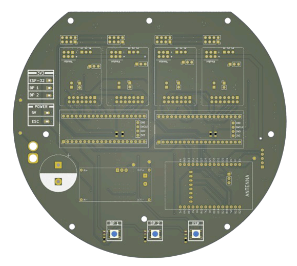
This board is responsible for connecting all the modules and has also been designed in such a way that it is easy to make any component changes without having to solder. In addition, there are LEDs to identify operating modes and error logs.
Firmware
This section describes the firmware architecture and control systems.
Architecture
Communication will be performed using the ESP-NOW protocol - a wireless communication protocol based on the IEEE 802.11 standard supported by the ESP8266, ESP32, ESP32-S and ESP32-C chips. This protocol is characterized by simplified transmission, eliminating the OSI layers and with a very straightforward implementation. Furthermore, following the project proposal, the acquisition of ESP32 chips has a relatively affordable cost compared to other possible solutions.
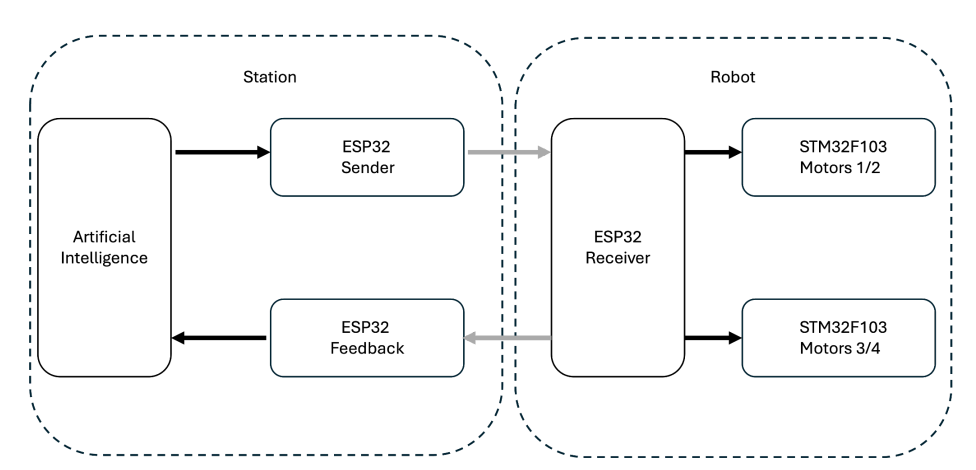
The communication process is performed using three ESP32s: one to send decision-making information to the robot; one to receive information from the robot and return it as feedback; and a board for the robot, responsible for both sending information from the robot to the control boards and sending information from the robot to the feedback. This structure was proposed to simplify the implementation of the project, avoiding the occurrence of communication conflicts between the station and the robot, using a specialized board for feedback. Figure 6 shows a graphical representation of the communication flow.
According to the flowchart presented, it is possible to observe that the system can be fed back with information provided by the robot, enabling this information to be used in the future to improve decision-making. However, the feedback will initially be used to monitor the robot and provide data such as: battery level, RSSI (Received Signal Strength Indication) and error codes. This data does not directly influence robot control, but it allows debugging to be carried out easily, being essential in the first iterations of the project.
After sending information to the robot, the data will be sent to each of the components responsible for each task, such as the motors and the kick mechanism. Thus, communication works based on the 60 Hz update rate of the artificial intelligence to ensure that data is not lost. Therefore, all wireless communication occurs through ESP32 using the ESP-NOW protocol, with a mechanism for obtaining information for feedback and ensuring that information is delivered to the robot.
Data Structure
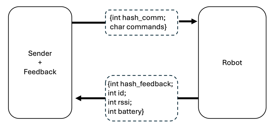
To perform this information exchange using ESP-NOW, an authentication hash is used between peers, both for the robot's communication with the station, and for the robot's communication with the feedback. This hash ensures that the information processed by each of the steps is the desired information. Thus, the information is stored in the form of structs, with different structs for the robot's commands and for the feedback. Furthermore, for a team of N robots, the robot's locomotion commands are broadcast in a string in the format shown below:
<id1,vx1,vy1,theta1,kick1,…,idN,vxN,vyN,thetaN,kickN>
In this way, based on the identification sent, the robots identify the information intended for them, and then, based on the values provided by this string, the robot locally calculates the speed to be provided by the motor, and also responds to the kick command if it is sent. Finally, we can sketch the information structures exchanged by the robot as shown in Figure 7.
However, the use of strings to send data also occurs in the feedback reception phase. In this case, the strings are formed after receiving information from each robot, obtaining the format shown below:
<id1,rssi1,battery1>...<idN,rssiN,batteryN>
This transformation is necessary because this information is returned to the decision algorithm, which will ultimately send it to the graphical interface, facilitating the display of this information. Thus, this information is transformed into this string that is communicated to a thread of our decision-making algorithm through a serial port.
Motor Control
Two STM32F103 microcontrollers were used to control the motors, each of which was responsible for driving a pair of motors. This separation was done to facilitate code development and maintenance. Thus, each of them was responsible for driving two motors with the help of SimpleFoc.
Upon receiving the locomotion information, the robot's ESP32 calculates the speed of each of the wheels and is responsible for sending this information to the STM32F103. Communication between the robot's ESP32 and the STM32F103 was also done via serial ports. To do this, the speed information for each motor was also converted into strings, which in this case were in the format:
<0,motor1,motor2,1,motor3,motor4>
Thus, each STM32F103 is responsible for receiving information regarding its respective motors, and finally performing the movement according to the speed value sent.
Artificial Intelligence
This section describes the AI and decision-making systems.
Architecture
As a new team in the SSL category, our primary goal in software development was to establish a solid foundation for future strategy development. By studying how other teams structure their software and drawing from our experience in the IEEE VSSS [1], we defined three key tenets.
Participation in the project is considered an extension activity, requiring approximately six hours of commitment per week. No prior knowledge is expected from new members, so we strive to align our technologies with the fundamental concepts taught in early university courses. Our development approach prioritizes both innovation and speed, and we have structured our software accordingly to support these goals.
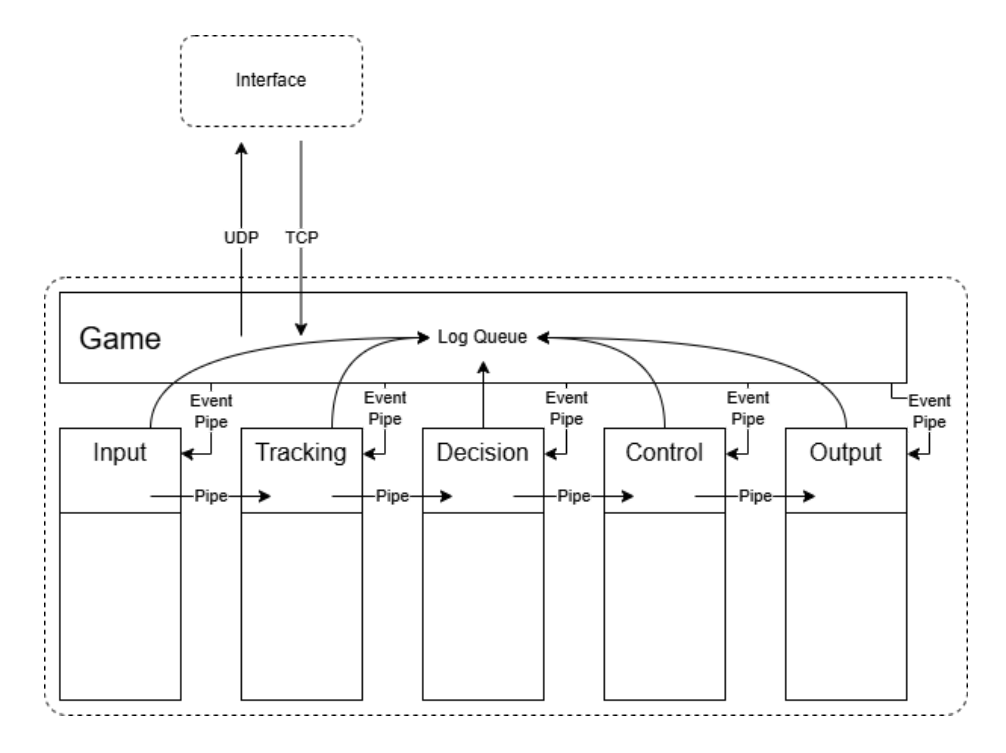
Based on these principles, we adopted a layered architecture, as illustrated in Figure 1. The entire software system is designed as a pipeline, where each layer represents a distinct processing step. Each step functions as an independent process running concurrently. This approach enables even those with minimal experience to clearly identify where existing or new functionalities should be integrated. Additionally, it facilitates debugging at the layer level and allows for precise performance measurements to identify bottlenecks.
Input Layer. In the first step, all input data is collected. This layer manages multiple threads responsible for communication with SSL Vision, the Game Controller, and robot sensor feedback. It does not perform any data cleaning or preprocessing, except for unit conversion to standardize inputs from different sources.
Tracking Layer. This layer applies filters and merges data from different sources into a unified world model. In addition to tracking field entities (robots and the ball), it calculates ball possession and determines the game state (e.g., playing, free kick, halt).
Decision Layer. This layer determines the actions for all robots, including their target positions and additional behaviors such as kicking or dribbling. It follows a specific architecture that will be detailed in the next section.
Control Layer. In this step, paths and global desired velocities are computed for all robots. Additional checks are performed to ensure that final speeds comply with speed limit regulations.
Output Layer. As the final step, this layer is responsible for transmitting the target speeds to the intended destination, which could be either the simulator or the actual robots via the ESP32 station.
Decision making
The decision layer uses a more structured architecture to simplify its development. It combines ER-Force's multi-agent system [2] and Hungarian positioning system.
Coach. Decision-making begins with the coach module, which assigns action agents and determines their roles. The remaining n robots are added to the Hungarian pool, the coach assigns n positional roles.
Hungarian agents. Hungarian agents are robots whose only action is movement. At each decision step, the coach selects a set of positional roles equal to the number of Hungarian agents, with each role providing a target position. The coach then applies the Hungarian method [3] to assign each robot to a target position in a way that minimizes total travel distance.
Action agents. Action agents are robots capable of more than just movement—they can shoot, pass, or dribble. These robots are excluded from the Hungarian algorithm assignment and instead execute predefined strategies based on their assigned roles.
Each strategy is implemented as a finite state machine (FSM), where each node represents a skill. Skills are also FSMs but represent specific actions, such as passing, moving, or shooting.
Dribbler
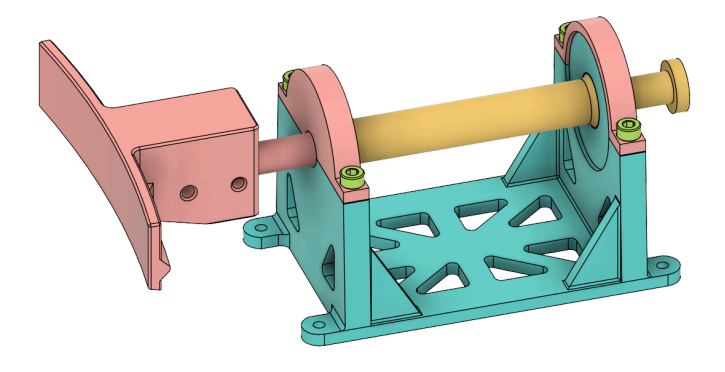
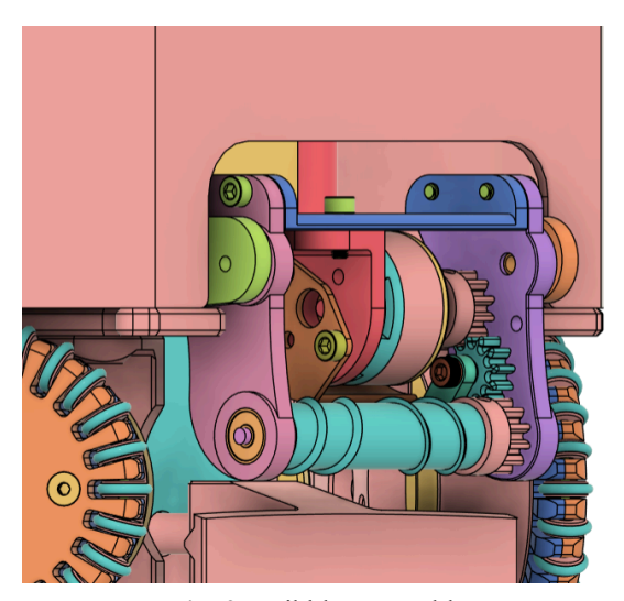
The dribbler is responsible for the dampening and control of the ball during the game. To make this happen, a structure was created with 3D printing – using PLA – that pivots around an axis to help with the damping effect. This mechanism was inspired by the luhbots Soccer dribbler made in 2022 [5] and adapted to the geometry of the robot that needs the pivot to be in the upper part of the structure. To ensure a good control of the ball, the roller was made using silicone shore A14 with a helical design – similar to the one made by TIGERs Mannheim [6] – to help centralize the ball and improve the kicker's precision and accuracy. The roller is made using a 3D printed mold with a stainless steel rod as its axis.
To activate the dribbler, a BLDC 2212 1000kv motor is fixed at the top of the structure that utilizes three gears of the same size to rotate the roller, which is fixed using two bearings on the side. Figure 8 shows the dribbler – using different colors for different components to help visualization – on the robot and below are the materials used to assemble it.
Materials
Roller made of silicone shore A14, 12 mm of diameter; 3 PLA 12 teeth gears size 14 mm diameter tip; BLDC 2212 1000kv motor; 2 623ZZ bearings.
References
- Batista, L., Brighenti, I., Dias, G., Fernandes, T., Flores, L., Giannattasio, R., Leal, J., Lima, M., Makita, E., Orbetelli, A., Pacheco, M., Sampaio, J., dos Santos, A., Torres, G. : Project Neon 2023 Very Small Size Soccer, Latin American Robotics Competition, São Paulo, Brazil, 2023
- Harald, B., Danzer, A., Eischer, M., Hauck, A., Hoffmann, M., Kallwies, P., Lieret, M.: ER-Force Team Description Paper for RoboCup 2014. (2014)
- Harold W. Kuhn, "The Hungarian Method for the assignment problem", Naval Research Logistics Quarterly, 2: 83–97, 1955.
- Silva, C., Martins, F., Machado, J.G., Cavalcanti, L., Sousa, R., Fernandes, R., Araújo, V., Silva, V., Barros, E., Bassani, H.F., de Mattos Neto, P.S.G., Ren, T.I.: Robôcin 2019 team description paper (2019), robocup Small Size League, Recife, Brazil, 2019
- Seegemann, L., Zeug, F., Ebbighausen, P., Waldhoff, L., Westermann, M., Knackstedt, S., Kännner, M., Fächsel, T, Hart, R., Pahl, T. luhbots Soccer Team Description for RoboCup 2023.
- Engelhardt, T., Heineken, T., Kühn, T., Lindner, J., Schmidt, M., Schofer, F., Seifert, C., Stadler, M., Wegmann, L., Wendler, A.: ER-Force 2019 Extended Team Description Paper. (2019)
- Antun Skuric, Hasan Sinan Bank, Richard Unger, Owen Williams, and David González-Reyes. 2022. SimpleFOC: A Field Oriented Control (FOC) Library for Controlling Brushless Direct Current (BLDC) and Stepper Motors. Journal of Open Source Software 7, 74 (2022), 4232. https://doi.org/10.21105/joss.04232
- Silva, S., Alves, C., Martins, F., Machado, J. G., Damurie, J., Cavalcanti, L., Vinícius, M., Souza, R., Rodrigues, R., Fernandes, R., Morais, R., Araújo, V., Silva, W., Barros, E., Bassani, H., Mattos Neto, P. S. G., Ren, T. I.: RobôCIN 2020 Team Description Paper, Pernambuco, Brazil, 2023.