RoboCup 2025 TEAM DESCRIPTION PAPER Ri-one
Daiki Tomioka, Yuzuru Naito, Kaito Mitsuishi, Shutaro Otake, Bunichi Katsumi, Koutaro Ochiishi, Riku Miyazaki, Takumi Banba, Mitsuyoshi Sugaya
College of Information Science and Engineering, Ritsumeikan University, Iwakura-cho, Ibaraki-shi, Osaka-fu, Japan
Abstract This paper is about our team's bid to qualify for the RoboCup -2025 soccer small size league tournament. In addition, our team's robot and system are redesigned according to the result of RoboCup2024. Our organization conducts research and analysis in the areas of hardware, circuits, and software. In hardware, we will propose our newly developed dribblers, taking into account the improvements of the previous air-frame. In circuitry, we worked on developing a motor driver and made changes to the control system. Finally, in software, we propose a new ball detection method and the selection of the optimal route searching algorithm. Our approach should appropriate in the competition.
Keywords: RoboCup · soccer small size league · autonomous robot · engineering education.
Introduction
We, Ri-one, are a student organization aiming to be the best RoboCup team in the world, recognized as a project team by the College of Information Science and Technology, Ritsumeikan University. Our team was formed 4 years ago and participated in the world competition for the first time at RoboCup 2022 Bangkok, where we placed 5th, in Bordeaux the year before last, where we placed 3rd, and in Eindhoven last year, where we won the world championship. We are currently proceeding with development in preparation for the challenge of Division A. This paper is a continuation of the Team Description Paper for Robocup 2024, and introduces improvements and new developments compared to the previous version.
Dribblers
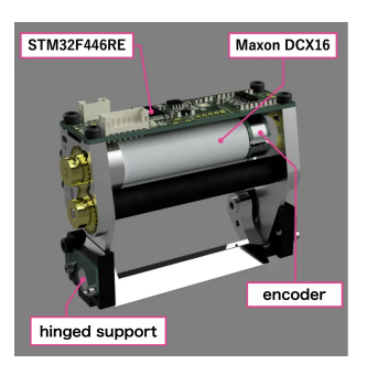
The dribblers employed until the previous year utilized a linear motion mechanism with linear guides. In contrast, the novel dribbler employs a rotary mechanism, as depicted in Fig 1. This redesign facilitates miniaturization and unitization, enhancing its functionality and efficiency.
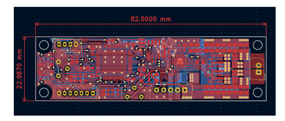
In order to achieve a smaller board size, a gate driver called DRV8701 was used, as illustrated in Fig 2. This motor driver can sense the current flowing in the motor and does not require an external operational amplifier. By reading the motor current, it is possible to accurately determine if the ball is dribbling, thus preventing double touches, for example. In addition, an incremental encoder was installed to measure the number of motor revolutions. The current value and motor speed are then leveraged to regulate the motor output in conjunction with the STM32F446RE. These functions are instrumental in synchronizing the number of rotations of the ball with the number of rotations of the dribbler tube upon receiving a pass, thereby ensuring stable pass reception.
Motor Driver
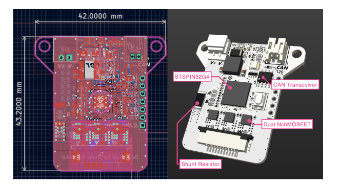
The larger kicker necessitated a reduction in the size of the circuit, thus prompting the development of a smaller motor driver. The decision was made to renew the previously utilized combination of the STM32F446RE and DRV8300, which had been employed in the development of the motor driver, and to adopt the STSPIN32G4, a gate driver and microcontroller in one package. This package, measuring 9 × 9 mm$^2$, contains a gate driver, STM32G431, a buck converter, a 3.3V low-dropout (LDO) regulator, and op-amps. Notably, the chip integrates all the essential functions for brushless motor control, enabling the reduction of board size and the number of components required for operation, such as the CAN and power supply connections. Fig 3 illustrates the configuration of the BLDC driver circuit.
Control System
The robot system underwent substantial modifications from its previous iteration. Previously, the robot's circuits were configured on a single main board. However, the design was modified to distribute the boards based on their function, with the addition of the Kicker-Board, Power-Distribution-Board, and Power-Board, as depicted in Fig 4. The microcontrollers on each board communicate with each other via CAN communication, and the system enables other boards to recognize when an abnormality is detected on another board. The CAN communication system facilitates the mounting of all devices on a single communication line, thereby streamlining the operational process. In the absence of a Main-Board, the attachment of a device capable of CAN communication to the communication line and the subsequent transmission of data enables the testing of the API of the Kicker-Board or the motor driver's API. This feature offers a significant advantage in operational styles that necessitate high production rates, such as SSL, where effective parts management through maintenance is paramount.
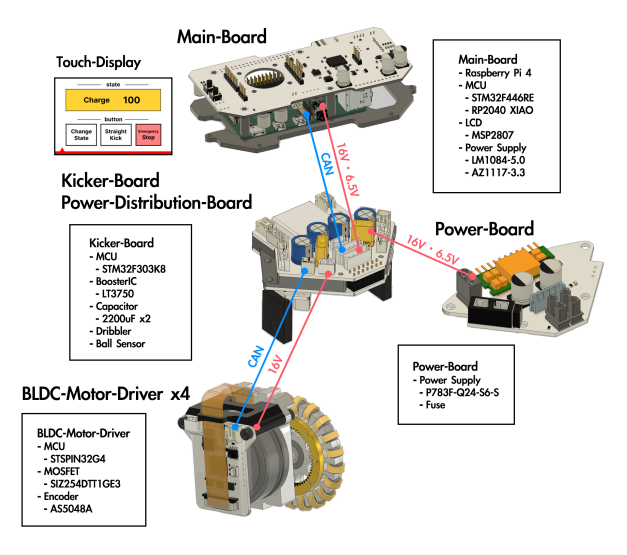
Power-Board The device is equipped with a resettable breaker and an ideal diode, a safety feature that protects against failure due to reverse battery connection and fault expansion in the event of overcurrent. Additionally, a DC-DC converter is incorporated to generate 6.5V from 16V. The 6.5V generated within the device is utilized by another board to regulate the voltage.
Power-Distribution-Board The device has the capacity to distribute the power supplied through the Power-Board. The distribution of power is facilitated through three lines: 16V, 6.5V, and the CAN communication line. The distribution of power to the Main-Board, BLDC-Motor-Driver, and Kicker-Board is facilitated by this board.
Kicker-Board The board under consideration produces 200 volts for the kicker, monitors the ball, drives the dribbler, and manages charging and discharging of the capacitors. It is equipped with STM32F303K8 and provides API via CAN communication. In the event that the Main-Board is tasked with determining the presence or absence of the ball, its reaction time is expected to be sluggish. Consequently, the Kicker-Board assumes responsibility for monitoring the ball and making decisions regarding its movement. The transmission of sensor values and associated data to the robot's network is facilitated by CAN communication, a method that enables real-time monitoring by the Main-Board or by connecting a development PC to the robot's network via a USB-CAN adapter.
Main-Board The Touch Display is composed of the RP2040, which manages the Touch Display, the F446RE, which manages the motion control of the robot, and the Raspberry Pi 4B, which handles communication and recognition with the camera. The Touch Display is capable of performing a variety of functions, including the initiation of charging the kicker, the testing of the kicker, and the discharge of the kicker. It also possesses numerous useful functions for making adjustments to the robot.
Robot Hardware Debugging Tool
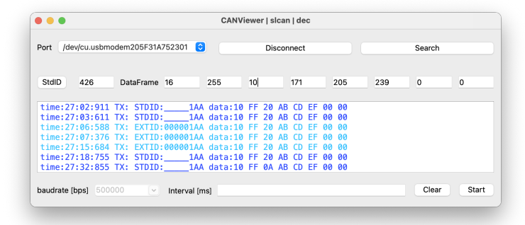
As explained in the previous chapter, the robot's hardware is connected to CAN-BUS; by monitoring the data flowing on the bus, we can now check that the robot's communication is working correctly. We use CANable 2.0 and CAN-Viewer as debugging tools: CANable 2.0 is an open source STM32 based hardware that allows us to view CAN data frames by connecting it to a PC via USB. CANViewer is a visualisation software that is compatible with CANable and is available on GitHub and can be used on Windows, Mac and Ubuntu. It was developed by members of Ri-one and has been developed and improved by our team. We use this tool when unit testing circuits and developing embedded software. The CANViewer screen is easy to use, as shown in Fig 5
Software Design
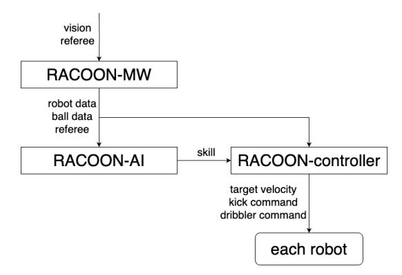
To optimize the high-level control system, we have updated the software design. Data received from the vision system and the GC is processed by RACOON-MW and then sent to other software modules. RACOON-AI analyzes the field and determines the positioning and skills for each robot. The skills available to RACOON-AI are provided by the RACOON-controller. In the RACOONcontroller, commands such as the robot's target speeds and kick commands are generated to enable skills like moving, ball catching, and shooting, and these commands are then sent to the robots.
Position Control
Within the local control system, the robot's velocity control is implemented. In the RACOON-controller, the velocity command is used as a reference for controlling the robot's position. The position control of the robot is achieved through path planning and path tracking. For these algorithms, we have adopted RRT* and DWA.
RRT* Rapidly-exploring Random Tree Star (RRT*) is a probabilistic sampling-based algorithm for robot path planning. Compared to the conventional RRT, it guarantees optimality, allowing for the optimal solution (such as the shortest path) to be obtained.
To ensure that processing is completed within one control cycle, we made the following adjustments. The process of reassigning parent nodes is performed for all nodes that exist within 3000 mm of a given node. Additionally, new nodes are configured to be placed at a point 100 mm away from an existing node. Furthermore, as part of the sampling strategy, the goal point is directly selected with a probability of 10Moreover, a minimum number of iterations is set so that even if a path is found within a certain number of iterations, new nodes continue to be added beyond that lower limit. This ensures that even after an initial path is secured, the exploration continues and the overall path is further optimized. In addition, if a robot is already located inside an obstacle (for example, in a defensive area), the closest point outside the obstacle is chosen as the target point. This allows the robot to quickly exit the obstacle and transition to a safe state.
DWA The Dynamic Window Approach (DWA) is a local path planning algorithm that takes the robot's dynamic constraints into account. In order to safely and efficiently reach the target point while avoiding obstacles in the environment, it selects the optimal acceleration candidate from among those available for the robot. This algorithm evaluates the robot's trajectory and changes in velocity, and from among the acceleration candidates that pose no risk of collision with obstacles, it adopts the one with the highest score. The candidate accelerations are generated based on the robot's maximum acceleration, $a_{max}$, according to the following formula:
$$\boldsymbol{a} = \frac{n}{10} a_{max} \begin{pmatrix} \cos \theta \ \sin \theta \end{pmatrix}, \ n = 1, 2, ..., 10$$
Here, $\theta$ starts at $-\pi$ and increases by a common difference of $\frac{\pi}{4}$ for each candidate. This method generates acceleration candidates at various angles relative to the robot's direction of travel, thereby enabling extensive exploration.
The behavior of the robot when each acceleration candidate is applied for 0.4 seconds is evaluated based on the following three elements:
- $-d_{path}$: The deviation of the robot from the ideal path (trajectory error)
- $-d_{goal}$: The distance to the target point
- $-d_{vel}$: The difference between the robot's actual velocity and the ideal velocity
Each of these evaluation metrics is assigned a weight— $w_{path}$, $w_{goal}$, and $w_{vel}$, respectively—and the final score is calculated as follows:
$$score = w_{path} \exp(-d_{path}) + w_{goal} \exp(-d_{goal}) + w_{vel} \exp(-d_{vel})$$
In order to ensure that obstacles are sufficiently avoided while reaching the target along the path as quickly as possible, each parameter was tuned, and smooth operation was confirmed with the following values:
DWA Parameters
| parameter | value |
|---|---|
| $w_{path}$ | 0.4 |
| $w_{goal}$ | 2 |
| $w_{vel}$ | 2.5 |
Robot Obstacle Determination In path planning, it is necessary to appropriately take into account the movement of obstacles. In our approach to trajectory generation for each robot, we predict the region in which other robots might be present and treat that entire region as an obstacle. This potential region is defined as the set of positions a robot can reach within a given time under acceleration constraints. The prediction time varies depending on the distance to the robot, with longer prediction times used for robots that are farther away.
Result By combining these methods, effective avoidance of static obstacles—such as defense areas and field walls—was achieved. However, the system did not yield satisfactory results in avoiding collisions between robots. This issue stems from the fact that DWA selects acceleration based solely on local evaluations, making it unable to consider the overall safety of the trajectory or the optimality of travel time. Specifically, since DWA evaluates only the current acceleration, it is challenging to ensure the overall safety of the trajectory, and the resultant speeds do not guarantee the optimal travel time along the entire path.
As a solution, it is considered effective to introduce a trajectory generation algorithm between RRT* and DWA. By explicitly associating the robot's position with time, the trajectory generation algorithm can enhance the precision of dynamic obstacle avoidance. Furthermore, this would allow DWA to focus exclusively on local obstacle avoidance, thereby reducing the burden of optimizing the arrival time at the target and simplifying parameter tuning.
Transmission of Image Data
Recent improvements in Wi-Fi bandwidth performance have made it possible to transfer larger amounts of data in a shorter period. To enable more detailed monitoring of the robot's status, we have developed a system that transmits the video from the cameras mounted on the robot in real time.
Compression Method If image data is not compressed, the resulting file sizes can be extremely large depending on the resolution. To further improve data transmission efficiency, it is necessary to compress the video data. The Raspberry Pi used in the robot is equipped with an H.264 encoder, providing hardware capable of efficiently encoding the data. By compressing the data with H.264, it is possible to minimize the amount of data required for streaming.
Transmission Capacity Measurements of the data capacity that the robot can transmit show approximately 200 Mbit/s. Since streaming the robot's camera video requires an average bandwidth of about 5 Mbit/s, this confirms that sufficient transmission capacity is available.
Ball Detection
We proposed a ball recognition method by YOLO, a deep learning model last year. It suffers a couple of issues, including its delay and the necessity of a proper dataset. Hence, YOLO was utilized solely for determining the initial parameters, while ball detection was implemented through a conventional color-based detection approach. Our new method includes the following functions to achieve high-speed and accurate detection.
Dynamic ROI The Region of Interest (ROI) refers to a specific area within an image targeted for focused processing or analysis. It improves accuracy and performance since we search in a small area. It is based on the previous ball's position. This method enabled us to reduce the processing time.
Evaluation of the circularity The detected color region should ideally exhibit a circular shape. Circularity was introduced to enhance the accuracy of detecting regions resembling a ball. It quantifies the complexity of a shape, with values approaching 1 for shapes that closely approximate a perfect circle. It is typically defined as follows:
$$Circularity = \frac{4\pi S}{L^2}$$
Here, $S$ represents the area of the region, and $L$ denotes the perimeter of the region. Regions with a circularity above a predefined threshold are considered potential ball regions.
Conclusion
In this paper, we have discussed and introduced our new improvements. As mentioned, our team has been focusing on developing both our software system and the hardware of our machines, and these improvements are expected to contribute to a strong performance in Division A. Although some of them are still under development, we will continue our efforts to achieve success in the competition.
References
- Texas Instruments, "DRV8701 datasheet", Texas Instruments Documentation, https://www.ti.com/lit/ds/symlink/drv8701.pdf?ts=1738549946845&ref_url=https%253A%252F%252Fwww.ti.com%252Fproduct%252Fja-jp%252FDRV8701, Accessed Feb.3, 2025
- STMicroelectronic, " STSPIN32G4 datasheet", STMicroelectronic Documentation, https://www.st.com/resource/en/datasheet/stspin32g4.pdf, Accessed Feb.3, 2025
- Github, "CANViewer", TomiXRM, https://github.com/TomiXRM/CANViewer, Accessed Feb.3, 2025
- OpenCV, "Basic Operations on Images", OpenCV Documentation, Jan.28, 2025, https://docs.opencv.org/4.x/d3/df2/tutorial_py_basic_ops.html, Accessed Jan. 29, 2025