RoboDragons 2025 Extended Team Description
Masahide Ito, Marina Shibata, Taichi Shimizu
School of Information Science and Technology, Aichi Prefectural University, 1522-3 Ibaragabasama, Nagakute, Aichi 480-1198, JAPAN
https://robodragons.github.io/
Abstract RoboDragons are a team of the RoboCupSoccer Small Size League from Aichi Prefectural University, Japan. This paper shares two technical topics with respect to our system updates between 2024 and 2025: one is to improve motor control by changing embedded computation and another is to introduce motion control for dribbling. The both updates were validated and evaluated by experimental results using actual RoboDragons robots of the seventh and eighth generations.
Introduction
RoboDragons are a team of Aichi Prefectural University (APU) participating in the Small Size League (SSL) of RoboCupSoccer. This team originated from Owaribito—a joint team between APU and Chubu University—which was founded in 1997. In 2002, since two universities have been ready to manage each individual team, APU built a new team, RoboDragons. After that, RoboDragons have been participating in the SSL for more than 19 years including activities as CMRoboDragons—a joint team with Carnegie Mellon University in 2004 and 2005. Our best record was the second place in 2009. We also finished thrice in the third place (2007, 2014, and 2022) and four times in the fourth place (2004, 2005, 2013, and 2016). In RoboCup 2024 (Eindhoven, The Netherlands), we placed fifth out of nine teams in Division A.
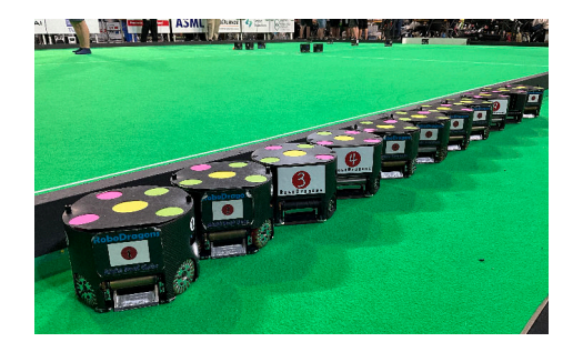
By introducing the eighth-generation (8G) robots last year, RoboDragons have been currently maintaining two generations for the competitions.
This paper provides two technical updates over the two generations that RoboDragons have developed between 2024 and 2025. In particular, the both updates relate controlling SSL robots. Section 2 describes the improvement of motor control by changing computation on the embedded system; Section 3 presents stabilizing motion control for dribbling.
Improvement of Motor Control
In 2024, RoboDragons have newly introduced the 8G robots [1]. One of the main changes between the 7G and 8G robots is to replace the processor in the embedded system. In the 7G robots, a combination of Renesas Electronics SH-2A [2] (as micro-controller unit (MCU)) and AMD (formerly Xilinx) Spartan 6 Field Programmable Gate Array (FPGA) [3] is used; AMD (formerly Xilinx) Zynq XC7Z7010-1CLG400 [4] is chosen as the System on Chip (SoC) in the 8G robots. As described in our ETDP2023 [7], RoboDragons adopt a two-layered (cascaded) control system and the role of the lower-layer controller implemented in the embedded system is to control angular velocity of motors driving omniwheels. Referring to the datasheet [2], the MCU has a floating-point unit (FPU) which can perform single/double-precision calculations. However, it was unavailable on the 7G robots due to any reason (the robot was out of control once trying to perform floating-point calculations), so computation on the embedded system had required fixed-point arithmetic instead. Introduction of the 8G robots equipped with the Zynq means that floating-point calculations can be performed on the embedded system. This section reports on its effectiveness based on an experimental result of motor control.
Scaling and Rounding in Fixed-Point Arithmetic
In fixed-point arithmetic, scaling is crucial to prevent overflow and underflow while ensuring computational accuracy. Scaling adjusts the bit allocation between the integer and fractional parts in order to keep numerical values within an appropriate range, which allows computational results to avoid lowering the precision as much as possible.
Now given an input data x. The bit width allocated for operations is described by the total word length $L_w$, with $L_{iw}$ and $L_{fw}$ representing the bit sizes allocated to the integer and fractional parts, respectively. Basically, the scaling factor is determined by $L_{fw}$ as follows:
$$L_{\text{fw}} = L_{\text{w}} - L_{\text{iw}} \qquad (L_{\text{iw}} := \lceil \log_2 |x| \rceil).$$
Data is scaled by bit shift operations with Eq. (1)—shifting the data one bit to the right halves the value while shifting one bit to the left doubles it. Also, if the number of fractional bits is insufficient, adjusting the scaling factor can improve the computational accuracy.
The well-known scaling method is Fixed-point progRammIng Design Environment (FRIDGE) [8], which provides scaling specialized for the addition, subtraction, and division. Consider two operands a and b where $|a| < |b|$. Then, the integer part $L_{iw}$ is defined as:
$$L_{\text{iw}} = \max \left{ \lceil \log_2 |a| \rceil + 1, \lfloor \log_2 |b| \rfloor + 1 + L_{gw} \right},$$
where $L_{gw}$ represents a guard bit. The guard bit set to 1 is an additional bit to statically prevent overflow. Based on the value of $L_{iw}$, the fractional part $L_{fw}$ is determined as:
$$L_{\text{fw}} = L_w - L_{\text{sign}} - L_{\text{iw}},$$
where $L_{sign}$ represents the sign bit, set to 1 for signed operations and 0 for unsigned operations. As for the multiplication, AUTOSCALER in C [9] defines $L_{iw}$ and $L_{fw}$ as follows:
$$L_{\text{iw}} = \lceil \log_2 |x| \rceil,$$
$$L_{\rm fw} = \frac{L_{\rm w}}{2} - L_{\rm iw} - L_{\rm sign},$$
where x is one of the operands. Furthermore, to prevent overflow in the subsequent operations, using a rounding function is useful. Reference [10] proposes to apply the following rounding function into a computational result p when shortening the word length:
$$m(p) := \frac{p + 2^{n-2}}{2^{n-1}}.$$
Experimental Evaluation
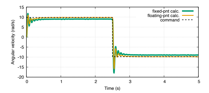
Focusing on controlling the angular velocity of motor driving omni-wheels, this subsection evaluates the performance differences between fixed-point and floating-point calculations.
Experimental Setup The controlled objects are brushless DC motors driving an omni-wheels of an 8G robot. In particular, the following custom-made motor units are adopted:
- Maxon Brushless DC motor: EC 45 flat (Part Number: 651610) [5]
- Maxon Inductive Encoder: Encoder MILE (Part Number: 673031) [6]
- (Custom made) motor shaft length: 8.7 mm
The main board connecting to them is equipped with the above-mentioned AMD (formerly Xilinx) Zynq XC7Z7010-1CLG400 that integrates a dual-core ARM Cortex-A9 processor. The lower-layer controller implemented on it acquires pulse values from the encoders attached motors and velocity commands via wireless communication; the control input is the Pulse Width Modulation (PWM) duty ratio that applies the corresponding voltage into the motor through the Field Effect Transistor (FET).
Table 1: Parameters of motor and wheel
| Symbol | Description | Value | Unit |
|---|---|---|---|
| $\beta_1 (= -\beta_4)$ | alignment angle of 1st (and 4th) wheel | $-(38/180)\pi$ | rad |
| $\beta_2(=-\beta_3)$ | alignment angle of 2nd (and 3rd) wheel | $-(142/180)\pi$ | rad |
| d | distance betw. wheel and robot's center | $7.88 \times 10^{-3}$ | m |
| $\eta$ | gear ratio | 64/21 | _ |
| J | inertia of motor with omni-wheel and gears | $1.35 \times 10^{-5}$ | $kg \cdot m^2$ |
| $\mathcal{B}$ | coefficient derived from viscous friction, back electromotive force (EMF) and so on | ||
| $K_{\tau}$ | torque constant | $29.5 \times 10^{-3}$ | Nm/A |
| R | terminal resistance phase to phase | 0.447 | Ω |
Before an experiment, the computer and robot have to be connected via two kinds of USB cables: a standard micro-A USB cable and a so-called Joint Test Action Group (JTAG) cable (more specifically, Xilinx Platform Cable USB II [11]). Then, by using AMD Vivado SDK 2019.1 [12] and the terminal emulator TeraTerm 5 [13], data can be logged at a frequency of 1 kHz during experiments.
Proportional-Integral Controller for Evaluation The definitions of various parameters are shown in Table 1. Velocity commands $(v_x^{\star}, v_y^{\star}, v_a^{\star})$ that the robot receives are converted into the motor angular velocity commands $\omega_{mi}^{\star}$ (i = 1, 2, 3, 4) as follows:
$$\begin{bmatrix} \omega_{m1}^{\star} \ \omega_{m2}^{\star} \ \omega_{m3}^{\star} \ \omega_{m4}^{\star} \end{bmatrix} = \frac{\eta}{\frac{d_w}{2}} \begin{bmatrix} \cos \beta_1 & \sin \beta_1 & -d \ \cos \beta_2 & \sin \beta_2 & -d \ \cos \beta_3 & -\sin \beta_3 & -d \ \cos \beta_4 & -\sin \beta_4 & -d \end{bmatrix} \begin{bmatrix} v_x^{\star} \ v_y^{\star} \ v_a^{\star} \end{bmatrix}.$$
In general, the dynamic model of the (brushless) DC motor with respect to the motor angular velocity $\omega_{mi}$ is formulated by
$$J\dot{\omega}{mi}(t) + \mathcal{B}i \omega{mi}(t) + \tau{\text{ext}i}(t) = K_{\text{PWM}} D_i(t),$$
where $K_{\text{PWM}} := K_{\tau} V_o/(200R)$, $V_o$ is the power supply voltage, $\tau_{\text{ext}i}$ and $D_i$ are an external force and a duty ratio to the i-th motor, respectively. Supposing this model and using $e_i := \omega_{mi}^{\star} - \omega_{mi}$, a Proportional-Integral (PI) controller to regulate $\omega_{mi}$ into $\omega_{mi}^{\star}$ can be designed as follows:
$$D_i(t) = \frac{J}{K_{\text{PWM}}} \left( K_P e_i(t) + K_I \int_0^t e_i(\tau) d\tau \right),$$
where $K_P$ and $K_I$ are the proportional and integral gains, respectively.
Stabilization of Forward Dribbling
Ball possession is known as one of the significant factors, at least, for the team performance in not only human but also robotic soccer games [14,15]. A typical skill contributing to ball possession is dribbling a ball. In the SSL, some research, developments, and technical challenges with respect to dribbling [16–19] have been proceeded. In particular, the recent advancement has been highly stimulated by an impact of the auto-centering dribble roller [20], by the ball placement rule [21] introduced since 2018, and by one of long term goals [22] established in 2020.
For ball placement, RoboDragons exploit diagonally kicking [23], passing, and forward/backward dribbling. Among those skills, forward dribbling tends to be unstabilized or failed. The cause may be that the ball obtains backspin from the dribbler simultaneously with getting forward spin from the ground. Motivated on this, RoboDragons have considered improving forward dribbling. A control method for stabilizing it is presented in this section.
Problem Setting
For simplicity, assume as follows:
- a desired trajectory for dribbling is a straight line;
- an SSL robot for dribbling can be controlled by velocity command $({}^{r}v_{x}, {}^{r}v_{y}, {}^{r}v_{a})$,
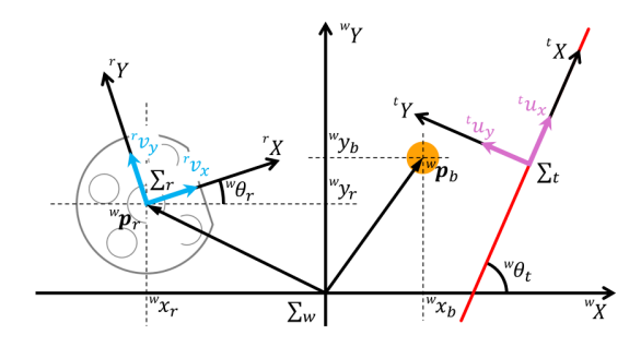
where variables used here base three kinds of frames: the world, robot, and trajectory frames as shown in Fig. 3 and Table 2. Giving an initial position ${}^{w}\mathbf{p}{s} = ({}^{w}x{s}, {}^{w}y_{s})$ and a terminal position ${}^{w}\mathbf{p}{f} = ({}^{w}x{f}, {}^{w}y_{f})$, the desired straight-line trajectory and its orientation on $\Sigma_{w}$ are defined as follows:
$${}^{w}y_{b}^{\star} - {}^{w}y_{s} = \frac{{}^{w}y_{f} - {}^{w}y_{s}}{{}^{w}x_{f} - {}^{w}x_{s}}({}^{w}x_{b}^{\star} - {}^{w}x_{s}),$$
$${}^{w}\theta_{t} = \operatorname{atan2}({}^{w}y_{f} - {}^{w}y_{s}, {}^{w}x_{f} - {}^{w}x_{s}).$$
Then, as a stabilizing problem for forward dribbling, consider how to control the SSL robot so as to dribble a ball forward on the desired trajectory even if the ball is away from the trajectory.
Table 2: Definition of frames and variables. Every frame is a right-handed coordinate system.
| Symbol | Description |
|---|---|
| $\Sigma_w$ | World frame |
| $\Sigma_r$ | Robot frame (the positive direction of x-axis points to the robot's front) |
| $\Sigma_t$ | Desired trajectory frame (the positive direction of x-axis points to the traveling direction) |
| $({}^{w}x_b, {}^{w}y_b)$ | Coordinates of ball's center on $\Sigma_w$ |
| $({}^{w}x_r, {}^{w}y_r)$ | Coordinates of robot's center on $\Sigma_w$ |
| ${}^{w}\theta_r$ | Orientation of $\Sigma_r$ on $\Sigma_w$ |
| $({}^{w}x_t, {}^{w}y_t)$ | Coordinates of $\Sigma_t$ on $\Sigma_w$ |
| ${}^{w}\theta_t$ | Orientation of $\Sigma_t$ on $\Sigma_w$ |
| $({}^{r}v_x, {}^{r}v_y)$ | Translational velocity of $\Sigma_r$ on its frame |
| $({}^{t}u_x, {}^{t}u_y)$ | Translational velocity of $\Sigma_t$ on its frame |
Proposed Control Method for Stabilizing Forward Dribbling
Our basic idea to solve the problem is to determine the velocity command by proportional control based on the distance between the desired trajectory and ball. In particular, its point is to exploit an intermediate position behind the ball for pushing into the trajectory. So, our proposed control method for stabilizing forward dribbling is divided into two phases: the first is to drive the robot to the intermediate position and then the second is to push forward the ball so as to put it on the desired trajectory smoothly. Hereafter, for design easiness, handle $\Sigma_t$ $\boldsymbol{u} = [{}^t!u_x, {}^t!u_y, {}^t!u_a]^{\top}$ instead of $\boldsymbol{v} = [{}^r!v_x, {}^r!v_y, {}^r!v_a]^{\top}$ as the velocity command. Note that $\boldsymbol{u}$ is related to V as follows:
$$\boldsymbol{v} = \boldsymbol{R}_a({}^{\boldsymbol{w}}\boldsymbol{\theta}_r - {}^{\boldsymbol{w}}\boldsymbol{\theta}_t),\boldsymbol{u},$$
where
$$\boldsymbol{R}_a(\theta) = \begin{bmatrix} \cos \theta & -\sin \theta & 0\ \sin \theta & \cos \theta & 0\ 0 & 0 & 1 \end{bmatrix}.$$
A controller to realize the above-mentioned control method can be designed as follows:
$$^t u_x = {^t} u_x^{\star},$$
$${}^{t}u_{y} = \begin{cases} K_{yb} , \varepsilon_{yb}, & \text{if } |\varepsilon_{a}| < \delta_{\theta}, \ K_{yr} , \varepsilon_{yr}, & \text{otherwise,} \end{cases}$$
$$^{t}u_{a} = K_{a}\varepsilon_{a},$$
where $K_{yb}$, $K_{yr}$, and $K_a$ are proportional feedback gains and $\delta_{\theta}$ is a threshold for switching the control phases. The command ${}^tu_x$ is feedforwardly controlled by giving an appropriate desired velocity ${}^tu_x^{\star}$. As for designing ${}^tu_y$ and ${}^tu_a$, errors $\varepsilon_{yb}$, $\varepsilon_{yr}$, and $\varepsilon_a$ are used. Those derivations are a bit complicated, so the details are individually described in the following paragraphs.
Derivation of $\varepsilon_{yb}$ and $\varepsilon_a$ The error $\varepsilon_{yb}$ is the distance along the ${}^ty$-axis on $\Sigma_t$. Using the orthonormal basis ${}^te_y$ on ${}^ty$-axis, $\varepsilon_{yb}$ is represented as
$$\varepsilon_{yb} = {}^{t}\boldsymbol{e}{y}^{\mathsf{T}}({}^{w}\boldsymbol{p}{t} - {}^{w}\boldsymbol{p}_{b}),$$
where ${}^{w}\boldsymbol{p}{t} := [{}^{w}x{t}, {}^{w}y_{t}]^{\top}$ and ${}^{w}\boldsymbol{p}{b} := [{}^{w}x{b}, {}^{w}y_{b}]^{\top}$. On the other hand, letting ${}^{w}\phi^{\star}$ be a desired pushing angle on $\Sigma_{w}$, the error $\varepsilon_{a}$ can be determined as
$$\varepsilon_a = {}^{w}!\phi^* - {}^{w}!\theta_r.$$
Introducing ${}^t!\phi$ as a desired pushing angle on $\Sigma_t$, ${}^w!\phi^{\star}$ is set as
$${}^{w}\phi^{\star} = {}^{w}\theta_{t} + {}^{t}\phi,$$
which is validated by the geometric relationship as shown in Fig. 4. Here, so as to minimize $\varepsilon_{yb}$, the authors design ${}^t!\phi$ as follows:
$$^{t}\phi = -K_{\phi}\varepsilon_{yb},$$
where $K_{\phi}$ is a proportional feedback gain.
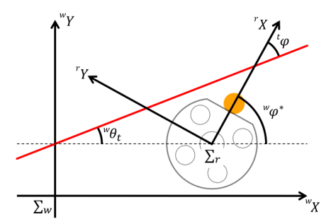
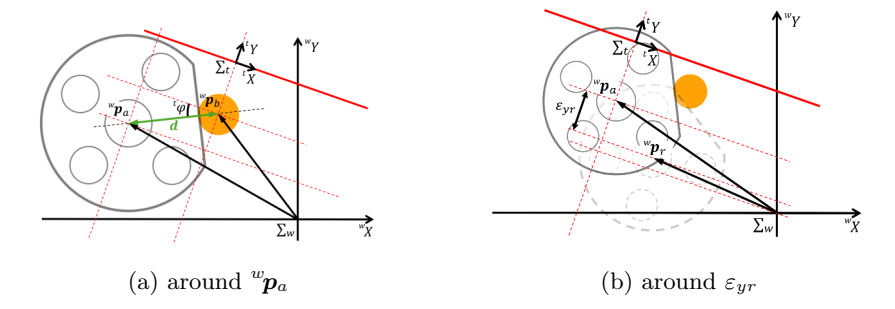
Table 3: Relationship between mode and condition.
| mode | conditions |
|---|---|
| 0 | $\varepsilon_a < \delta_{\theta}$ |
| 1a | $\varepsilon_a \ge \delta_\theta$ and $\varepsilon_{yb} < 0.2$ |
| 1b | $\varepsilon_a \ge \delta_\theta$ and $\varepsilon_{yb} \ge 0.2$ |
Experimental Result
An experiment was conducted under the following parameters:
$${}^{w}\mathbf{p}{s} = [-4.5 ,\mathrm{m}, -2.0 ,\mathrm{m}]^{\top}, \quad {}^{w}\mathbf{p}{f} = [1.5 ,\mathrm{m}, -2.0 ,\mathrm{m}]^{\top},$$
$$K_{\phi} = 1.96, \quad d = 0.78 ,\mathrm{m}, \quad K_{yb} = 1.0, \quad \delta_{\theta} = 0.2 ,\mathrm{rad},$$
$$(K_{yr}, K_{a}) = \begin{cases} (5.0, 0.52) & \text{if } |\varepsilon_{yb}| < 0.2, \ (3.33, 0.79) & \text{otherwise,} \end{cases},$$
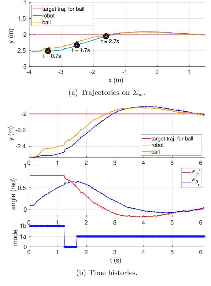
At t=0, the robot rested at its position $({}^w x_r, {}^w y_r) = (-4.5 ,\mathrm{m}, -2.5 ,\mathrm{m})$ and orientation ${}^w \theta_r = 0.0 ,\mathrm{rad}$. The ball was set against the middle of the dribble roller. The experimental result is shown in Fig. 6. Figure 6 (a) depicts the desired and actual trajectories on $\Sigma_w$; figure 6 (b) represents time histories of angles on $\Sigma_w$, y-coordinates on $\Sigma_w$, and mode, where the parameter mode stands for the conditions as described in Table 3. From Figs. 6 (a) and (b), it can be found that the robot was always positioned a bit behind the ball so as to push it forward towards the desired trajectory. On the other hand, it can be observed that the ball widely behaved at the moment that the mode transitioned. Improving behavior such transition is one of future works.
Concluding Remarks
In this paper, the technical updates of RoboDragons 2024–2025 has been shared. The contents are divided into two parts: the first is about the performance improvement of motor control by enabling floating-point calculations in the embedded system and the second is about stabilization of forward dribbling by introducing feedback control.
Acknowledgement
This work was partially supported by JSPS KAKENHI Grant Number 23K11338 and Aichi Prefectural University Alumni Association. The authors would like to thank Yamashita, S. and Matsubara, H. (e-Valley, Co. Ltd., Japan) for their technical support. The authors also would like to thank Prof. Nakashima, A. (Nanzan University, Japan) for his helpful and constructive discussion on Section 3. Furthermore, the authors would like to thank the other active RoboDragons 2024–2025 members—Nomura, H., Wakayama, T., Tachi, K., Tanaka, K., Agatsuma, S., Sugiura, K., Fujita, S., Suzuki, T., Honobu, K., Miyazaki, Y., Mori, K., Iguchi, K., Kato, A., Kawata, J., Shiomi, R., Nakayama, R., Noji, T., Fujita, H., Yuge, H., Asano, T., Kusakabe, M., Saijo, N., Suzuki, M., Takemi, S., Terao, R., Iwata, T., Iwamoto, M., Kako, H., Kataoka, K., Kawata, K., Sasaki, R., Matsugaki, S., and Mochizuki, M.—for their support.
References
- Fujita, S. and Ito, M.: "RoboDragons 2024 extended team description," RoboCup Soccer Small Size League, 2024. Available online: https://ssl.robocup.org/wp-content/uploads/2024/04/2024_ETDP_RoboDragons.pdf
- Renesas Electronics: "SH7214 Group, SH7216 Group," User's Manual: Hardware, Rev.4.00, Jun 2013. Available online: https://www.renesas.com/en/document/mah/sh7214-group-sh7216-group-users-manual-hardware?srsltid=AfmBOopc58bCPhhHqukbUG3RRQVT-vjFu0MfIJdLzJJFkv0YW4YxW71T (accessed on 9 Feb 2025).
- AMD: "Xilinx Spartan-6 FPGA Data Sheet: DC and AC switching Characteristics," Product Specification, DS162 (v3.1.1), Jan 2015. Available online: https://docs.amd.com/v/u/en-US/ds162 (accessed on 9 Feb 2025).
- AMD: "Xilinx Zynq-7000 SoC (Z-7007S, Z-7012S, Z-7014S, Z-7010, Z-7015, and Z-7020): DC and AC switching Characteristics," Product Specification, DS187 (v1.21), Dec 2020. Available online: https://docs.amd.com/v/u/en-US/ds187-XC7Z010-XC7Z020-Data-Sheet (accessed on 9 Feb 2025).
- Maxon: "EC 45 flat φ 43.5 mm, brushless, 50 watt," V2 with Hall sensors and cables, Part Number: 651610, Mar 2021. Available online: https://www.maxongroup.com/medias/sys_master/root/8882562990110/EN-21-296.pdf (accessed on 11 Feb 2025).
- Maxon: "Encoder MILE, 2048 cpt, 2-channel, with line driver," Part Number: 673031, Mar 2021 Available online: https://www.maxongroup.com/medias/sys_master/root/8883954745374/EN-21-460-461.pdf (accessed on 11 Feb 2025).
- Ito, M., Shibata, M., Agatsuma, S., Ando, Y., and Fujita, S.: "RoboDragons 2023 extended team description," RoboCup Soccer Small Size League, 2023. Available online: https://ssl.robocup.org/wp-content/uploads/2024/02/rd-etdp23fin-v2-5.pdf
- Keding, H., Willems, M., Coors, M., and Meyr, H.: "FRIDGE: a fixed-point design and simulation environment," Proceedings Design, Automation and Test in Europe, pp. 429–435, 1998. https://doi.org/10.1109/DATE.1998.655893
- Kum, K., Kang, J., and Sung, W.: "AUTOSCALER for C: an optimizing floating-point to integer C program converter for fixed-point digital signal processors," IEEE Transactions on Circuits and Systems II: Analog and Digital Signal Processing, Vol. 47, No. 9, pp. 840–848, 2000. https://doi.org/10.1109/82.868453
- Aoki, T.: "Implementation Methodology of Control Algorithms for Fixed-Point Microprocessors (1st Report)," Journal of the Society of Precision Engineering, Vol. 71, No. 3, pp. 394–398, 2005 (in Japanese). https://doi.org/10.2493/jspe.71.394
- AMD: "Xilinx Platform Cable USB II," DS593 (v1.5.1), Aug 2018. Available online: https://docs.amd.com/v/u/en-US/ds593 (accessed on 11 Feb 2025).
- AMD: "Xilinx Software Development Kit (SDK) User Guide: System Performance Analysis," UG1145 (v2019.1), May 2019. Available online: https://docs.amd.com/v/u/2019.1-English/ug1145-sdk-system-performance (accessed on 11 Feb 2025).
- Tera Term Project: "Tera Term 5," Nov 2024. Available online: https://teratermproject.github.io/index-en.html (accessed on 11 Feb 2025).
- Wang, S., Qin, Y., Jia, Y., and Igor, K.E.: "A systematic review about the performance indicators related to ball possession," PLOS ONE, 17(3): e0265540, 2022. https://doi.org/10.1371/journal.pone.0265540
- Abreu, M, Reis, L.P., and Lau, N.: "Designing a skilled soccer team for RoboCup: exploring skill-set-primitives through reinforcement learning," arXiv, cs.RO, Dec 2023. https://doi.org/10.48550/arXiv.2312.14360
- Cooksey, P., Mendoza, J.P., Veloso, M.: "Opponent-aware ball-manipulation skills for an autonomous soccer robot," In: Behnke, S., Sheh, R., Sarıel, S., Lee, D. (eds) RoboCup 2016: Robot World Cup XX. RoboCup 2016. Lecture Notes in Computer Science, Vol. 9776. Springer, Cham. 2017. https://doi.org/10.1007/978-3-319-68792-6_7
- Ommer, N., Ryll, A., Ratzel, M., and Geiger, M.: "TIGERs Mannheim Extended team description for RoboCup 2024," RoboCup Soccer Small Size League, 2024. Available online: https://ssl.robocup.org/wp-content/uploads/2024/04/2024_ETDP_TIGERsMannheim.pdf
- RoboCup Soccer Small Size League Technical Committee: "Challenge 3: Dribbling," In RoboCup Small Size League (SSL) Hardware Challenge 2021, Jun 2021. Available online: https://robocup-ssl.github.io/ssl-hardware-challenge-rules/rules.html#_challenge_3_dribbling (accessed on 11 Feb 2025)
- RoboCup Soccer Small Size League Technical Committee: "RoboCup 2022 SSL Dribbling Challenge Rules," Jun 2022. Available online: https://robocup-ssl.github.io/technical-challenge-rules/2022-ssl-dribble-rules.html (accessed on 11 Feb 2025)
- Yoshimoto, T., Horii, T., Mizutani, S., Iwauchi, Y., Yamada, Y., Baba, K, and Zenji. S.: "OP-AmP 2017 team description paper," RoboCup Soccer Small Size League, 2017. Available online: https://ssl.robocup.org/wp-content/uploads/2019/01/2017_TDP_Op-Amp.pdf
- RoboCup Soccer Small Size League Technical Committee: "Ball Placement," In Rules of the RoboCup Small Size League, May 2024. Available online: https://robocup-ssl.github.io/ssl-rules/2024/sslrules.html#_ball_placement (accessed on 11 Feb 2025)
- RoboCup Soccer Small Size League: "More dexterous ball manipulation," In Guiding Principles and Long Term Goals of the Small Size League, Dec 2020. Available online: https://robocup-ssl.github.io/ssl-goals/sslgoals.html#_more_dexterous_ball_manipulation (accessed on 11 Feb 2025)
- Ito, M., Suzuki, R., Isokawa, S., Du, J., Suzuki, R., Nakayama, M., Ando, Y., Umeda, Y., Ono, Y., Kashiwamori, F., Kishi, F., Ban, K., Yamada, T., Adachi, Y., and Naruse, T.: "RoboDragons 2019 extended team description," RoboCup Soccer Small Size League, 2019. Available online: https://ssl.robocup.org/wp-content/uploads/2019/03/2019_ETDP_RoboDragons.pdf (accessed on 11 Feb 2025).