RoboFEI 2025 Team Description Paper
Alexandre A. Leme, Alvaro D. Neto, Caio Henrique de O. Fonseca, Felipe Estevão C. de Mello, Giovanna Cecilia S. Quaresma, Guilherme Luis Pauli, Henrique B. Simões, João Victor L. Aguiar, Leonardo C. Nogueira, Matheus E. de S. N. Chiari, Sophia S. M. Sanches, Prof. Danilo H. Perico, Prof. Flavio Tonidandel, Prof. Reinaldo A. C. Bianchi, Prof. Plinio T. Aquino Jr
Robotics and Artificial Intelligence Laboratory Centro Universitário da FEI, São Bernardo do Campo, Brazil
Abstract This paper presents the current state of the RoboFEI Small Size League team as it stands for RoboCup International Small Size League competition 2025, in Salvador, Brazil. The paper contains descriptions of mechanical design, electronic circuits and software improvements.
Introduction
During our last RoboCup, we noticed a few issues with the robot's hardware. We realized that our motors were not operating at their maximum efficiency, indicating that improvements could be made in terms of torque, speed, and control. Additionally, since adopting robot generation v2012.2 for mechanics and implementing the modular concept for electronics our team has faced challenges with the placement, design, functionality, and assembly methods of some mechanical parts and electronic components.
Regarding software, the team has developed notable improvements on the positioning system, but the decision making process remains the same as last year's. For RoboCup 2025, RoboFEI will present a new motor transmission system and control methods, along with updated versions of our mechanical structure and electronic boards. We expect these changes to significantly enhance our robot's performance during SSL matches.
Mechanics
In recent years, the RoboFEI team's robots have shown that the motors, which are a major part of our budget, are not being used to their full potential. To fix this issue, we decided to enhance the mouting blocks and transmission assemblies, allowing the motors to work more efficiently, which will improve the robot's speed and accuracy. Additionally, the current placement of the encoders takes up a lot of space on the robot's base. By optimizing their layout, we are capable of creating more room for other essential components, like the kicking system, capacitors, and support rods.
To tackle these space and performance problems, we decided to change the angle of the rear mounting blocks from 33° to 45°. We also proposed redesigning these mounting blocks to include mounted encoders, which will connect directly to the wheel. This new design is expected to lower the torque needed from the motors and boost the overall speed of the robot.
Introducing Robot Generation v2025
Direct drive is essentially an electric drive in which no reduction gear is used. In this setup, the electric motor's rotor connects directly to the load, which removes the need for any mechanical gears [1]. To implement direct drive in the Small Size League (SSL) robot models, it is needed to adjust the mounting blocks due the current height of the motor compared to the internal gearing that links it to the wheel. This height is important as in consequence of the existing 3:1 reduction gearing and encoders position in the robot's base.
Encoders are devices that convert the motor's position into a digital signal. In our robot, they work alongside the Hall effect sensors embedded on the Maxon EC-45 motors, which help determine the motor's position by detecting magnetic fields. This combination allows an accurate control, giving the right current to each motor phase to produce torque.
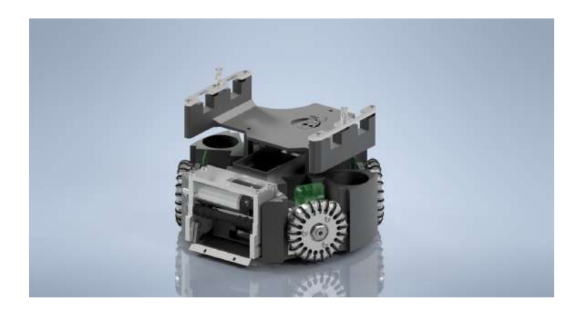
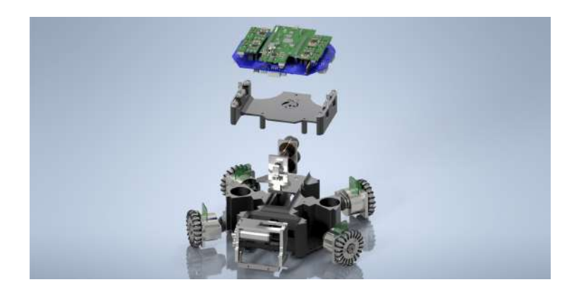
To improve overall performance, consistency, and durability, we've made several optimizations. These changes are aimed at enhancing performance during matches, making machining processes simpler, meeting technical specifications, and increasing the lifespan of both the components and the robot itself. The new base design removes the need for lower supports and reduces body vibrations by being made as a solid 3D-printed block. It also has space for capacitors, a battery, and supports for electronic components, as well as a new activation module. Fig.1 shows the robot's assembly in Inventor 2024 ®, where it's possible to see all changes made in the last year. Meanwhile in Fig.2 it's possible to see the exploded view of the robot's assembly, detaching each robot's system for a better understading.
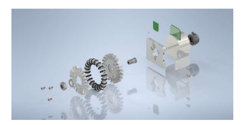
To replace the current 3:1 spur gear transmission system, it was designed a motor coupling component to drive the wheel directly (Direct Drive), inspired by TIGERs Mannheim design [2]. This component is fitted onto the motor shaft using an H7 standard interference fit and adhesive bonding. Fig.3 shows the complete project of the new transmission module. In the image it's possible to see mechanical assembly for two types of encoders: US DIGITAL E4T-1000-157-S-H-M-B (or AS5600) and iC-PX2604 (Sensor) and PX01S (Disc). The parallel use of both encoders isn't possible with current electronics, but it's being considered by the team.
For performance testing, RoboFEI created a one-square-meter path using our own software, with the start and end at the same point. During the testing process, we gathered position and speed data from the new robot in a real-world setting. The robot had to navigate the specific path on the field, using cameras for detection and movement, just like it would in an actual match.
We used the RoboFEI's current 2023 model [3] as a reference to compare with the new version. This method provided a straightforward way to show the differences in performance between the two models, helping to justify the proposed changes.
The current robot, built mainly from a 6000-series aluminum alloy, weighs 2.726 kilograms and can reach a wheel speed of about 495 RPM. In contrast, the new robot is primarily constructed from ABS, weighs 1.568 kilograms, and can achieve a wheel speed of around 1590 RPM.
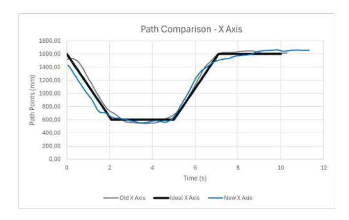
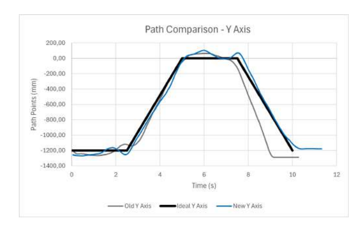
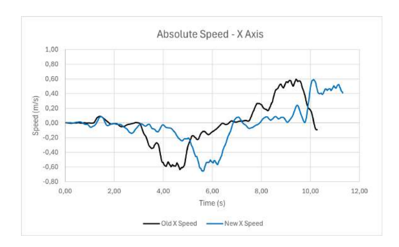
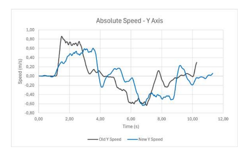
During field testing, we focused on two important metrics: positional accuracy and trajectory velocity. The current robot had an average trajectory deviation of 116.38% on the Y-axis and 50.86% on the X-axis, with maximum velocities of 0.86 m/s on the Y-axis and 0.6 m/s on the X-axis. The new robot showed better precision on the Y-axis, averaging an error of 52.26%, but had a slightly higher error of 66.96% on the X-axis. Its maximum velocities were 0.60 m/s on the Y-axis and 0.59 m/s on the X-axis.
A comparison between the robots v2012.2 and v2025 paths, as well as their velocities over time, for each axis, can be seen below. The graphic in Fig.4 shows the X axis paths of the new robot and the old robot compared to the ideal path, while Fig.5 compares the paths on the Y axis. At the same time, the graph in Fig.6 compares the two robots' velocities on the X axis and Fig.7 does the same for the Y axis.
An analysis of the data reveals that the new robot's movement pattern is quite different from the current model. Even though the control system for this updated robot hasn't been fully optimized for its new gearbox and wheel setup, it can still reach speeds similar to the existing robot while showing less error. This indicates strong performance and suggests it's ready for official matches and further testing.
Looking ahead, RoboFEI mechanics team will revise the structural design and consider higher RPM to create a better motion control model.
Robot Specifications
| Specification | Robot version v2012.2 | v2025 |
|---|---|---|
| Dimension | Ø179 x 150mm | Ø180 x 150mm |
| Total weight | 3.0 kg | 1.6 kg |
| Driving motors | Maxon EC-flat-45 50W 18V | Maxon EC-flat-45 50W 18V |
| Gear | 3:1 | 1:1 |
| Gear type | Internal Spur | Direct Drive |
| Wheel diameter | 54mm | 54mm |
| Encoder | US DIGITAL E4T-1000-157-S-H-M-B | AS5600 |
| Dribbling motor | Maxon EC-max-22 25W 18V | Maxon EC-max-22 25W 18V |
| Dribbling gear | 7:3 | 1:1:1 |
| ø Dribbling bar | 16 mm | 9.5 mm |
| Kicker charge | 2x 1000µF @ 200V | 2x 1000µF @ 200V |
| Straight kick speed | higher than 6,5 m/s | higher than 6,5 m/s |
| Microcontroller | STM 32F411 | STM 32F411 |
| Sensors | Encoders, Gyroscope, Accelerometer | Encoders, Gyroscope, Accelerometer |
| Communication link | nRF24L01 transceiver, 2 Mbps, 2.4/2.5 GHz | nRF24L01 transceiver, 2 Mbps, 2.4/2.5 GHz |
| Power Supply | Li-Po Battery, 11.1 V nominal, 2200mAh | Li-Po Battery, 11.1 V nominal, 2200mAh |
Electronics
In recent years, RoboFEI has adopted a modular concept in electronics, utilizing the commercial Electronic Speed Controller (ESC) STM B-G431B-ESC1 as our motor controller.
Motor Control Board
In recent years, RoboFEI has adopted a modular concept in electronics [3], utilizing the commercial Electronic Speed Controller (ESC) STM B-G431B-ESC1 as our motor controller. This ESC is connected to the robot's main board via an adapter board that we developed. However, we encountered several issues with its use and functionality.
Firstly, physically assembling the ESC onto the adapter board was challenging, and the soldered wires proved to be fragile due to their positioning. Additionally, we observed that using this controller resulted in the motors not delivering the desired torque. We also faced difficulties in refining motor control and lacked the ability to modify the circuit as needed.
Our electronics team reached out to the STMicroelectronics support team to find a solution for our issues. We were advised not to rely on the B-G431B-ESC1 controller for our requirements, as it is designed for low-torque, high-speed applications, primarily used in drones. Consequently, we decided to design a new motor driving circuit that uses a dedicated Integrated Circuit (IC) tailored to the robot's needs.
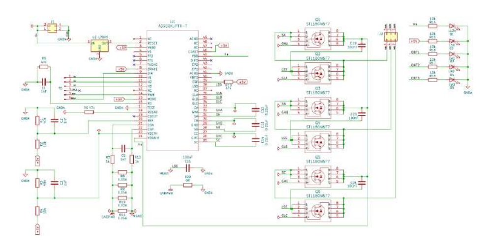
For that purpose, RoboFEI has chosen the A3930 integrated circuit [4], which is specifically designed for controlling 3-phase BLDC motors. This circuit is commonly used in our league [5,6] and offers valuable features. TIGERs Mannheim, for example, doesn't use A3930 for their motor controller anymore, but they recommend begginer teams to use it due to its simplicity. For the first prototype, we selected the STL180N6F7 N-channel MOSFET to handle the high current in the three-phase gate drive. This MOSFET is the same one used in the B-G431B-ESC1 gate drive and is well-suited for the A3930 application.
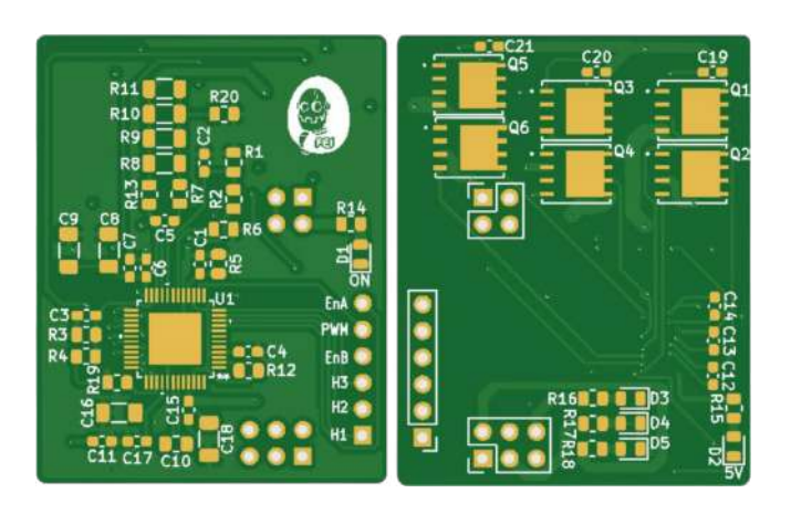
The circuit requires some further adjustments to optimize the capabilities of the A3930, such as its torque control, current limiting and operation modes. However, the first prototype has demonstrated good functionality as a PWM 3 phase motor controller for the Maxon EC 45. The complete schematic is shown in Fig.8, along with the printed circuit board layout, designed to match our main board pinout, in Fig.9.
Magnetic Encoder
At the same time as the new motor control board has been designed, we kept developing ways to improve the motor's control, still using the STM ESC but with a different type of encoder and control method. Therefore, this year, we chose to use the magnetic encoder AS5600 instead of our previous optical encoder E4T, a USDigital model with 1000 pulses for revolution. RoboFEI has experienced some issues with the optical encoder because we had to install it manually into the robot. It often provided incorrect readings, likely due to its positioning or the vibrations while the robot was in motion. Additionally, it tended to accumulate dirt over time. Therefore, using the AS5600 [7] was a better option due to its facility to align the magnet in the center of the Nanotech motor DF45L024048-A2 to run some tests.
The encoder reading was made by using the SimpleFOC library [8] ran in an Arduino NANO, and once the data was collected from the AS5600, we had to make a moving average to stabilize the data because it was too noisy at first sight. Then the values were sent to the main STM B-G431B-ESC1 motor driver through UART communication, due to the ESC's lack of I2C inputs.
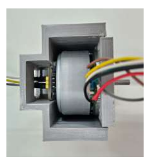
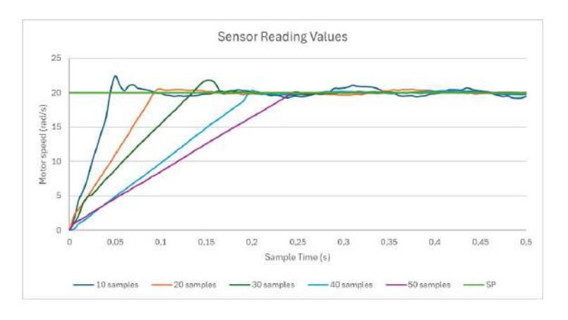
Afterward, we went back to using the SimpleFOC library to make the motor move with an open loop code and set a convenient setpoint, in order to see the response of the sensor. The analysis was made by taking data into 5 milliseconds of delay between each value, setting the speed in the code to 20 rad/s and using a dataset of 100 values from each calibration curve. In Fig.10 it is possible to see the motor being used with the magnetic encoder, fitted into a 3D printed support, designed for testing it. A graphic, shown in Fig.11, was built to evaluate the response time of the sensor for a different number of samples.
After creating the graphic, it's clear that the rise time increases as the number of samples increases. We decided to use a moving average with 15 values to ensure the robot's reaction time is fast while minimizing noise. Moving forward, it is essential to integrate the sensor readings into the firmware to enhance the robot's PID control in the future.
Kicker Board
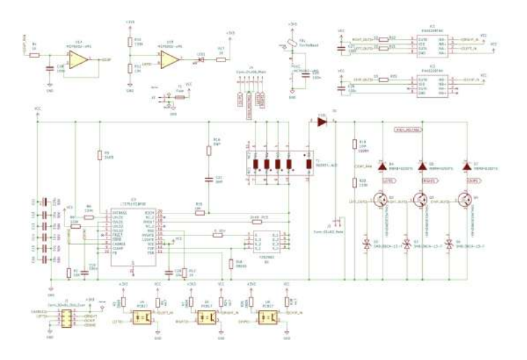
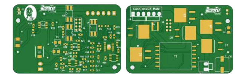
For the kicker board circuit, RoboFEI is conducting tests to transition from a buck converter to a flyback charging system using the LT3751 integrated circuit [9]. A new circuit has been developed based on the example uses from TIGERs Mannheim [2] and RobôCIn to accelerate the capacitor charging process. Currently, the kicker board takes about 40 seconds to reach its maximum charge, while the flyback circuit is expected to achieve a similar voltage in approximately just 3 seconds.
The rapid charging of the capacitor allows robots to kick with more power and in shorter intervals between kicks, making the game more dynamic and enhancing both our attacking and defensive plays. The schematic of the complete circuit, including the charging and activating sections, can be seen in Fig.12, along with the PCB design in Fig.13.
Software
The software improvements for RoboCup 2025 focus on advanced positioning strategies and sensor integration to enhance the team's competitive performance.
Finding Pass Positioning
In this section, we describe the strategy used to determine the optimal position of the pass receiver in a soccer game, inspired by the concepts of the 'Repulsive Pass Receiver' and 'Repulsive Attacker' as described by the 2022 RoboCup Champion TIGERs Mannheim Team [10].
Defining the potential forces: The field is discretized to create a matrix, where each cell contains a potential value. This value is adjusted based on the behavior of the robots and the ball in the field, ensuring that the best cells for placing a robot correspond to the lowest potential values. The following describes the forces involved and how to calculate them:
- Repulsive Force of the Ball (Fr(b)): A repulsive force is applied based on the ball's position and the various points on the field. This prevents the receiver from positioning themselves too close to the ball.
- Repulsive Force of Opponents (Fr(a)): Multiple repulsive forces are applied at each point on the field, depending on the positions of opposing robots. This helps prevent collisions and interference during passing.
- Repulsive Force of Disinterest Positions (Fr(dp)): An additional repulsive force is applied to keep the robots away from undesirable positions on the field, such as the area near their ally's goal.
- Attractive Force for Strategic Positions (Fa(sp)): An attractive force is applied to guide the robots to strategic positions on the opponent's defensive side.
Ideal positioning: The calculation consists of either a repulsive force (Equation 1) or an attractive force (Equation 2). The variable Va represents an adaptive value, and d is the distance between the cell point and the object (which could be a ball, robot, or either unwanted or desired points). The final potential value for each cell is determined by Equation 3, while the Ideal Position (IP) is defined by Equation 4, which selects the point of maximum potential.
$$Fr(a,b,dp) = \frac{Va}{d^2}$$ (1)
$$Fa(sp) = \frac{Va}{d^2}$$ (2)
$$V(p) = Fa - (Fr(a) + Fr(b) + Fr(dp))$$ (3)
$$IP = max(V(p))$$ (4)
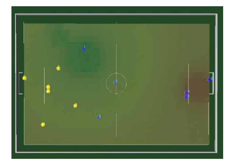
Simulated Results: This modification was effective as it ensured that the robots avoided non-strategic positions and maintained an appropriate balance between keeping a safe distance from opponents and staying close to the ball. The ideal positioning is calculated dynamically, adapting to changes in the field configuration throughout the game. To illustrate this, we present Fig.14, that shows the actual positioning of the robots and the ball in the grSim simulator. It also includes a heat map based on the potential field, highlighting areas of low interest. On the figure, the greener the area, the higher the potential of the point; the redder, the lower the potential of the point.
The complete source code implementation can be found on the RoboFEI GitLab Repository [11], along with open-source hardware and firmware.
Conclusion
In conclusion, the planned improvements, such as the new motor controller, the kicking system, the magnetic encoder, and the new robot mechanical design, are expected to enhance the robot's ingame perfomance with improved hardware, assisted the by the new positioning strategies in the software, that could enable better passing in defined plays.
Acknowledgements
We would like to thank, in advance, the Small Size League Committee, for the consideration of our material. We would also like to immensely thank the staff of Centro Universitário FEI, for all the help we always received from them.
References
- RoboCup-SSL. Principles and goals. https://ssl.robocup.org/principles-andgoals/, 2025. [Online; accessed 5-Fev-2024].
- Andre Ryll, Nicolai Ommer, Mark Geiger, Malte Jauer, and Julian Theis. Tigers mannheim extended team description for robocup 2020. 2020.
- Alvaro D. Neto, Andre L. Marques, Bruno B. Correa, Felipe E. C. de Mello, Guilherme M. R. Kashihara, Guilherme W. Cardoso, Henrique B. Simoes, Joao V. L. Aguiar, Leonardo da S. Costa, Nityananda V. Saraswati, Rafael M. Cukier, Thiago O. Aravena, Flavio Tonidandel, Plinio T. A. Junior, and Reinaldo A. C. Bianchi. Robofei 2023 team description paper. 2023.
- Allegro MicroSystems. Automotive 3-Phase BLDC Controller and MOSFET Driver, 9 2021. Rev. 7.
- Andre Ryll, Mark Geiger, Nicolai Ommer, Arne Sachtler, and Lukas Magel. Tigers mannheim extended team description for robocup 2016, 2016.
- Cecília Silva, Charles Alves, Felipe Martins, Joao Gabriel Machado, Juliana Damurie, Lucas Cavalcanti, Matheus Vinícius, Renato Sousa, Riei Rodrigues, Roberto Fernandes, et al. RobôCIn 2020 team description paper, 2020.
- ams. 12-bit Programmable Contactless Potentiometer, 8 2014. Rev. 1.
- Arduino simple field oriented control (foc) project. https://docs.simplefoc.com/. Accessed: 2025-02-08.
- Linear Technology. High Voltage Capacitor Charger Controller with Regulation, 6 2012. Rev. C.
- Mark Geiger, Nicolai Ommer, and Andre Ryll. Robocup 2022 SSL champion tigers mannheim - ball-centric dynamic pass-and-score patterns. In Amy Eguchi, Nuno Lau, Maike Paetzel-Prüsmann, and Thanapat Wanichanon, editors, RoboCup 2022: Robot World Cup XXV [Bangkok, Thailand, July 11-17, 2022], volume 13561 of Lecture Notes in Computer Science, pages 276–286. Springer, 2022.
- RoboFEI-SSL. Robofei small size league gitlab. https://gitlab.com/robofei/ssl, 2021. [Online; accessed 1-Fev-2024].