RoboJackets 2025 Team Description Paper
Saihari Kota, Sid Parikh, Jack Sherling, Nathaniel Wert, Kelvin Hau, Krish Mittal
Georgia Institute of Technology
Abstract This paper describes the improvements implemented by the Georgia Institute of Technology's RoboCup SSL team, RoboJackets, in preparation to compete in RoboCup 2025 in Salvador, Brazil. This year, our main focus was on improving our motion driving system by designing and producing new motor and control boards. Mechanical modifications were limited this year and mainly centered around a shell and color plate redesign. Firmware updates built on progress from last year's rewrite to improve debugging and the motion update rate. Software development this year was centered around complying with rules and improving basic skills such as ball collection as well as kick/path planning. As always, all of our designs and code are open-sourced. See the RoboCup SSL website for links, or search for "RoboCup" on our GitHub page.
Mechanical
This section describes the mechanical improvements and design changes implemented by RoboJackets for the 2025 season.
Shell Redesign
This year, mechanical efforts for our fleet of robots were limited due to lack of budget and manpower. As such, we worked on continuing and finishing mechanical projects that we started last year and to maintain our current electrical stack. Our main gripe with the mechanical design during last year's competition was the state of our shells and color plates. Since, this is a cost effective and relatively simple change, this was main point of focus for the mechanical team. Outside of this, we worked on ensuring that our robots had reliable hardware for all other subsystems.
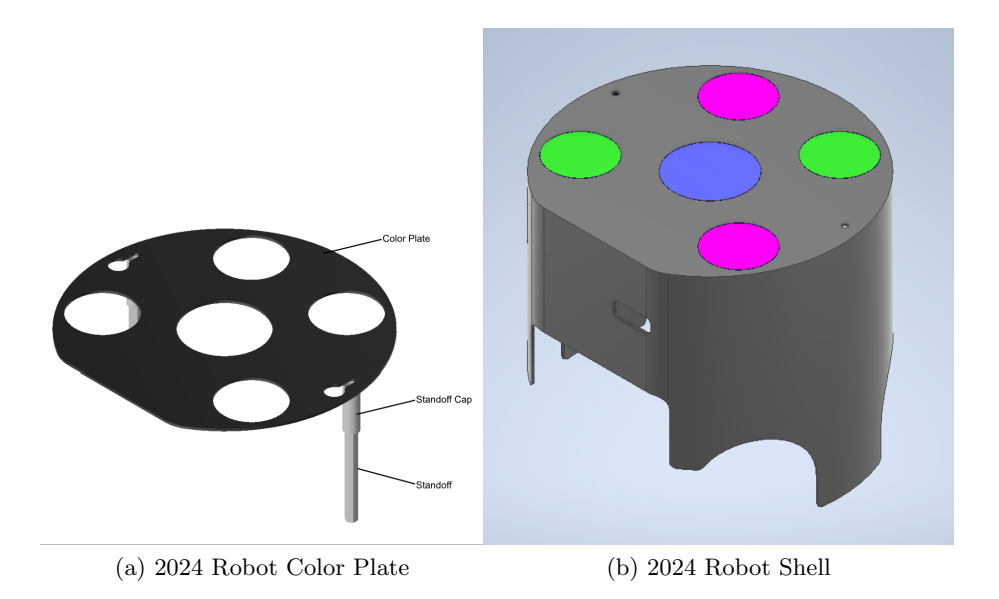
Our main mechanical improvement this year was redesigning our shell and color plates. At competition last year, we struggled with our shells as putting them on and off the robots would interfere with wires and sometimes even snap them. Moreover, whenever we needed to access our electrical boards or view the status of our Teensy micro controller, we would need to remove the shell which was far from ideal. Lastly, our color plates were poorly fixed to the shells resulting in a difficult process when we needed to switch team colors. These were similar problems to the ones we faced in Bordeaux during RoboCup 2023 and we attempted to solve these issues with a magnet based solution discussed in our TDP from last year and shown in Figure 1. While this solution seemed elegant at the time, we failed to realize that the presence of magnets near our radio resulted in communication problems.
As such, we decided to once again redesign our shells for our robots.
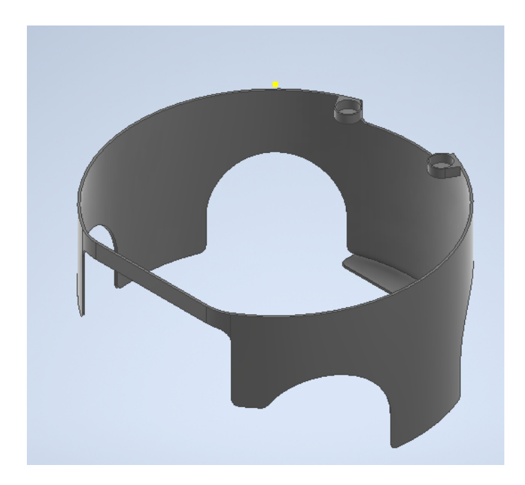
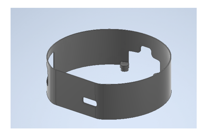
In our new shell design, we were able to create a shell that is screwed to the bottom half of the robot as shown in Figure 2. This was done as the changes that have to be made in a competition are more frequently occurring in the top half of our robot where the electrical boards are. By fixing the bottom half of the shell to the robot, we do not have to worry about detaching and reattaching the bottom part of the shell which usually catches on our break beam wires, causing them to snap. The top half of our shell, depicted in Figure 3, slides into the holes that are present in the bottom half. This allows for secure attachment of the shell while also allowing for easy removal. The top half of the upper shell also has an open top, allowing us to easily debug our Teensy microcontroller. Previously our shell had a closed top, requiring the entire shell to be removed to view the microcontroller. The color plate is attached to the top of the shell via a hinge, enabling us to change our team color from blue to yellow when needed with much more ease than in previous years.
2025 Robot Specification
| Dimension | ∅180mm x 146mm |
|---|---|
| Total Weight | 2.59 kg |
| Drive Motors | Maxon EC 45 Flat (651610) |
| Encoders | Maxon Encoder (673029) |
| Wheel Diameter | ∅53mm |
| Dribbler Motor | Maxon EC 16 (405812) |
| Dribbler Bar Diameter | 15 mm |
| Dribbler Damping Material | Poron Microcellular Urethane |
| Kicker Charge | 4000µF @ 250V |
| Kick Speed | 6m/s (max speed) |
| Chip Distance | approx. 3m |
Electrical
This year's electrical changes were primarily focused on the design of Motorboard v1.0 and Control Board v4.0 with the objective of improving our existing motor driving system. The following table summarizes the changes on the electrical stack:
Electrical stack changes from 2024 to 2025
| Part | 2024 | 2025 |
|---|---|---|
| Radio | nRF24L01 | nRF24L01 |
| Base Station | RaspPi 4 + nRF24 | RaspPi 4 + nRF24 |
| MCU | Teensy 4.1 | Teensy 4.1 |
| Control Board | v3.4 | v4.0 |
| Motorboard | N/A | v1.0 |
| Kicker Board | v3.3 | v3.3 |
| Battery | 18.5V 90C 1600 mAh | 18.5V 90C 1600 mAh |
Background
During the 2024 competition in Eindhoven, Netherlands our team was facing one of the worst hardware constraints until date. Our motor driving system was experiencing an unprecedented delay, resulting in undrivable robots. After multiple attempts through firmware modifications and hot-fixes we concluded that the underlying hardware implementation was at fault. Our previous system relied on a Xilinx Spartan 3 FPGA for the control logic. Even after modifying the existing RTL by simplifying the control logic we weren't able to resolve the delay problem. The proposed solution was to implement an entirely new motor driving system based on STM's STSPINF0A IC as our controller of choice. This new motor driving system was inspired by the corresponding STM development board as well as the A-Team's motor driving system described in their 2023 TDP.
In addition, the team has decided to move towards a more modularized electrical stack, where each system lies in an independent board. This approach aims to improve debugging capabilities and also makes generational changes less costly and independent of other parts of the electrical system. The motivation behind this change arises from the design of last year's Control v3.4, where we only needed to replace the microcontroller and radio connectors, but as a result of a monolithic control board, we ended also including our old motor driving system and power regulation system, which drastically increased the cost of what should have been a minor hardware change.
Motorboard v1.0
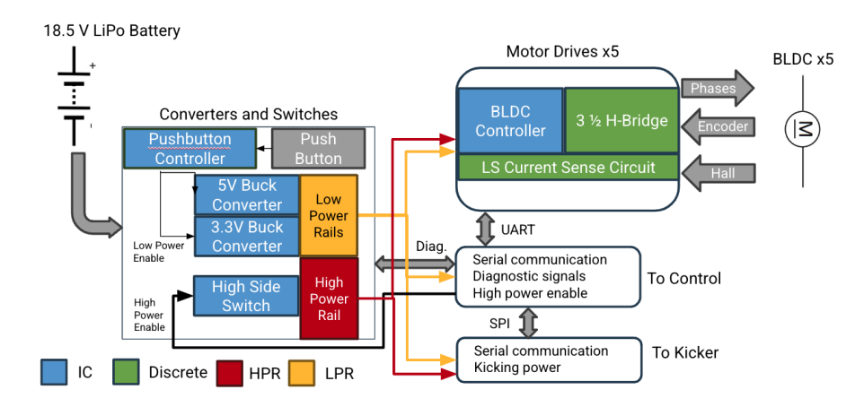
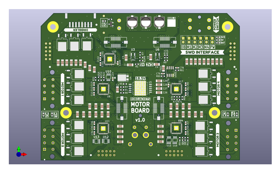
Motorboard is the newest integration to our electrical stack. Although it is a new board, most of it's functionality could be found in our previous control board. Motorboard's functionality revolves around power regulation and motor driving. In the board we can find our DC-DC converters, high and low power rails, power distribution connectors, and our motor driving system. The following diagram contains an overview of motorboard's functionality.
Voltage Regulation & Power Distribution Our robot operates using three different voltage levels (18.5V, 5V, 3.3V) which we have categorized into a High Power Rail (18.5V) and Low Power Rails (5V and 3.3V). The HPR is protected using a fuse and a protection IC (VN5E006ASPTR-E). This protected power rail is then fed directly into the motor driver system to power the motors and it is also passed through an XT-30 connector into the kicker board to power our kicker system. It is also fed into the 5V and 3.3V monolithic regulators (MPM3620GQV-P) which drive the LPRs. These LPRs are then used to power most logic components in this board and other boards including the MCU, radio, OLED display, and other discrete components such as LEDs.
Motor Driving System Following from the background section, our team designed a new motor driver system revolving around the STSPINF0A (SPIN for short). Being STM's integrated solution, the SPIN chip is equipped with an integrated driver capable of driving 6 N-Channel MOSTFETs under two different configurations: 6 step and FOC. The SPIN also provides three highspeed timers which are used for both configurations. In our case we are using the 6 step algorithm, therefore, the motor's Hall Sensors are connected to the SPIN's high-speed timer to allow for real-time motor phase/position detection. This information is directly used to transition between the 6 different states. The implementation of the 6 step algorithm is still a work in progress which can be found on our firmware GitHub repository. Our Maxon motors are also equipped with encoders which are driven directly with an RS-422 differential pair transmitter. We have included the appropriate receiver (SN75157) on Motor Board which delivers a clean encoder signal into the SPIN. The following figure shows a top view of Motorboard's finalized design. Each motor block has been labeled appropriately.
Control Board v4.0
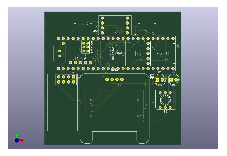
As explained in the background section, Control Board v3.5 has been divided into Motorboard v1.0 and Control Board v4.0. Therefore, Control Board no longer hosts the motor driving system and the voltage regulation system, instead those has been moved to Motorboard, leaving Control Board v4.0 with our Radio connector, MCU connector, IMU connector, and a new OLED display for improved debugging and real-time status updates. In other words, Control Board has been simplified into an interface board intended to connect together all the remaining systems in the robot. The following figure shows a top view of our finalized Control Board v4.0:
Firmware
This section describes the firmware improvements and optimizations implemented in the 2025 season.
Robot Testing
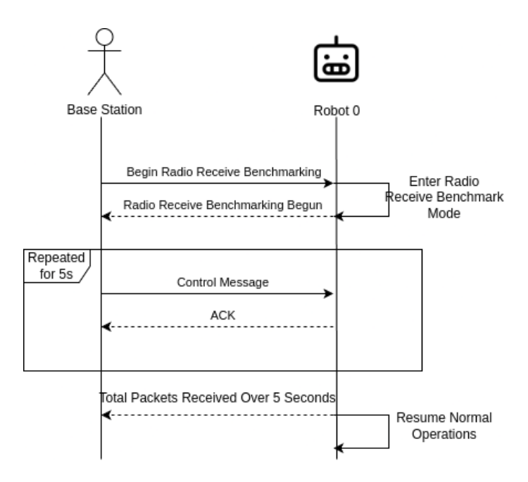
At the 2024 RoboCup competition, time constraints led the team to connect the new microcontroller (a Teensy 4.1) to the existing robot control board via a system of wires and breadboards. Although the setup was functional, peripheral connections between the Teensy and control board often became disconnected leaving the team to manually debug electrical connections. At competition, the team wrote a series of tests to diagnose what peripheral was disconnected to speed up the electrical connection testing. Each test, however, needed to be manually programmed onto the Teensy causing the testing procedure to be lengthy and placing unneeded strain on the Teensy's flash storage. In an attempt to reconcile these limitations, the updated Teensy firmware has a series of testing modes for "unit testing" the various connections and peripherals of the Teensy. In general, each testing mode can be enabled via a flag sent from the base computer dictating a specific testing mode. After receiving the test flag, the robot completes a set of pre-defined tasks returning an update status before finally returning a full task status and switching back to normal operations.
In figure 7, robot 0 receives a control message from the base station indicating it should benchmark it's onboard radio. Robot 0 then switches to radio benchmarking mode where it listens to packets for 5 seconds before reporting the total number of received packets to the base station. Finally, Robot 0 switches back to normal operations.
Motion Update Delta
In the context of firmware, our team has defined our motion update latency as the time it takes our motion control loop to take measures from the IMU and encoders, calculate an updated command, relay the command to the motion control system, and relay kicker commands to the kicker. Ideally, by minimizing this motion update latency the robot should be able to more smoothly perform minor corrections to its current velocity.
For scheduling firmware tasks, the team has opted to utilize the RTIC (Real-Time Interrupt-driven Concurrency framework) RTOS. In RTIC, tasks can be scheduled as software and hardware tasks. Software tasks must be dispatched by an executing task and hardware tasks are dispatched by some interrupt (i.e. a GPIO trigger or a timer elapsing). Previously, the motion update loop was scheduled using a loop where a motion update loop spawned a delay software task using the Teensy's systick timer as a monotonic timer. Using the systick timer to effectively schedule the motion update loop was successful at achieving motion update deltas of roughly 2ms. To decrease this delta between subsequent motion update loops, a periodic interrupt timer on the Teensy was devoted to scheduling the motion update loop. This allows the motion update loop to be scheduled via a high priority hardware task. By switching to using the periodic interrupt timer to schedule the motion update loop, the team was able to decrease the motion update delta to, on average, 0.5ms reliably.
Software
This section describes the software improvements and enhancements implemented for the 2025 season.
Rules Compliance
We made significant improvements to our rules compliance logic heading into the Eindhoven competition, including handling game states such as kickoff and free kick. However, there were still lingering issues that resulted in penalties on the field.
First, our robots did not respect an opponent's ball placement. To fix this, we added the so-called "stadium shape" to our geometry package. The shape is added as an obstacle to surround the ball and kicking robot during ball placement. When added as an obstacle, the robots avoid this space, adhering to the rules. The stadium shape is a set of our existing circle and rectangle shapes. The existing rectangle shape could not be represented at an angle, so this was an additional improvement.
Second, our planner that escapes obstacles did not avoid hitting the ball. At competition, this typically manifested itself during the STOP state, when robots would hit the ball when trying to exit the ball's obstacle zone. Rather than creating a "simple" path, which could not handle internal obstacles (i.e., the ball), we now use our standard path generation planner, adding the ball as an obstacle.
Ball Collection
One of the most fundamental tasks for our robots is to retrieve the ball, such as to allow the offense to obtain possession and pass. In Eindhoven, this was entirely done with our traditional path planners, which was completed based on conditions from vision (i.e., vision's "idea" of the robot's position being close to the target). Although this worked a majority of the time in Eindhoven, where the vision was very well calibrated, there were still instances of our robots not actually having possession when software believes that it does. At our home field, where our vision system is less robust, the issue is significantly worse. We altered our revamped collect planner to take into account "ball sense", which firmware sends when the break beam detects the ball inside the robot's dribbler. Now, our strategy is more consistent.
Kick Planning
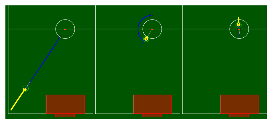
At the Eindhoven competition, our kicking was handled by the pivot kick planner. This planner worked using two key states, approach, pivot, and kick. During approach, the robot towards the ball. Then it would pivot, driving in an arc around the ball at a radius of 0.5m, ultimately facing the target. This has two issues. First, driving in the arc is very slow, allowing opposing robots to simply steal the ball. Second, if the ball was closer to the wall than the radius of the arc, there approaching the ball was impossible. During the kick state, the robot drives straight forward, activating the break beam and kicking the ball. This presents its own issue: Any discrepancy in the angle of robot or the "straight" path would ruin the aim of the shot.
To improve our kicks, we designed a new rotate path planner. This allows our robots to rotate in-place. This is in contrast to before, when we would rotate around a specific point outside of the robot. Therefore, the task of kicking can be broken into 3 planners. Our collect planner (existing) gathers the ball, rotate path (new) turns toward the target, and line kick (existing) drives through to perform the kick. This solves the issues we observed. We can now collect the ball quickly rather than slowly rotating around it, and kick more accurately because we maintain possession as we pivot.
Path Planning
In Eindhoven, the trajectories for robot paths were generated via RRT. We were concerned that RRT was unnecessarily complex given the relatively few amount of obstacles on the field, and was therefore contributing to possible latency in our stack. In addition, RRT would in rare cases generate convoluted paths.
We created a new path trajectory generator, which was heavily inspired by TIGERs Mannheim's 2019 and 2024 TDPs. To generate a path, we start with the simple straight-line path from robot to destination. If there are no obstacles, we stop here. If there are, we generate n points within a radius range of r₁ and r₂ of the robot and angle d₁ and d₂ off the straight-line path. We sort the points by angle off the straight line path, and incrementally step with size s off of the robot, checking at each candidate point if there was a direct unobstructed path to the target. Because we start with the closest angle and closest distance to the robot, we can terminate once any valid path is found, as this is the optimal path given the randomly generated points. If no valid path is found, we defer to RRT to generate a more complex path to route around the obstacles.
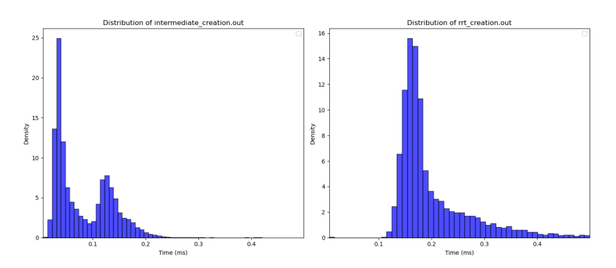
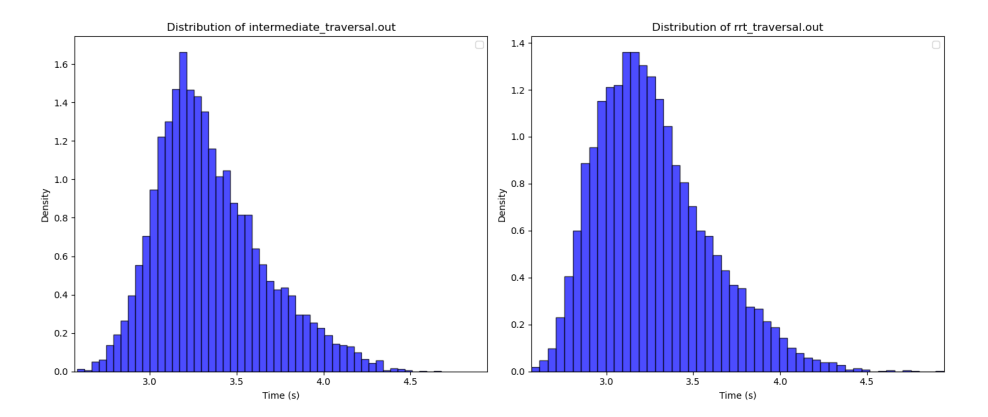
To test the performance differences between the random intermediate points (RIP) and RRT, we selected random robot, obstacle, and target locations. We then compared the time to generate a path and the length of the path (in expected time to travel on it). We found that RIP's mean creation time was 0.12ms lower than RRT, while the paths from RIP take 8ms longer to traverse as compared to RRT. While this poses a substantial tradeoff, RIP is shown to be advantageous when the mean creation time needs to be minimized to lessen the load on the software stack. The data from when RIP cannot find a path and defaults to RRT is visible in the creation time graph, and aligns with the metrics from RRT.
Position Testing
Our robot's positions are assigned by the robot factory position. Testing a particular position on a robot typically required a code change (e.g., manually checking the robot's id and setting its position to the one of interest). This can lead to bugs in testing, inefficiency, and a lot of re-written code when we need to test at different points in time. We created a position overriding system to allow for easier testing of our robots. Each position is added to our UI, and when clicked, sends a message with the requested position's robot factory position via the new override position ROS topics, of which there is one per robot. The position is then updated, and will override any automatic updates by the robot factory position until the override position is reset. This makes testing new and different positions extremely efficient.
Docker and Ubuntu Upgrade
We created a Docker container to streamline our development process by providing a reliable, efficient, and standardized environment for our software stack. Built on Ubuntu 22.04, it supports both arm64 and amd64 architectures, ensuring accessibility across devices. The container features a noVNC-based virtual desktop for running and interacting with the soccer simulator. It includes all necessary dependencies, such as ROS 2 Humble, Git, and our team's repository, enabling new developers to start immediately. Port forwarding is configured for VS Code Remote Development, allowing seamless coding, and the container also supports communication with the external referee. By replacing our previous reliance on unreliable and time-consuming virtual machines, the Docker container simplifies onboarding, eliminates compatibility issues, and provides a stable, cross-platform environment that boosts productivity.
We upgraded our codebase to use ROS 2 Humble and Ubuntu 22.04 as ROS 2 Foxy has been officially deprecated. There were some minor changes that had to be made for our project to compile against the new library. One improvement that still needs to be made is our "source script"; in its current state, the ros2 command-line tools cannot find custom message type definitions. The easiest way to fix this is likely to end the practice of manually generating the script and allow the colcon build tool to generate it automatically. This work has begun.
Open Source
RoboJackets continues to open source all aspects of development. Links to software, electrical, and mechanical materials can be found on the RoboCup SSL website, or by searching for "RoboCup" on our GitHub page.
References
- Nayak et al. RoboJackets 2024 Team Description Paper. 2024.
- Avidano et al. The A-Team Technical Description Paper 2023. 2023.
- STM Development Board. url: https://www.st.com/en/evaluation-tools/steval-spin3202.html
- VN5E006ASPTR-E Datasheet. url: https://www.st.com/resource/en/datasheet/vn5e006asp-e.pdf
- MPM3620 Datasheet. url: https://www.digikey.com/en/htmldatasheets/production/1785101/0/0/1/mpm3620-datasheet
- RoboJackets Firmware Repository. url: https://github.com/RoboJackets/robocup-rustware
- Teensy 4.1 Specifications. url: https://www.pjrc.com/store/teensy41.html
- Real-Time Interrupt-driven Concurrency (RTIC) framework. url: https://rtic.rs/2/book/en/
- Rules of the RoboCup Small Size League. url: https://robocup-ssl.github.io/ssl-rules/sslrules.html
- Mark Geiger Nicolai Ommer Andre Ryll. TIGERs Mannheim - Extended Team Description for RoboCup 2019. 2019.
- Michael Ratzel Nicolai Ommer Andre Ryll and Mark Geiger. TIGERs Mannheim - Extended Team Description for RoboCup 2024. 2024.
- Open Source Contributions. url: https://ssl.robocup.org/open-source-contributions/