RoboTeam Twente Extended Team Description Paper for RoboCup 2025
Adham Elhabashy, Amirreza Akrami, Crina Gurev, Deef van der Linde, Dylan Bruggeman, Farida Elsadany, Flim de Jong, Hamza Elkady, Jonathan Jeuring, Lu Na Izquierdo Collantes, Marijn Buitenweg, Raswanth Vetrivel, Reyhan Iri, Yuying Ba
University of Twente (UT), Enschede, the Netherlands; Saxion University of Applied Sciences, Enschede, the Netherlands; RoboTeam Twente, Capitool 25 Enschede, the Netherlands
Abstract RoboTeam Twente continues its participation in the Small Size League of RoboCup, pushing the boundaries of robot performance and control. This year, advancements include the integration of feedforward control, incorporating static friction effects, along with an improved friction estimation method that accounts for directional dependencies. Trajectory planning has been enhanced through the use of Bang-Bang trajectories with jerk-limited acceleration, leveraging the Ruckig library for smoother motion control. These developments aim to increase the precision, adaptability, and efficiency of the robotic system developed by RoboTeam Twente.
Further improvements include the adoption of larger motors and a complete overhaul of control code generation using MATLAB and Simulink for automated deployment. These innovations collectively contribute to a more robust and intelligent robotic soccer system, advancing RoboTeam Twente's competitive edge in RoboCup 2025.
Keywords: RoboCup · Feedforward Control · Friction Estimation · Simulink Code-Gen · Bang-Bang Trajectories · Motor Performance Evaluation
Introduction
RoboCup is an international robotics competition that fosters advancements in artificial intelligence and autonomous robotics, with the ultimate goal of developing a fully autonomous team capable of beating human soccer players by 2050. RoboTeam Twente competes in the Small Size League (SSL), which emphasizes high-speed, precise motion control, strategic team coordination, and intelligent decision-making.
Over the past year, RoboTeam Twente has focused on improving control and motion planning. By introducing feedforward control mechanisms that account for static friction and other dynamic factors, the robots can achieve more precise velocity tracking. Additionally, refining trajectory planning through jerk-limited Bang-Bang motion reduces wheel slippage and enhances motion stability.
This paper details the technical advancements and innovations implemented in RoboTeam Twente's 2025 robot design. Improvements in motion control through friction estimation and feedforward compensation, the benefits of integrating Simulink-generated control code, and the effects of jerk-limited trajectory planning are all discussed. Additionally, a transition to more powerful motors is highlighted. These developments collectively aim to enhance the performance, reliability, and competitiveness of RoboTeam Twente in the upcoming RoboCup competition.
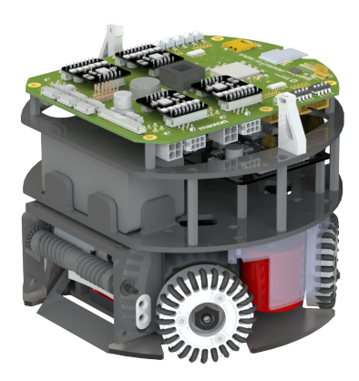
Robot Specifications
| Robot Version | v2024 | v2025 |
|---|---|---|
| Dimension | 179 x149mm | 179 x149mm |
| Driving motor | ECXFL32L 48V 50 Watt | TBD |
| Dribbling motor | Maxon DCX19S EB SL 24V | Maxon DCX19S EB SL 24V |
| Wheel diameter | 56 mm | 66 mm |
| Wheel gear ratio | 1:1 | 1:1 |
| Encoder driving motors | MILE 2048IMP | TBD |
| Dribbling bar diameter | 14 mm | 14 mm |
| Dribbling bar length | 70 mm | 70 mm |
| Encoder dribbler bar | ENX10 EASY 1024IMP | ENX10 EASY 1024IMP |
| Dribbler gear ratio | 5:3 | 5:3 |
| Microcontroller | STM32F767ZI | STM32F767ZI |
| Ball sensor | Custom Infrared sensor | Custom Infrared sensor |
| Motor driver | TI DRV8323SRTAR | TI DRV8323SRTAR |
| Inertial Measurement Unit | Xsens MTi-3-8a7g6t | Xsens MTi-3-8a7g6t |
| Battery | 6S1P 22.2V 150C LiPo | 6S1P 22.2V 150C LiPo |
| Kicker-and-chipper-board Capacitor | 1000 µF; Working voltage 200V | 1000 µF; Working voltage 200V |
| Wireless Communication | SX1280 2.4GHz | SX1280 2.4GHz |
Friction Estimation and Feedforward Control
Static Friction Estimation
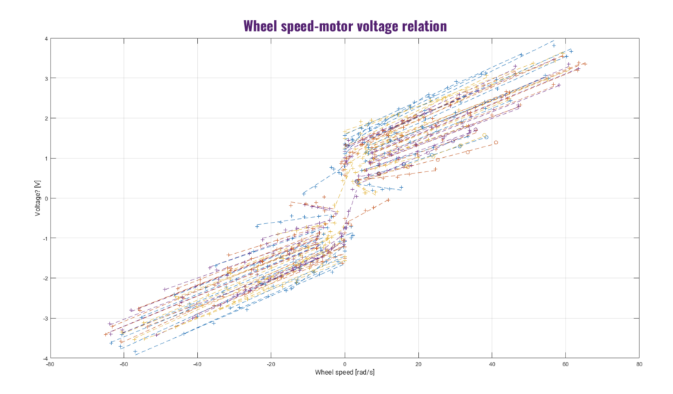
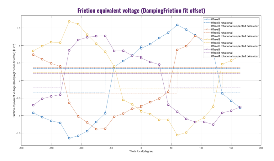
To accurately model and compensate for static friction in the robot's movement, a steady-state test was conducted. This test was designed to measure the relationship between the applied motor voltage and the resulting body velocity while ensuring that the robot maintained a constant reference velocity.
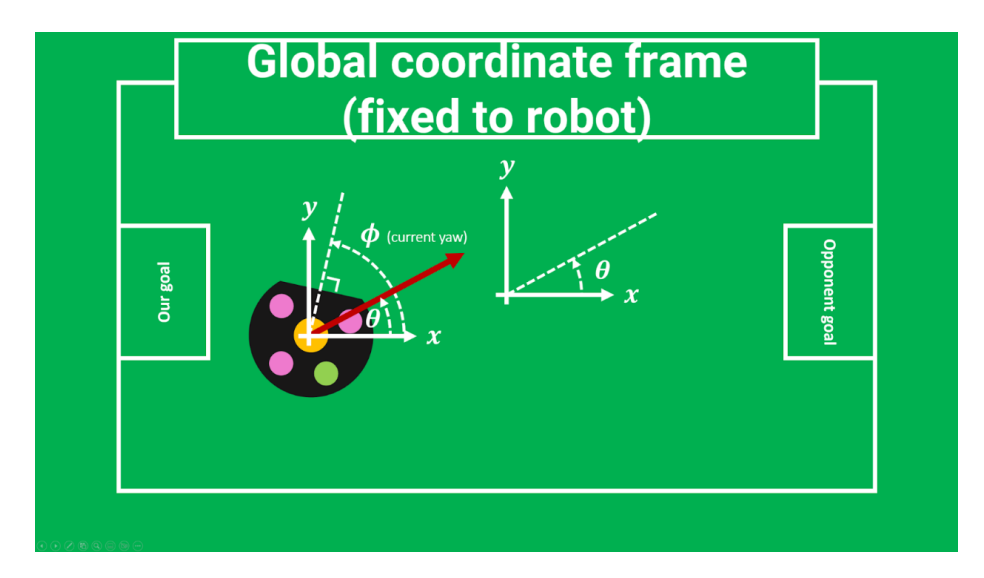
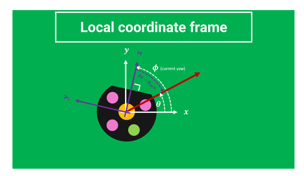
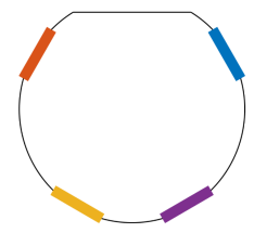
Steady-State Test The steady-state test involved commanding the robot to move at various velocities and directions while maintaining a fixed yaw angle. The reference velocity, represented by its magnitude ρ and direction θ, was sent to the robot in a global coordinate frame. The actual movement is measured in the robot's local coordinate frame. Understanding the transformation between these frames is crucial for analyzing the test results accurately. The global coordinate frame, shown in Figure 2, is fixed to the center of the field:
- The x-axis points towards the right goal.
- The y-axis is perpendicular to the x-axis, forming a right-handed coordinate system.
- A positive angle is defined in a counterclockwise direction.
This frame is used to define the robot's commanded velocity (ρ, θ) before being transformed into its local frame.
Feedforward Control
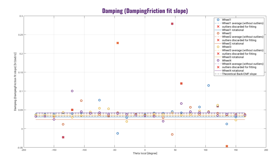
To compensate for the estimated friction and damping experienced by the wheels, a feedforward control strategy was implemented. By incorporating both static friction and damping feedforward terms, the final feedforward voltage command for each wheel is given by:
$$V_{\rm ff} = V_{\rm damping} + V_{\rm friction}$$ $$= d \cdot \omega_{\rm ref} + f(\theta)$$
where d is an experimentally determined damping coefficient, ωref is the reference angular velocity of the wheel, and f(θ) is a fitted function representing the friction offset as a function of the driving angle θ.
This ensures that the robot compensates for resistive forces before relying on feedback control, leading to more accurate velocity tracking.
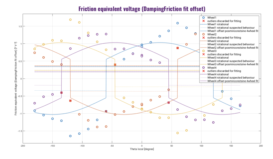
Friction Compensation For the friction compensation, different fitting approaches were considered, including a simple sign-based model and sinusoidal approximations. Ultimately a combination was used resulting in a general formula of:
$$f(\theta) = a \cdot \sin(\theta) + b \cdot \operatorname{sign}(\sin(\theta)),$$
where a and b are determined experimentally. The function f(θ) was determined by fitting the experimental data, as illustrated in Figure 7.
Effectiveness of the Feedforward Control
After implementing the feedforward control, noticeable improvements were observed, particularly in low-speed reference tracking. Static friction compensation significantly enhanced performance. Further testing is required to determine the exact improvements.
Simulink Code-Generation for Control
The control of the propulsion of the robot was thusfar implemented in pure embedded C-code. This results in a moderately efficient (though far from welloptimized), and largely functional, control subsystem. There are, however, a few key areas in which this approach left more to be desired:
- There is no high-level overview of the system unless this overview is actively maintained.
- Refactoring is time-consuming and potentially error-prone
- Control and modelling are difficult to integrate
In previous years it was noticed that this approach led to a relatively slow development iteration cadence, and a similarly slow onboarding process. In an attempt to avoid these problems, a workflow that utilizes Matlab Simulink to generate the control code has been integrated. Preliminary results suggest good controller performance with a reduction in code complexity and iteration time.
Jerk-Limited Bang-Bang Trajectories Using Ruckig
Motivation for Jerk-Limited Acceleration
Traditional acceleration-limited Bang-Bang trajectory planning maximizes efficiency by applying the highest allowable acceleration and deceleration. However, RoboTeam Twente's recent robots experienced significant wheel slippage with this approach, necessitating a refined method. A viable solution was found in jerk-limited motion. Jerk, defined as the rate of change of acceleration, plays a key role in ensuring smooth motion transitions.
- Slippage: Sudden acceleration changes led to significant wheel slip.
- Overshooting and Oscillations: Due to slippage, robots frequently overshot targets and oscillated before stabilizing.
To mitigate these issues, RoboTeam Twente integrated jerk-limited trajectories using the Ruckig library, which ensures smoother transitions between acceleration phases, thereby reducing slippage.
Implementation with Ruckig
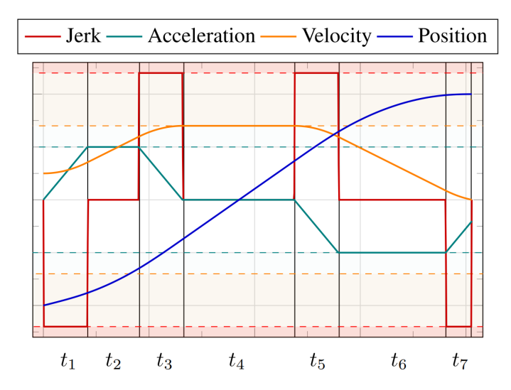
Ruckig provides real-time trajectory generation by incorporating third-order kinematic constraints, specifically limiting jerk j, alongside acceleration a and velocity v constraints. Unlike acceleration-limited Bang-Bang approaches, Ruckig ensures smooth transitions between motion phases, minimizing slippage.
Given an initial state x⁰ and a target state xᶠ, where:
$$\mathbf{x} = \begin{bmatrix} p \ v \ a \end{bmatrix},$$
with p as position, v as velocity, and a as acceleration, Ruckig computes a timeoptimal trajectory satisfying:
$$v_{\min} \le v(t) \le v_{\max},$$
$$a_{\min} \le a(t) \le a_{\max},$$
$$j_{\min} \le j(t) \le j_{\max},$$
for all t ∈ [0, Tᶠ], where Tᶠ is the trajectory duration. If the initial acceleration or velocity exceeds these limits, Ruckig quickly corrects it.
Figure 9 illustrates the relationship between jerk, acceleration, velocity, and position over time.
Effects on Path Planning and Tracking
Incorporating jerk-limited motion into the Bang-Bang trajectory planner improves path tracking and control in the following manners:
- Reduced Slippage: Smooth acceleration transitions reduce wheel slip.
- Better Path Feasibility: Acceleration-limited approaches sometimes generate paths that robots cannot follow due to excessive slip. Jerk-limited control ensures dynamically feasible paths.
This method has not only reduced slippage but also enhanced motion predictability for the robots currently used by RoboTeam Twente.
Testing and Validation
RoboTeam Twente conducted iterative tests on its indoor field. While no objective tests were performed, practical observations indicated:
– Slippage Significantly Reduced: Robots followed paths with improved precision and less slip.
– Lower Wear on Omniwheel Subwheels: Fewer subwheels detached, suggesting reduced mechanical stress, though this remains to be verified if this is directly the result of the jerk limiting.
Since maximum jerk values were tuned through observation, future research is necessary for quantitative validation.
Applicability to Other Teams
This approach is not universally advantageous. RoboTeam Twente's motors could not instantly reach maximum acceleration, making jerk-limiting beneficial. However, teams with more powerful motors may not require it. For teams facing slippage issues, this method presents a viable solution.
General guidelines for evaluating the need for jerk-limiting include:
- Motor Response Time: Faster motors may not benefit significantly from jerk-limiting.
- Friction Conditions: High-friction wheel designs reduce slippage issues.
- Control System Constraints: Controllers with high update rates may compensate for acceleration spikes without explicit jerk constraints.
This limitation motivated developments in Section ?? (??) to integrate motors capable of directly achieving maximum acceleration.
Conclusion
Replacing acceleration-limited Bang-Bang trajectory planning with a jerk-limited approach using Ruckig reduces slippage, leading to smoother and more stable motion. This method serves as a good alternative to the standard accelerationlimited Bang-Bang trajectory planning for any team that experience the same problems with regards to slippage.
Hardware Design and Implementation
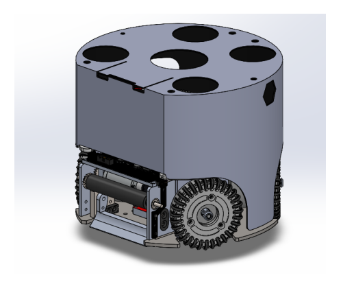
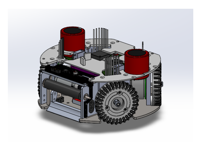
The hardware consists of all the physical components of the robot. This is divided into mechanical and electronic parts. In recent years, RoboTeam Twente has been working on creating a more modular and robust hardware design. This year's team continued on this path by completing the redesigns of the hardware to improve the reliability of the robot. Details of the new design can be found on the wiki of RoboTeam Twente, and the new design is also shown in Figure 10.
Mechanical Design Improvements
The reliability of the hardware has been a recurring challenge over the years. Last year, the mechanics subteam successfully redesigned the entire robot to enhance its reliability. This year, the subteam focused on further improvements, with the most significant changes involving motor verification and the resulting redesign of the bottom assembly for larger motors. It was found out that bigger motors are needed to address the overheating issue experienced by previous year. This will be further explained later on in this report. Additionally, due to less time required for major redesigns compared to last year, the team was able to conduct research as well. These changes are detailed below.
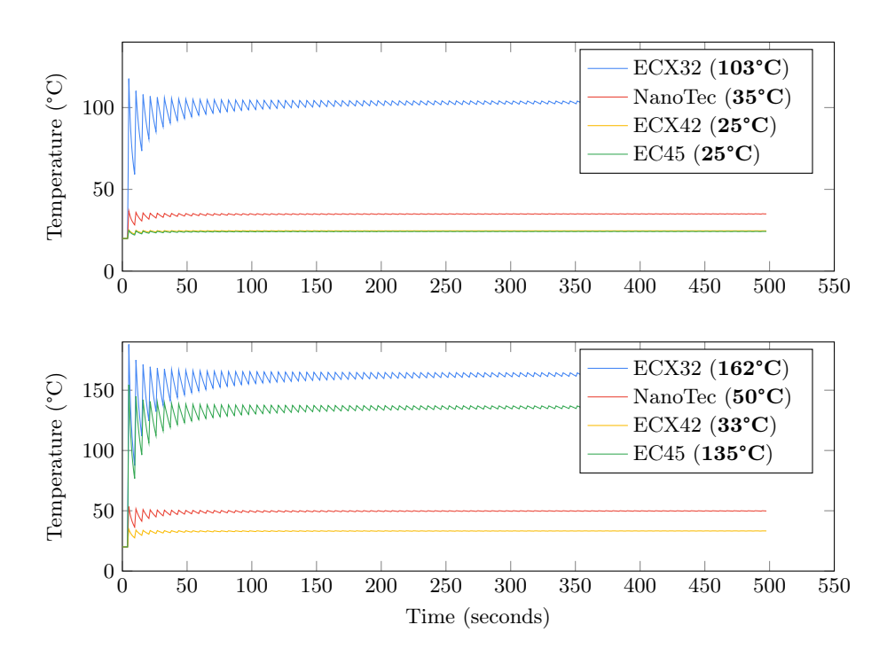
Motor Performance Evaluation Last year, the team transitioned to a directdrive system using the Maxon ECXFL32L motor. However, during RoboCup, these motors failed when playing on a Division A field. At that time, the cause of failure was unclear, and no immediate solution was found. Following discussions with Maxon, temperature calculations were done to verify the operating conditions and determine whether the motors exceeded their specifications.
The analysis begins with the equation for IRMS (Equation 8) and proceeds to compute the stator temperature (Equation 11) and winding temperature (Equation 12):
$$I_{\rm RMS} = I_{\rm ON} \cdot \sqrt{\frac{t_{\rm ON}}{t_{\rm ON} + t_{\rm OFF}}}$$
$$\Delta T_W = \frac{(R_{\text{th1}} + R_{\text{th2}}) \cdot R_{TA} \cdot I_{\text{RMS}}^2}{1 - \alpha_{Cu}(R_{\text{th1}} + R_{\text{th2}}) \cdot R_{TA} \cdot I_{\text{RMS}}^2}$$
$$\Delta T_s = \frac{R_{\text{th2}}}{(R_{\text{th1}} + R_{\text{th2}})} \cdot \Delta T_W$$
$$T_s = T_{\text{ambient}} + \Delta T_s$$
$$T_W = T_{\text{ambient}} + \Delta T_W$$
Using these equations, the temperature evolution of the stator and windings over time was determined to assess compliance with motor specifications. The results, shown in Figure 11, indicate that the winding temperature of the current motors exceeded the specification of 155◦C, reaching 162◦C.
Ongoing Research and Development
Two research projects were initiated:
Front Assembly Damping: Investigating methods to quantify ball-handling improvements in linear motion. Current evaluations of damping systems rely on subjective observations, and this study aims to develop a standardized testing framework.
Kicker Add-on Shape: Initially explored but put on hold due to minor performance improvements and time constraints.
The damping research is entering its testing phase and is expected to yield results by RoboCup 2025.
References
- Nicolai Ommer, A.R., Geiger, M.: Tigers mannheim extended team description for robocup 2019 (2019), https://tigers-mannheim.de
- Berscheid, L., Kröger, T.: Jerk-limited real-time trajectory generation with arbitrary target states. arXiv preprint arXiv:2105.04830 (2021), https://arxiv.org/abs/2105.04830v2
- Monat, C., Dankers, E., Skurule, K., Steenmeijer, L., Sijtsma, S., Diamantopoulos, S., Aggarwal, R., Smit, T., van Harten, A.: Roboteam twente extended team description paper for robocup 2022 (2022), https://ssl.robocup.org/wp-content/uploads/2022/04/2022_ETDP_RoboTeam-Twente.pdf
- van der Kaaden, B., Krommendijk, C., Buzogany, C., Capitani, D., Ayad, G., Ward, G., Kroijenga, J.G., Willigers, J., de Jong, J., González Torres, J.J., Muchembled, J., Hoekstra, L., Winters, L., Petrea, M.R., Mahmoud, M., Srinivasa Kumar, P.K., Roetenberg, R., Tollardo, S.: Roboteam twente extended team description paper for robocup 2024, https://tdpsearch.com/#/tdp/soccer_smallsize__2024__RoboTeam_Twente__0?ref=list