SPbUnited TDP for RoboCup 2025
Alexandr Fradkov, Sergey Filippov, Alexandr Meshcheryakov, Boris Viktorov, Iulia Merzlyakova, Ilia Ustinov, Vasilii Ivanov, Mikhail Lipkovich, Yurii Glazov, Arsenii Iarmolinski, Saveliy Malyshev, Semyon Medvedev
Department of Theoretical Cybernetics, St. Petersburg State University, Russia; Presidential Lyceum of Physics and Mathematics 239, Russia; Institute for Problems of Mechanical Engineering (IPME), Russia
https://english.spbu.ru/ · http://www.239.ru/ · https://ipme.ru/
Abstract This paper presents the SPbUnited Team Description Paper (TDP) for RoboCup 2025, detailing significant advancements since our previous participation under the name URoboRus. We highlight significant hardware improvements, transition from MATLAB to Python, which streamlined development workflows and improved system integration. The team's architecture follows the strategy-bridge concept, enabling robust multi-threaded processes for data acquisition, decisionmaking, and robot control. Key innovations include an enhanced role assignment mechanism based on priority-driven selection metrics, a modular action composition framework for dynamic robot behavior, and an optimized pass-finding algorithm utilizing the Nelder-Mead method for efficient point evaluation. These developments collectively enhance our team's strategic flexibility and on-field performance, ensuring adaptability to diverse match scenarios.
1 Introduction
SPbUnited is a team participating in the RoboCup Small Size League. We previously compete under the name URoboRus, but due participants changes we decided to rename our team to SPbUnited in 2023. Although we haven't participated in the world stage of RoboCup competition yet (only in online one), we attended the RoboCup Brazil Open three times and achieved second place in 2024. This paper presents our recent developments in hardware and software. It focuses on improved robot behavior, optimized passing strategies, and system architecture enhancements.
2 Hardware
Our team still uses the same hardware described in the previous TDP [1], though several significant modifications have been made mainly to improve ball handling capabilities. The rest of changes were aimed at improving stability of the robots. Overall specifications of our current robots are given in a table 1.
Table 1. Robot parameters
| Design version | 2024 |
|---|---|
| Robot dimensions | 179.5 x 148 mm |
| Robot weight (with battery) | 3.8 kg |
| Drive motors | Maxon EC 45 flat, 50 W, 400106 |
| Drive gear ratio | 18:60 |
| Wheel dimensions | 57 mm |
| Dribbler motor | Maxon EC-max 22, 25 W, 283856 |
| Dribbler gear ratio | 50:30 |
| Dribbler roller dimensions | 17 X 78 mm |
| Kicker | chip, straight kick |
| Kicker energy | 59 J (250 V, 1880 µF) |
| Battery | 7S, 3 Ah, with BMS, avg. 25.9 V |
| Motor drivers | Custom BLDC driver |
| Microcontroller | STM32F429 |
| Radio | Control - NRF24L01, telemetry - ATSAMR30M18 |
| Sensors | Encoders, Hall sensors, IMU, ball presence sensor |
2.1 Dribbler
During previous competitions our robot's dribbling capabilities were poor and inconsistent. 2022 design of the dribbler was highly dependent on a number of fine adjustments since it worked as unstable 2-touch-point model described in ZJUNlict's 2019 TDP [6]. Without correct tuning for specific ball and carpet surface dribbler would not hold ball properly oscillating between locked and ejected ball states. Also material used for dribbler rollers had very low wear resistance, producing a lot of rubber shavings during it's operation. For the new version of dribbler we set following requirements:
- Fit inside existing robots
- Eliminate need for the accurate tuning
- Improved wear resistance
- Automatic ball-centering, since ball kicked from the side of the dribbler has unpredictable trajectory
- Improved pass catching
We performed a lot of tests varying both dribbler geometry and roller material trying to achieve periodical dynamic steady state between 2-touch-point and 3-touch-point models described in [6], as 3-touch-point model seems more stable and controllable. But considering tightly packed elements of robot around the dribbler we could not get 3-touch-point model to work, so we stayed with the 2-touch-point model.
First of all, to prevent ball from locking between the roller and the ground we switched material of the roller to the harder one with a smaller coefficient of friction. Than we were able to minimize ball vibrations absorbing them with dribbler by giving it more small-range freedom of movement (we increased play in the dribbler axle to several millimeters).
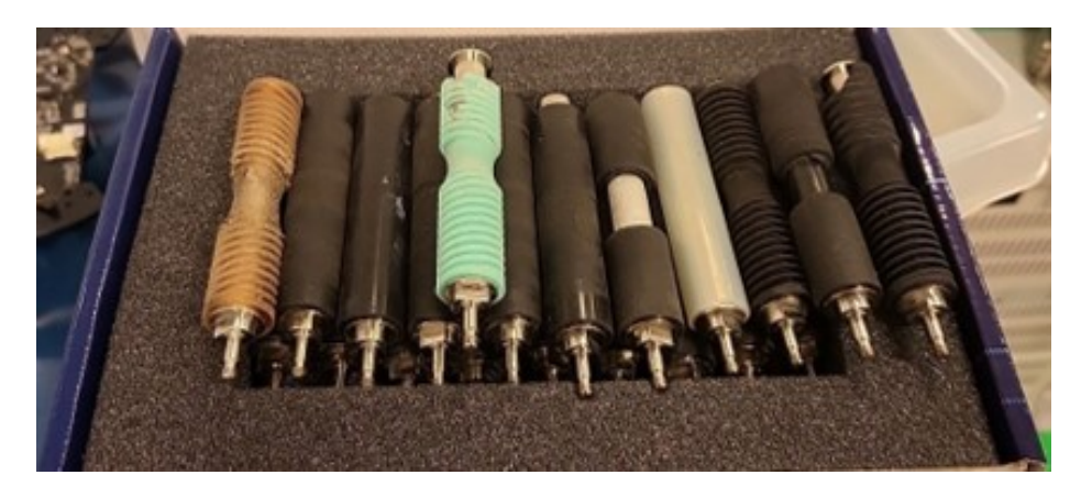
Furthermore we designed roller with highly flexible spiral ridges. Such flexible ridges combine advantages of extremely soft roller material (see fig. 1) (absorption of small ball vibrations that could not be absorbed by the dribbler itself due to it's high inertia) with advantages of harder materials (higher wear resistance).
By giving flexible ridges spiral form we were able to use them as automatic ball-centering mechanism. Also in our test flexible ridges were able to produce significantly more lateral force to the ball compared to the hard groves typically seen in roller designs. Apart of spiral ridges new roller has central grove to provide as much holding force to the centered ball as possible.
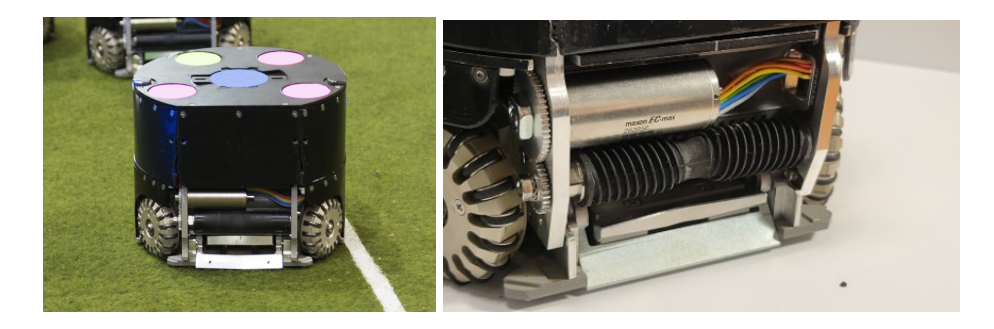
Final design (see fig. 2) of our dribbler has enough holding and centering force to allow lateral and turning movements with the ball at lower speeds even with open loop motor speed controller.
2.2 Ball damper
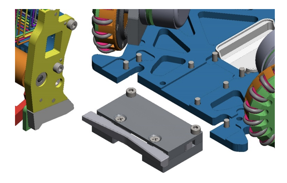
To improve pass catching we designed additional ball damper (see fig. 3) that was thought to absorb kinetic energy of the ball. But during tests we found out that majority of kinetic energy is absorbed by dribbler's damper and not this device, making it almost useless. Though overall pass catching have been improved a lot.
2.3 Kicker
Also in our 2024 robots design kicker schematics and mechanics have been improved a lot. First of all kicker charger voltage have been risen from 150 volts to 250 volts to make faster kicks. This change resulted in a lot of stress on a number of kicker parts. So we had to redesign them accounting to the higher stresses. For example new chip kicker's shovel is made from the steel instead of aluminum.
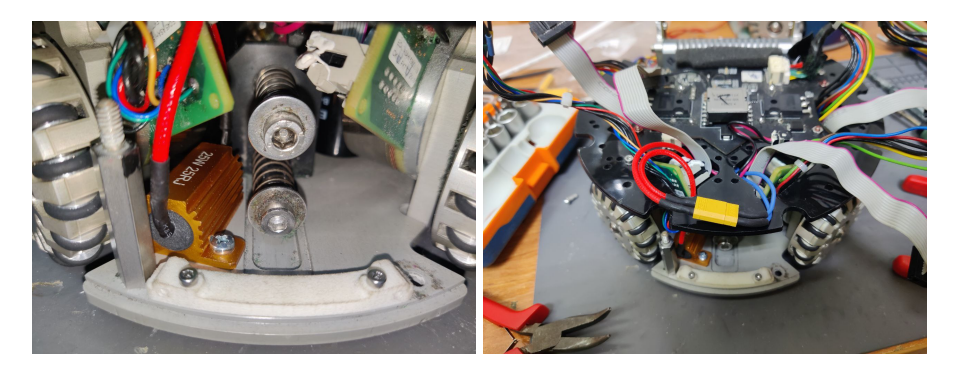
Also during development of passes between our robots we experienced the need to quickly discharge capacitors to adjust kick strength. Discharge resistors originally placed at the kicker PCB were miscalculated in terms of dissipated power and have failed during first discharges, but this was not a problem until active development of passes have began. So in the current version of robots additional 25 W 25 Ohm resistors are added to fully discharge kicker capacitors within a second.
To improve power dissipation this resistor are bolted directly to massive aluminum bottom plate of robot which acts like a huge radiator. With this setup we are able to constantly perform charge-discharge cycle during a game without overheating anything.
2.4 Battery
Battery packs also have been redesigned due to ware and tear. Previous version of batteries were built on Texas Instruments' bq40z80 AFE and experienced lots of issues with last cell due to chip bug. New version uses BQ7693000DBT which monitors all cells correctly. All necessary safety protections like reverse polarity, cell over/under voltage were also been implemented on upgraded boards.
3 Motion control
Till these year we controlled robot only using velocities, but we had a lot of problems with angle. Mostly it was in two situations: 1) When robot needed high precision to kick, 2) When robot had to dramatically increase his linear velocities, it usually couldn't handle his desired angle. We decided to use a gyroscope as a solution to these problems. To calculate angle, robot integrates angular velocity that was given by gyroscope. Then it used the difference between desired angle and calculated as error for PD regulator. To minimize error of calculation we send the desired angle transition and when robot get it he resets his calculated angle to zero. This approach showed a great results in test and real competition. Another problem is that angle transition value can be bigger than byte, so we decided to convert it instead of using two bytes to minimize size of message. Also, we wanted to have more accuracy when sending small values, because it was needed for precise shooting. To meet our requirements we use this function:
$$f(x) = 10 \left( \exp\left(\frac{|x| \cdot \ln(19)}{127}\right) - 1 \right) \cdot \operatorname{sign}(x) \cdot \frac{\pi}{180}$$
4 Software
To be filled by subsections
4.1 General Code Structure
Since the previous TDP [1], the most significant change is transition from using MatLab for high-level coding to Python, which has facilitated the integration of new team members and opened up a range of modern libraries and tools.
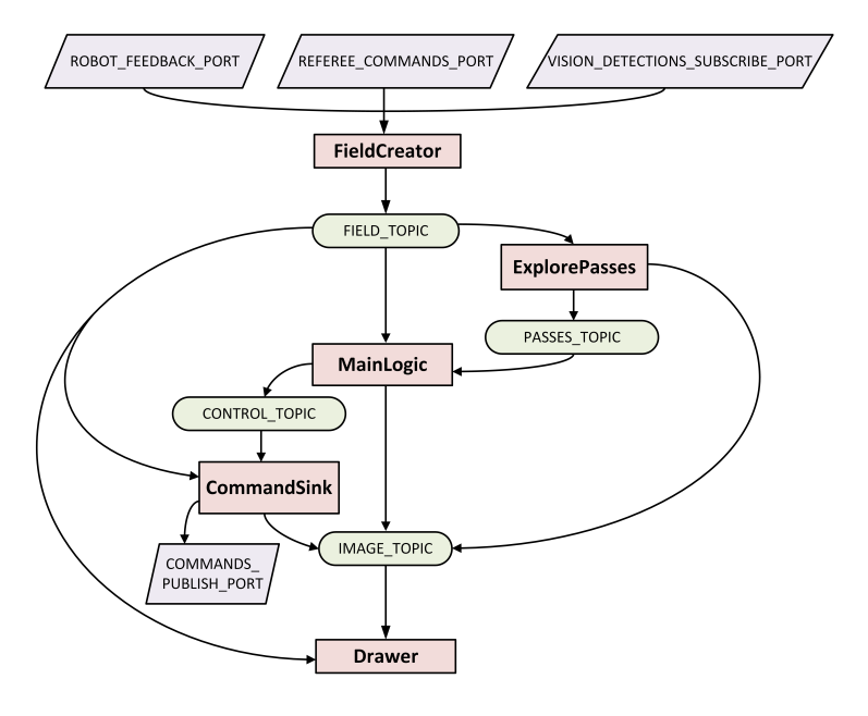
The architecture of our system is based on the strategy-bridge concept [1]. Several key processes run concurrently and communicate as needed. For instance, one dedicated process collects and processes data from SSL-Vision, while another sends commands to the robots. The most innovative aspects of our architecture, however, are the decision-making process and the "pass-finding" process.
4.2 Role Assignment and Behavior Management for Robots
In our system, robots are assigned specific roles such as wall defender, pass defender, pass receiver, etc. Each role is characterized by three key components: role priority, a selection metric to determine the most suitable robot, and role-specific behavior.
Role Priority Roles are assigned based on their priority levels. The selection process is as follows:
- All available robots are evaluated.
- The role with the highest priority selects the most suitable robot according to its specific metric.
- Subsequent roles select from the remaining robots until all roles are filled.
This ensures that critical roles are filled first, maximizing overall team efficiency.
Selection Metric The selection metric evaluates how suitable a robot is for a specific role. In simple cases, it is based on the distance the robot must travel to reach its designated position. For example:
– A wall defender is selected based on the distance between the robot and the wall formation point, with preference given to the closest robot.
Role Behavior Role behavior defines the actions a robot performs once assigned. In most cases, the behavior involves navigating to a designated target point.
– For example, the defensive wall's position remains constant regardless of which robot is assigned.
Single Strategy Iteration Process Each strategy iteration involves the following steps:
- Role Determination: The system identifies the required roles based on the current field situation.
- Metric Calculation: Key points relevant to each role's selection metric are computed (e.g., the ideal position for a defensive wall).
- Robot Assignment: Roles are assigned in order of priority, with the most suitable robot selected for each role.
- Behavior Computation: After assignment, the system computes the behavior for each robot. In some cases, behaviors are interdependent:
- For instance, "pass interceptors" coordinate to evenly distribute coverage of threatening opponents.
4.3 Actions
The assigned role only tells what to do, but it doesn't tell how to do it.
"Actions" are used to control the movement of robots at a high level.
Action is a function that accepts the state of the game (position of the robots and ball on the field, a command from referee, etc.), as well as current instructions for robots (speeds, voltage, etc.). This function also has a scope of definition (for example, obstacle avoidance is an action whose scope of definition is to find an obstacle in its path). The main point is the ability to compose Actions. For example, to kick a ball, no additional behavior needs to be described. There are separately implemented Actions (possibly also being a composition of others). Using them, kicking the ball is literally described as: go to the ball, grab the ball, avoid obstacles, hit the ball. Each subsequent action in the chain can overwrite the commands of the previous one, if it needs to.
4.4 Pass Finding
Finding positions from which to score is essential for creating a dynamic and varied game. To address this, our team initially explored standard methods to avoid overloading our system. Although we considered implementing neural networks, we opted for a more straightforward approach.
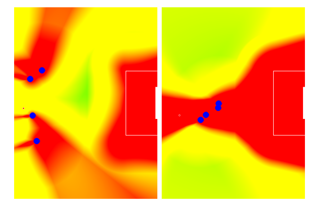
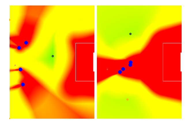
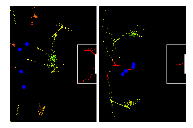
We established criteria to evaluate the "quality" of a point, taking into account factors such as positions of opposing robots, possibility of a subsequent kick, etc.
The challenge is to find a "good enough" solution. A brute-force search over all points could be too time-consuming or result in a coarse step size. An alternative approach is to compute the metric's gradient and search for local minima, but this method can be complex and not universally applicable. Therefore, we use the Nelder-Mead method [3], which starts the local minimum search from both previously identified points and a set of randomly generated points.
While this method does not guarantee a global minimum, it has proven effective in practice by reliably identifying the best point according to our metric, all within an acceptable computation time.
5 Movement with ball
In situations where an opponent is near the ball, our main goal is to take control of the ball as soon as possible. To do this, we aim directly at the ball and attempt to grab it as fast as we can, then we turn around with the ball in our possession.
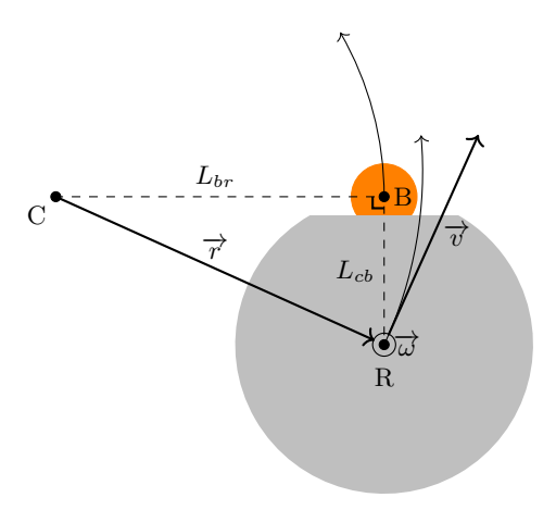
To move the robot with the ball, we calculate necessary angular velocity to maintain smooth turn around the given point at the field. The picture of the robot performing this movement is shown below (Fig. 9):
The formula for calculating the speed of the robot's rotation is:
$$\overrightarrow{v} = \overrightarrow{\omega} \times \overrightarrow{r}$$
The robot's angular velocity matches the speed of its rotation around a given point. This movement allows us to spin the robot at high speed while keeping the ball under our control. However, a sudden change in the angular velocity can cause the robot to lose the ball. Therefore, it's important to turn the robot smoothly when moving with the ball to avoid losing it.
We use the following function to achieve this:
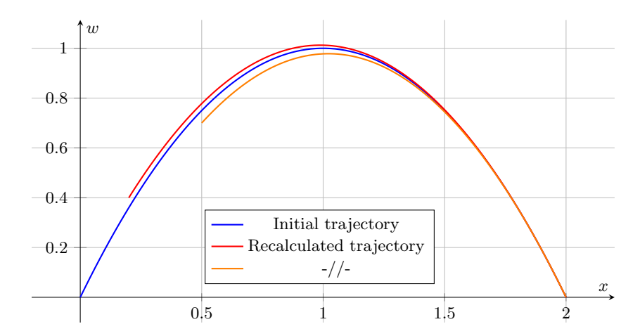
$$\omega = \frac{kx_1 + \omega_0}{x_1^2} x^2 + \left( -k - \frac{2\omega_0}{x_1} \right) x + \omega_0$$
where k is final angular acceleration, x₁ is final angle to which robot is turning, ω₀ is the actual angular speed of the robot, and x is the current position (Fig. 10).
This parabolic trajectory is used to guide the robot to a specific angle with limited angular acceleration.
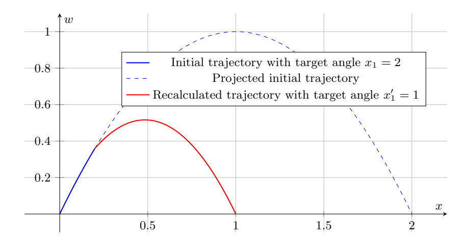
This parabolic trajectory has the advantage that it can be rebuilt at each iteration and will always converge at target angle regardless of accumulated errors from measurments or execution. Additionally, if the desired angle changes during the movement, the robot can adjust it's movement to accommodate the new angle and still maintain possession of the ball (Fig. 11).
6 Conclusion
In this paper, we have presented our main improvements, both in software and hardware. Our primary goals for the near future are to significantly enhance motion control, develop and implement new collision avoidance algorithms, and refine our dribbling.
Acknowledgment
The SPbUnited team gratefully acknowledges the support of PJSC "Gazprom Neft", IPMash RAS, the charitable foundation "Finist", the Research and Manufacturing Association "StarLine", and LLC "KRAVT".
References
- Petr Konovalov, Mikhail Lipkovich, Tseren Frantsuzov, Alexandr Meshcheryakov, Yury Glazov, Boris Viktorov, Andrey Sviridov, Alexander Fradkov, and Voloshina Anastasiia, URoboRus 2022 Team Description Paper.
- J. A. Nelder, R. Mead, A Simplex Method for Function Minimization.
- K. I. M. McKinnon, Convergence of the Nelder–Mead Simplex Method to a Nonstationary Point.
- N. Ommer, A. Ryll, and M. Geiger, TIGERs Mannheim 2019 Extended Team Description Paper.
- A. Wendler and T. Heineken, ER-Force 2020 Extended Team Description Paper.
- Z. Huang, L. Chen, J. Li, Y. Wang, Z. Chen, L. Wen, J. Gu, P. Hu, and R. Xiong. ZJUNlict Extended Team Description Paper for RoboCup 2019