Sysmic Robotics Team Description Paper 2025
Daniela Moya, Claudio Tapia, Gabriel Arcaya, Nicolás Mansilla, Matias Faundes, Gerson Marihuan, Nelson Cortés
Universidad Técnica Federico Santa María Av. España 1680, Valparaíso, Chile
Abstract This paper presents the latest advancements in the fifth generation of Sysmic Robotics' robots, focusing on improvements since RoboCup 2024. The mechanical structure has been redesigned with 3Dprinted PLA components, enhancing durability and flexibility while optimizing component placement. In hardware, the kicker board was refined by eliminating redundant components, integrating a level shifter, and correcting voltage errors. Additionally, a new base station PCB was developed to improve communication reliability. The software transitioned from third-party systems to an in-house architecture, incorporating advanced motion planning and the STP framework for strategic decisionmaking. Finally, the firmware was enhanced with a rigorously defined kinematic model, ensuring better velocity calculations and movement control.
Introduction
Sysmic Robotics is a team of engineering students from the Technical University Federico Santa María. The team first participated in the Small Size League (SSL) during the 2018 RoboCup in Montreal under the name AIS, competing in Division B. In 2023, the team made its second RoboCup appearance in Bordeaux. Since then, the team has worked to upgrade their robots, culminating in their qualification for the 2024 RoboCup in the Netherlands.
For RoboCup 2025, our team has focused on key improvements in four main areas: mechanics, hardware, software, and firmware. These enhancements aim not only to meet RoboCup standards but also to lay the foundation for future developments. The robot's structure was redesigned using 3D-printed PLA components; the kicker board was optimized by removing redundant components and integrating a level shifter while correcting power supply errors; a new PCB for the base station was developed to improve communication reliability; a critical transition from third-party systems to our own architecture was completed, incorporating advanced motion planning and the STP framework for strategic decision-making; and a rigorously defined kinematic model was implemented, enabling more precise velocity calculations and better motion control.
This document details these advances, organized into sections that cover each of the mentioned areas. Our goal is not only to compete in RoboCup 2025 but also to contribute to the robotics community with a scalable, efficient, and welldocumented system that serves as a foundation for future innovations.
1 Mechanics
Since our last submission for the 2024 RoboCup, the robot has undergone several slight structural changes.
1.1 Structure
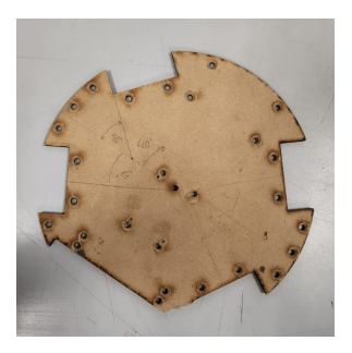
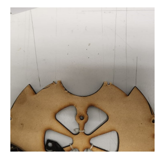
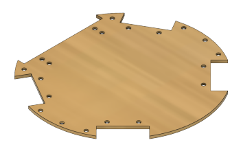
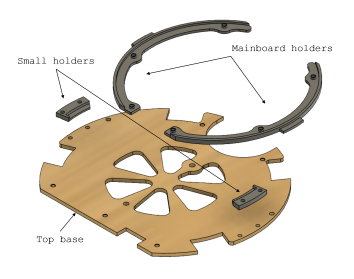
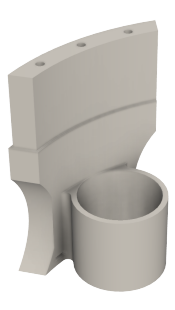
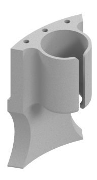
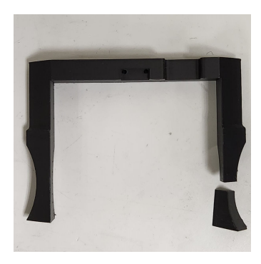
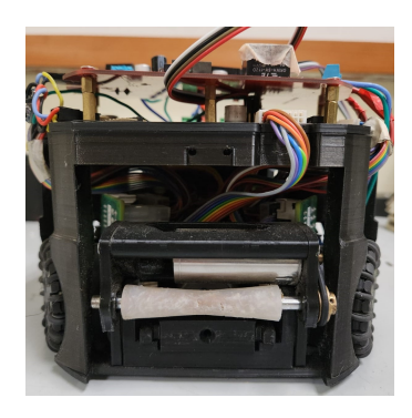
Our previous version, described in our 2024 TDP [1], featured a structure held together by two 3 mm-thick MDF discs. One of these served as the base of the robot, supporting all the components, while the other, located at the top, held the mainboard. From this point onward, these will be referred to as the bottom base and the top base for clarity. Although this technique worked well for us for years, issues arose as the repeated assembly and disassembly of the robot caused the screw holes to wear out (ass seen in Fig 1 and 2), necessitating the replacement of the bases. This problem, compounded by the breakdown of our university's laser cutter, led us to explore new approaches.
2 Hardware
This year, hardware modifications focused mainly on developing the kickboard, which underwent extensive testing to finalize its implementation, the development of this board began as part of the 2023 TDP [5]. In addition, a printed circuit board (PCB) was designed for the base station, which is used to send information to robots.
2.1 Kicker
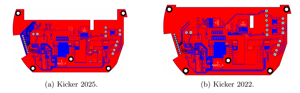
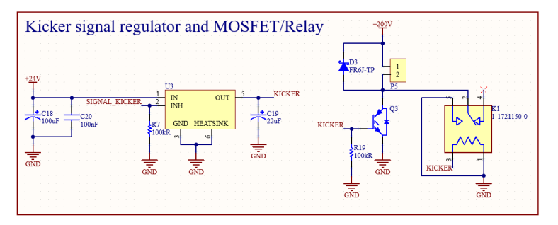
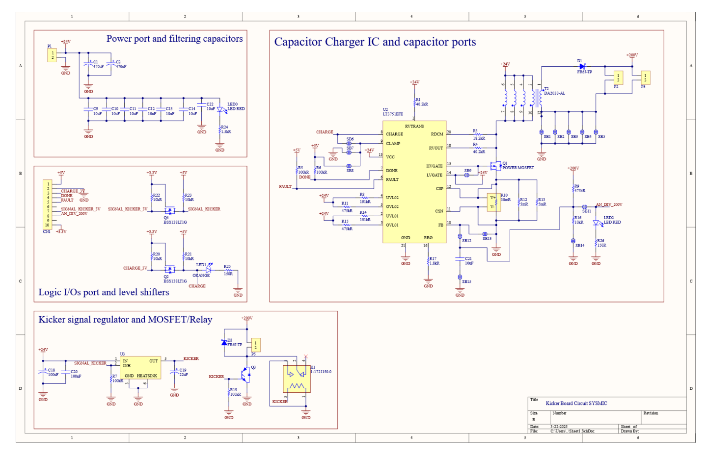
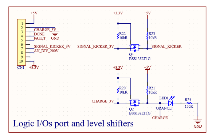
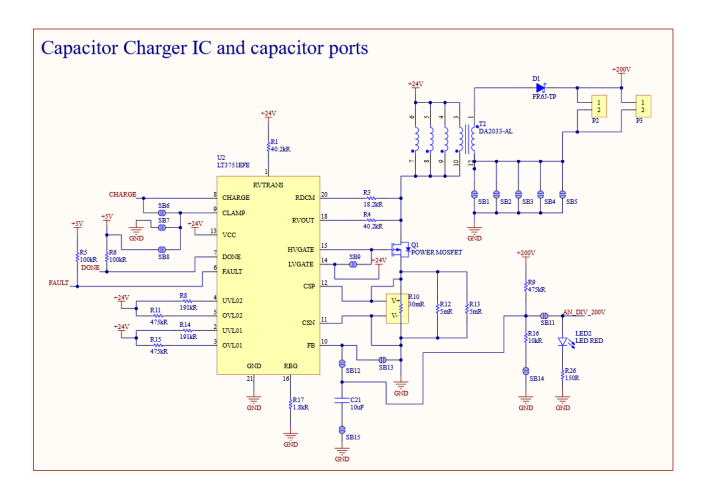
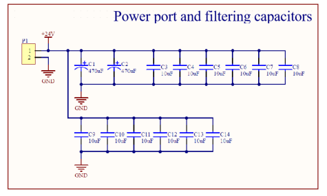
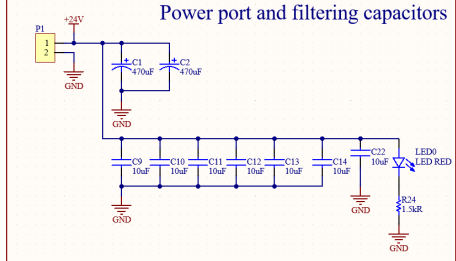
We conducted a thorough review of the kickboard, and we identified numerous unnecessary and redundant components, as well as several issues present in the first version of the board, which was introduced in the 2023 TDP [5]. Based on these findings, we designed a new board that eliminates these superfluous components and addresses the errors identified in the initial version, the new board schematics can be seen in Fig. 12, and a comparison between the layouts of the current and older version of it in 11. This optimization not only saved space within the robot but also enhanced its overall design and efficiency.
2.2 Base Station PCB Development
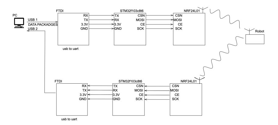
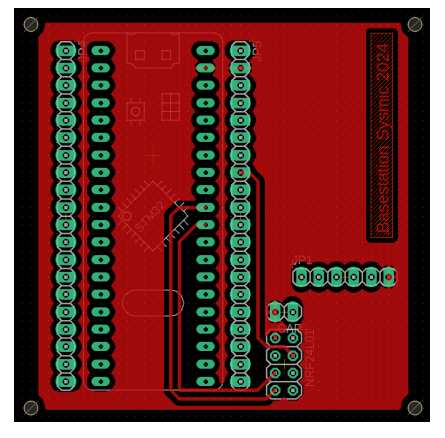
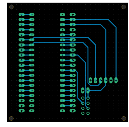
As part of our communication system, we developed the first version of the Base Station PCB, a key component designed to facilitate wireless data exchange between the control system and the robots. The board is built around an STM32 microcontroller, which interfaces with both an FTDI module for USB communication and an NRF24L01 radio module via SPI. Below, we present images of the Base Station PCB, showcasing both the top and bottom views of the board, where the key components and their layout can be observed. One of the main improvements in this design was the transition from a pre-perforated board, which was prone to failures due to weak solder joints and inconsistent connections, to a custom-designed PCB. The previous setup occasionally failed, causing communication issues that impacted system reliability. With this new PCB, we ensured a more robust and reliable platform. Additionally, the modular design of the board allows us to replace faulty components, such as the radio module or the FTDI interface, quickly and efficiently. This flexibility minimizes downtime and simplifies maintenance, making the system more adaptable and resilient in real-world conditions. This PCB represents a significant milestone in the team's development efforts, providing the foundation for a scalable and efficient communication system within the robotics platform.
Future Hardware Development (2025 and Beyond)
- Modular Mainboard: Redesign to isolate functional sections, preventing total system failure due to localized issues.
- Integrated Battery Monitoring: Add voltage indicators and alarms directly to the PCB.
- Rigorous Testing: Validate the kickboard and base station designs post-manufacturing to ensure compliance with performance standards.
3 Software
In previous years, we participated in competitions using software developed by other teams, specifically RoboJackets' software [4]. While this approach allowed us to compete, it limited our ability to customize and fully understand the underlying mechanics of the system. Therefore, our first major challenge is to develop our own software from scratch. This will provide us with greater control over the system, enable deeper insights into crucial aspects of the competition such as robot control, strategy, the graphical user interface (GUI), and a more structured and well-documented codebase. A robust codebase will make it easier for new team members to onboard, understand the system, contribute effectively, and become productive more quickly.
We selected Python for the initial prototype due to its flexibility and efficiency in developing. Our initial focus was on establishing fundamental software components essential for developing more advanced functionalities, such as equipping the robot with basic autonomy capabilities—executing commands like moving to specific field position or face target positions. After validating this first prototype, we migrated the logic to C++ for enhanced runtime performance and incorporated Lua as an embedded scripting language for building and managing our high-level strategies.
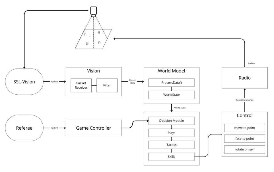
Software Architecture Our software development was inspired by the architecture of CMDragons [2]. We adopted key features such as modular task division and efficient state management. Figure 20 presents a diagram illustrating system architecture and explained in the followings points:
- Vision: This module receives and processes packets asynchronously from SSL-Vision. It employs a Kalman filter to reduce measurement noise and enhance positional accuracy, ensuring reliable and precise input for other system components. Due to the asynchronous nature of SSL-Vision communication, this module operates in a dedicated single thread.
- GameController: Similarly, the GameController module handles asynchronous communication with the SSL-GameController, interpreting game events and referee commands. It ensures compliance with game rules and enables appropriate responses to changes in the game state. To effectively manage these asynchronous communications, this module also runs in its own dedicated single thread.
- World: The World module receives processed data from the Vision module, including ball and robot positions and orientations. It also computes angular and linear velocities for each robot using the backward difference method. After processing, the World module updates and stores this information as the centralized repository for the current game state.
- Control: This component uses data provided by the World Module to enable robots to act autonomously. Specifically, it manages robot behaviors related to movements through simplified commands like "move to point" or "face to point," which abstract away complex underlying computations. To archieve these commands we employs the following algorithms:
- (a) Path Planning: Responsible for generating obstacle-free paths. Initially, we employed the RRT (Rapidly-exploring Random Tree) algorithm. However, the large number of edges in the generated paths caused issues for the control system. To address this, we adopted the Fast Path Planning [6] algorithm, which efficiently resolves this problem by producing smoother paths.
- (b) Motion Control: Responsible for actually executing movements along planned paths. Initially, trapezoidal velocity profiles were employed, but these caused the robot to pause at intermediate points, leading to nonsmooth movement. The team transitioned to BangBang Control [3], enabling continuous, fluid movements without unwanted stops. Additionally, we implemented a PID controller specifically for angular movements, greatly improving orientation accuracy (especially when executing commands such as "face to point").
- Strategy: For strategic decision-making, we adopted the Skills, Tactics, and Plays (STP) [2] . This structured, hierarchical framework allows clear, modular, and efficient strategy implementation. The Strategy module integrates directly with the Control module to execute low-level robot actions, referred to as "Skills." All the strategy logic is written in Lua.
- Communication Module: This module is responsible for transmitting the instructions generated by the control module to their respective destinations, whether to the simulator (grSim) or the radio system.
4 Firmware
4.1 Kinematic model
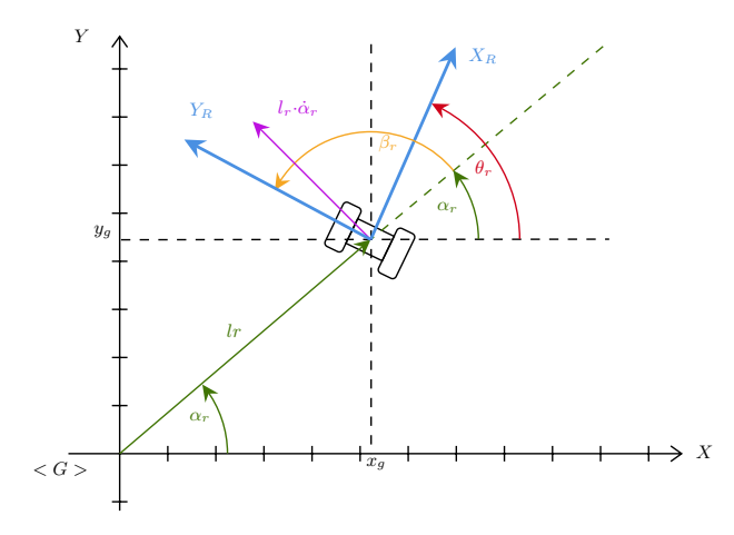
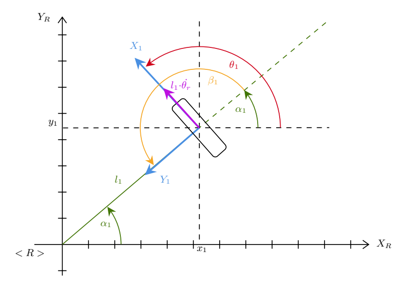
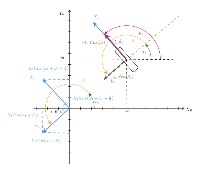
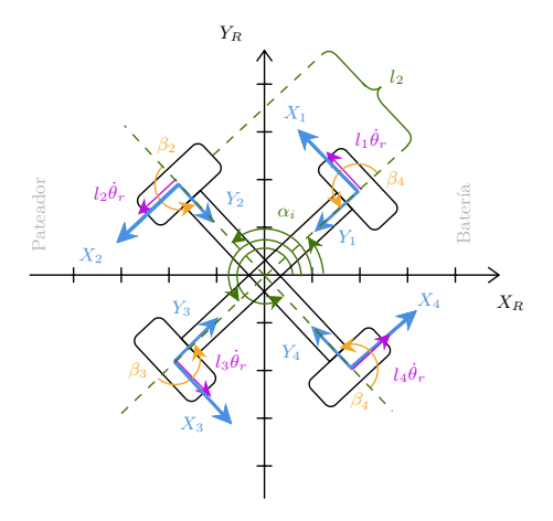
In recent years, we have consistently faced challenges in understanding certain models and design decisions implemented by former team members. These complexities were often difficult to articulate or clarify, even for those familiar with the project, as they appeared in the firmware code as a matrix that 'just works'. To address this issue, we developed a comprehensive and rigorous description of the robot's kinematic model based on the book Introduction to Autonomous Robots by Siegwart et al. [7], specifying the methodology by which the robot calculates the required velocities for each of its wheels, making this topic easier to explain and understand. In this section, we present a summary alongside diagrams.
References
- Arriagada, A., Cortes, N., Jimenez, I., Marihuan, G., Moya, D., Richards, I., Tapia, C., Valenzuela, C.: Sysmic Robotics - Team Description Paper 2024 (2024)
- Browning, B., Bruce, J., Bowling, M., Veloso, M.M.: STP: Skills, Tactics and Plays for Multi-Robot Control in Adversarial Environments (6 2018). https://doi.org/10.1184/R1/6561002.v1, https://kilthub.cmu.edu/articles/journal_contribution/STP_Skills_Tactics_and_Plays_for_Multi-Robot_Control_in_Adversarial_Environments/6561002
- Purwin, O., D'Andrea, R.: Trajectory generation and control for four wheeled omnidirectional vehicles. Robotics and Autonomous Systems 54, 13–22 (01 2006). https://doi.org/10.1016/j.robot.2005.10.002
- RoboJackets: Georgia Tech RoboJackets software for the RoboCup Small Size League (SSL) https://github.com/RoboJackets/robocup-software
- Rodenas, T., Torres, D., Reyes, P., Peña, J., Tapia, C., Moya, D.: Sysmic Robotics - Team Description Paper 2023 (2023)
- Rodríguez, S., Rojas, E., Pérez, K., López, J., Quintero, C.A., Calderón, J.M.: Fast path planning algorithm for the robocup small size league. In: Robot Soccer World Cup (2014), https://api.semanticscholar.org/CorpusID:12886519
- Siegwart, R., Nourbakhsh, I., Scaramuzza, D.: Introduction to Autonomous Mobile Robots, second edition. Intelligent Robotics and Autonomous Agents series, MIT Press (2011), https://books.google.cl/books?id=4of6AQAAQBAJ