TRAPS Team Description for RoboCup 2025
Ryoma Mitsuoka, Daichi Miyajima, Naoya Nishiura, Taisuke Tane, Hajime Teruoka, Yasutaka Tsuruta, Masahiro Uchida, Eiki Nagata, Ryuhei Fukuta, Satoru Sakakibara, Yusei Naito, Kai Inagaki
TRAPS; Nagoya University; The University of Tokyo
https://traps-official.web.app/
Abstract This paper describes the robot and software system developed by TRAPS, a RoboCup Small Size League (SSL) team aiming to compete in RoboCup 2025. First, we introduce the robot design and hardware configuration. We then propose a reinforcement learning environment to improve ball occupancy in SSL matches, as well as a path planning method designed to minimize collisions between robots.
Introduction
TRAPS is a RoboCup Small Size League (SSL) team established in the spring of 2024, mainly by former KIKS members. Our team consists of individuals with diverse backgrounds, including both students and working professionals. In addition to developing the technology and strategy for robot soccer, we strive to make robot competitions more appealing to a wide audience.
In 2024, we focus on participating in the official RoboCup competition for the first time in 2025. Starting in spring 2024, we created robots designed to participate in the official matches, and by February 2025, we had successfully completed several third-generation robots. In software system, we have developed a reinforcement learning environment to keep the ball in possession without losing it to the opponent robot. Furthermore, we proposed and implemented a new path planning method to minimize the number of collisions.
The remainder of this paper is structured as follows. First, Chapter 2 describes the mechanical system of the robot and efforts of the robot to make the robot competitions more popular. Next, Chapter 3 introduces electrical system. Chapter 4 then describes the reinforcement learning environment for ball retention, followed by a new path planning method in Chapter 5. Finally, conclusions are presented in Chapter 6.
Mechanical System
Our team members are dispersed throughout Japan, and most of our mechanical design and manufacturing is conducted online. In addition, in order to enhance the performance of the robot, it is essential to have a system that enables rapid response to updates and malfunctions. Therefore, we adopted a design approach in which mechanisms are divided and modularized to a certain extent to accelerate the PDCA cycle, enable short-run mass production, and facilitate quick component replacement in the event of issues.
Core Structure
In conventional small robot design, it has been common practice to pack a variety of mechanisms and wiring into a limited internal space to the utmost limit. However, such high-density and integrated structures make it difficult to access components for updates and repairs, and also complicate the manufacturing process. Therefore, we prioritize interchangeability and expandability over optimization, and have adopted an approach of dividing the mechanism into multiple units for each functional block. Specifically, we defined a drive unit, wheel unit, dribble unit, kick unit and electrical unit as independent units. Then, we designed them as detachable components so that parts can be exchanged and updated quickly. In addition, it is minimized the kinds of bolts used to attach these components. This procedure reduces the assembly man-hours and incorrect assembly risk, and also contributes to ease of maintenance.
In addition, with the recent rapid spread of 3D printers, it has become easy to prototype and implement complex shapes and somewhat unreasonable modularization, which were difficult to achieve with conventional metal fabrication. Since replacement parts can be manufactured immediately even if a part is damaged, it is possible to speed up the PDCA cycle, which involves frequent updates of designs for each module and repeated trial and error. In addition, our policy of minimizing the number of metal parts and actively introducing plastic parts has reduced manufacturing costs and weight. In this team's case, almost all parts other than the most heavily loaded parts, such as gears, motor mounts, and bottom plates, were manufactured using a 3D printer. The details are described in detail in the following sections.
Drive Unit
We use maxon 50[W] motors in direct drive. This saves space on the robot.
The motors are arranged differently at the front and rear of the robot, considering the space for the dribble unit and the lateral movement performance. Specifically, the front of the robot is opened 120° to provide space for the dribbling unit. In contrast, the rear of the robot is opened 86° to improve lateral movement performance as much as possible.
Wheel Unit
The small wheel mechanism consists of an O-ring structure with POM washers and a silicone tube cut to 1.8 mm. To reduce friction between the O-ring and the large tire, M3 washers are placed on both sides of the small wheel. The structure of the small wheel mechanism is shown in Fig.1.
In the conventional design (ICRS-FC 2022), each small wheel had a separate pin arrangement, which increased the number of parts and made maintenance more difficult. We addressed this issue by adopting a circular shaft. The shaft, made of ϕ2.6 mm aluminum, minimizes friction with the POM washers and is supported in such a way that prevents the ring from rotating, thereby preventing wheel detachment.
The entire wheel mechanism of the robot is shown in Fig.2. The large wheel is manufactured by 3D printing using PETG material, which is more efficient than metal manufacturing. Details of the materials and specifications of each component are shown in Table 1.
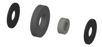
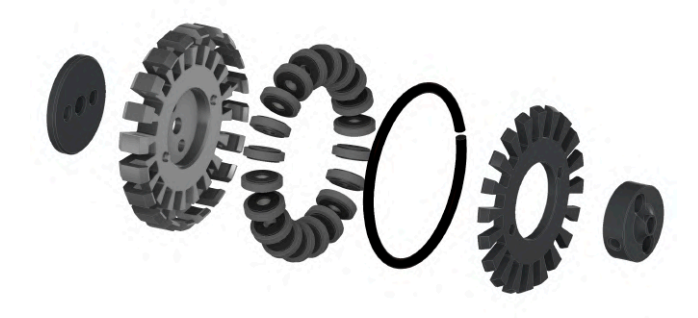
Table 1: Component Materials and Specifications of Wheel Assembly
| Component | Description | Material |
|---|---|---|
| Small Wheel | Main friction component | POM |
| O-ring | Contact surface with large tire | Silicon tube (1.8mm) |
| Washers | Friction reduction spacers | M3 steel |
| Shaft | Main axle for small wheels | Aluminum (2.6) |
| Large Wheel | Main wheel structure | PETG |
| Support Structure | Prevents ring rotation | Aluminum |
Dribble Unit
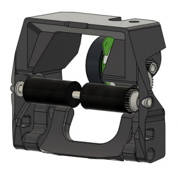
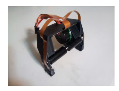
The dribble unit consists of a barrel, gear and motor for barrel rotation, ball sensors board, a rotating mechanism for shock absorption, and a frame to restrain them. The structure of the dribble unit is shown in Fig.3.
The barrel consists of a ϕ15 mm cushion with a 4 mm diameter stainless steel shaft. The cushion is removed 5 mm from the center to the left and right so that the ball can be held near the center.
A maxon EC-max 22 ϕ22 mm motor is used for the barrel rotation. Because of the large diameter of this motor, a gear with a large diameter was used for the intermediate gear of the three gears connecting the motor and the barrel shaft.
The rotating mechanism for shock absorption has a rotating shaft directly under the barrel, which moves back and forth when the ball is caught. This movement is expected to absorb the impact of the ball.
The frame of the Dribble Unit consists of a single 3D printed part. This eliminates the need for bolt connections between parts and is expected to reduce weight and improve serviceability.
Kick Unit
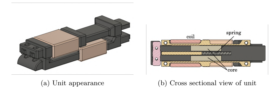
Kick Unit comprises two solenoids: one for straight kicks and another for chip kicks. The structure of kick unit is illustrated in Fig.4.
This unit is based on the solenoid utilized by KIKS[1], with the bobbin designed to have a square cross-section. To facilitate mass production, all components except for the coil, spring, and cores are fabricated using 3D printed parts made of PLA-CF.
Appearance
While it is obviously important to improve the competitiveness of the robots, we also emphasize the importance of "creating robots that will be cheered on". One of the differences between human soccer and RoboCup SSL is that it is difficult for spectators to become emotionally involved with the robots. While human players naturally develop emotions when they play hard, in the case of robots, it is difficult for people who are not involved in the design and programming to develop emotions toward the machines themselves during the competition.
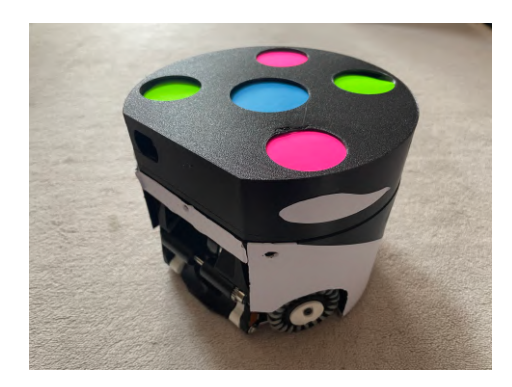
We decided to strengthen the "character" of the robots through exterior design and decoration. Specifically, the coloring and shape of the robot is inspired by our team's motif, the orca, as shown in Fig.5. In addition, the shape and color of the eyes have been changed to differentiate each robot, and in the future, our team is considering the possibility of incorporating a display to express emotions. In addition, the sponsor companies are also encouraged to add their own original corporate designs to each robot to increase their sense of belonging to our team and their attachment to the robot.
By focusing on the appearance, it is expected that both spectators and sponsors will view the robots as their own, leading to greater support and assistance. This will contribute to the excitement of the RoboCup, and the increased recognition will create a virtuous cycle that will lead to the development of robot technology and the establishment of a financial base.
Electrical System
Our electrical system is based on KIKS system[2][3], known for its high computational power and stability. However, as AI-driven strategy systems continue to evolve rapidly, there is a growing need for hardware advancements to keep pace with these developments. Therefore, our electrical system has improved its operational stability from KIKS system to accommodate more advanced AI strategies.
The system comprises four components: main board, kicker board, extension board, and IR board. In this chapter, we present a detailed overview of the enhancements introduced to each component.
Main Board
Main board is a core component for running the robot, handling communication with the software system and motor control. This board shares the same circuitry as KIKS[2], and we use a Jetson Nano as the MCU. However, we changed the Wi-Fi module from 8260NGW to intel AX200 to improve the wireless communication stability.
Kicker Board
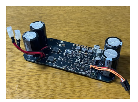
Kicker board controls solenoid drive. This board is based on the KIKS[3] board design and uses a circuit with enhanced noise immunity and reduced wiring. Specifically, we modified the GND pattern to improve noise immunity. To reduced wiring, we also modified the large capacitor for the solenoid drive to be connected with a board made of FR-4 material instead of a cable. Figure 6 shows our modified Kicker board. We believe this change reduces contact failures and improves stability.
Extension Board and IR Board
Extension board and IR board are developed by us. Extension board is connected to both main board and IR board, supporting the main boards operation. Specifically, it senses the ball, communicates with kicker boards, and controls LEDs and buzzers. IR board, which is equipped with infrared sensors for ball detection, is connected to Extension board.
In many SSL robots, the ball sensors are separate from the control board and attached to the dribbling unit. Therefore, it is necessary to connect the infrared transmitter side sensors, the receiver side sensors, and the control board.
Conventional SSL robots use two main types of connection methods, but both have their disadvantages. One connection method is to connect each sensors and board through wired cables. This method is simple, but requires wired cables to be placed outside of the dribble unit and carries the risk of wire breakage. Another method is to connect the infrared transmitter and receiver through boards made of FR-4 material and board to board connector, which is then connected to the control board with wired cables. This method is seen in TIGERs robots[4]. Although it reduces the risk of wire breakage by allowing the wired cables to be placed inside the robot, it requires modifications to the circuit board whenever the dribbling unit is changed. This limitation restricts design flexibility, which is particularly problematic in our case, as we frequently experiment with different dribble unit structures.
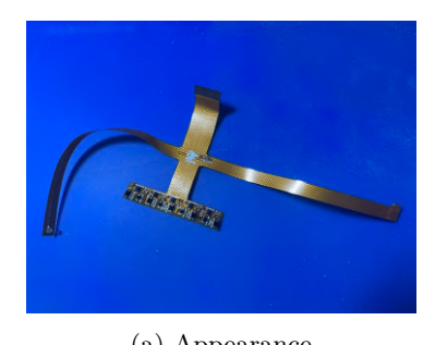
To solve the above problem, we mounted ball sensors on a flexible board and connected the board directly to the control board. Figure 7 shows the flexible board. This method allows ball sensors to be soldered to flexible board. In addition, flexible board can be directly connected to the control board via board-to-FPC connectors. In other words, it allows ball sensors to be mounted without wired cables, minimizing the risk of wire breakage. In addition, since flexible board can be bent freely, it is possible to respond to changes in the dribble unit by simply changing the way it crawls. Therefore, we adopted the use of flexible substrates because we believe that the problems existing in the above connection methods can be solved by using flexible board. IR board is currently fixed to the dribble unit with double-sided tape.
Reinforcement Learning Environment
In RoboCup SSL, decision-making requires considering multi-robot interactions, especially for ball-handling under physical constraints. To address this, we applied Multi-Agent Reinforcement Learning (MARL) [5] and developed a VMASbased environment with a dribbling mechanism. We evaluated MARL policies in Ball Replay and Ball Retrieval tasks, confirming that agents successfully learned ball control and strategic actions.
Selection of simulation environment
Challenges of previous methods Physics-based simulators such as Isaac Sim [6], Isaac Gym [7], are effective for simulating complex physical phenomena. However, their high-fidelity simulation makes it computationally expensive in multi-agent environments [8].
VMAS Adoption We employed a two-dimensional simulator (Vehicorized-MultiAgentSimulator, VMAS) that guarantees the minimum range of physical phenomena required for RoboCup SSL and is capable of massively parallel execution. VMAS is capable of interfacing with Bench MARL[9] and provides implementations of major MARL algorithms such as MADDPG[10], QMIX[11], and MAPPO[12].
Simulator Extension
Implementation of dribbling function The dribbling mechanism of the RoboCup SSL was implemented for VMAS. Specifically, the following algorithm controls the relative positional relationship between the agent and the ball:
In addition, we implemented a mechanism that releases the dribbling state in the following situations
- Detection of collision with other robots
- Exceeding the robot's speed and acceleration thresholds
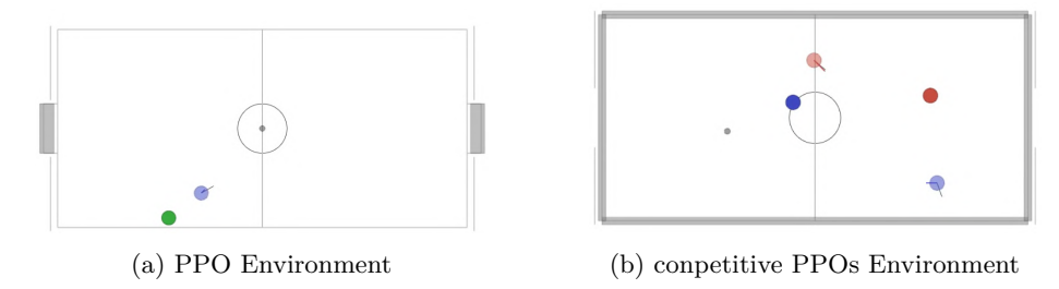
Table 2: Experimental configuration for Ball Replay Task
| Environment Settings | |
|---|---|
| Agents | Blue 1 |
| Reward Components | |
| rdist | Distance between agent and ball |
| rapproach | Alignment of agent movement with ball direction |
| rgoal | Progress towards target position |
| rdribble | Successful ball control |
| rtarget | Goal achievement state |
Table 3: Experimental configuration for Ball Retrieval Task
| Environment Settings | |
|---|---|
| Agents | Blue 1, Red 1 |
| Reward Components | |
| rdist | Distance between agent and ball |
| rapproach | Alignment of agent movement with ball direction |
| rgoal | Progress towards target position |
| rdribble | Successful ball control |
| rtarget | Goal achievement state |
Implementation Tasks and Evaluation Experiments
Experimental setup Figures 8a and 8b show the experimental environment. Under the settings listed in Tables 2 and 3, we employed PPO[13] for the single-agent task. For the multi-agent tasks, we adopted the competitive two PPOs, which also utilizes PPO for each agent optimization. In Fig.8a, the blue circle represents the agent, and the green circle indicates the ball replacement target location for this agent. In Fig.8b, the light blue and light red circles each denote an agent, and their respective darker-colored circles indicate the ball replacement target locations. In both environments, the gray circles represent the ball.
Ball Replay Task Figures 9a and 9b show the learning curves of the PPO in the ball replay task during training and testing. The rewards converged at a certain time step during training, and the same trend was observed during testing. During the learning process, the agent showed only simple approach behavior to the ball in the early stage of learning, but as the learning progressed, the agent was able to position the ball precisely. In particular, optimization of the approach angle to the ball improved the stability of the replacing action.
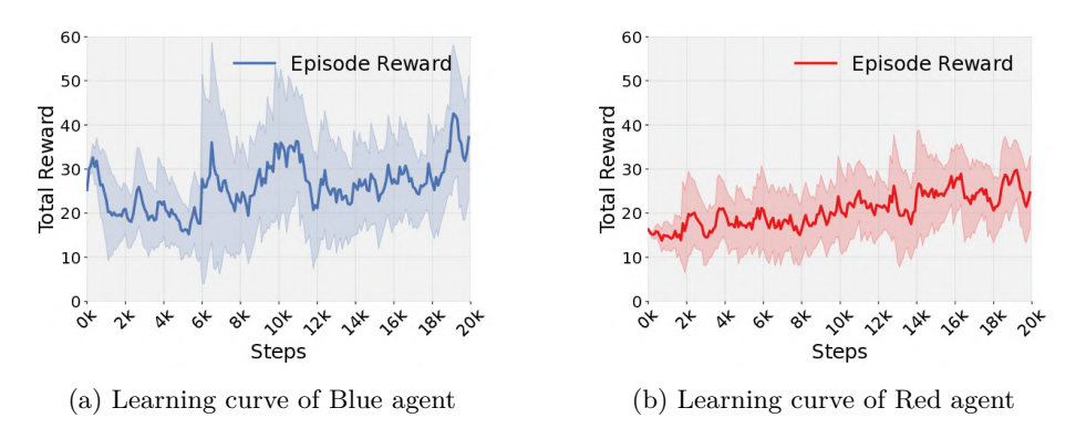
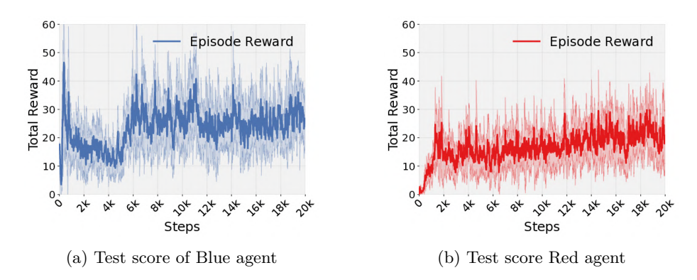
Ball Retrieval Task Figures 10a, 10b, 11a, and 11b show the learning curves for the blue and red teams during training and testing. The red team was trained in a competitive PPOs setting where the blue team was trying to achieve its goal while the red team was trying to interfere. Rewards for both teams improved steadily during training and converged at a certain time step. Similar trends were observed during testing, indicating the effectiveness of the measures acquired by both teams. Notably, learning converged more quickly than with a single agent, and the robot autonomously acquired the behavior of predicting the direction of the other robot's movement and selecting the optimal angle.

Path Planning with A* and Sampling-Based Approach
In multi-robot control, collisions between robots can cause hardware failures. Furthermore, in the RoboCup SSL, robot collisions may be considered fouls according to the competition rules. When fouls accumulate, the offending robot may be forced to leave the field, resulting in a significant strategic disadvantage. It is therefore crucial to minimize collisions whenever possible.
On the other hand, there are situations in a soccer match where robots may intentionally contact each other, such as contesting the ball or blocking. If collision avoidance is overly prioritized, aggressive plays may be compromised. Therefore, a path planning method that tolerates moderate contact while minimizing the risk of hardware malfunctions and fouls is required.
In this chapter, we present a path planning method that integrates a global planner and a local planner to ensure reliable arrival at the destination while achieving conditional collision avoidance. The global planner considers only static obstacles and determines long-term goals. In contrast, the local planner generates collision-avoidance trajectories by accounting for both its own dynamics and those of obstacles, thereby balancing safety and aggressiveness.
Approach
In our method, incoming commands are categorized into position and velocity commands. A position command is used directly as the goal, while a velocity command computes the goal from the target velocity. Next, an escape procedure checks if immediate collision avoidance is needed. If so, the corresponding velocity command is output immediately; otherwise, a global planner generates an intermediate sub-goal that a local planner refines to produce the final velocity command. The complete command processing is detailed in Algorithm 2.
Global Planner We employ the A* algorithm as the global planner to determine sub-goals for reaching destinations during the match. By leveraging heuristics, A* can efficiently find the shortest path. In our approach, the global planner recognizes only robots moving at low speed (effectively stationary) and off-limits areas (e.g., defense areas) as obstacles. Since a fast-moving robot will likely change its position significantly in a short time, it is not considered necessary to detour around it a few seconds later.
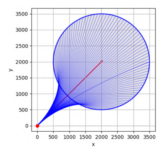
Local Planner The local planner is based on a sampling-based approach [14], which generates locally feasible paths while considering the robots dynamic properties. First, using the robots maximum speed and acceleration, we estimate the area that other robots can reach within N seconds (Fig. 12). Here, N is set to be longer than the time required to stop from its maximum speed. Next, we generate multiple candidate trajectories for our robot in a radial manner and evaluate their collision risks. Specifically, when the speed is low (below 700 mm/s), collision detection with obstacles near the goal is relaxed to suppress unnecessary avoidance maneuvers. Additionally, obstacles approaching from behind relative to the robots trajectory are not considered for avoidance, as they pose a low collision risk. The trajectory that best approaches the target state is then selected.
Experiments
Environment We conducted our experiments using grSim[15], a simulator for the RoboCup SSL. Two dynamic obstacle robots and two static obstacle robots were placed in the environment. The dynamic obstacles move along predefined trajectories, while the static ones remain in fixed positions.
Robots Two main robots were tested, each traveling to a goal located 2 m ahead. The robots have a circular shape with a radius of 0.09 m and a maximum speed of 2.5 m/s.
Methods
- Global Only: Using only Global Planner. All dynamic obstacles are input as static obstacles
- Local Only: Using only Local Planner
- Ours: Proposed method (combination of global and local)
Metrics
- Travel Time: The time from start to reaching the goal (in seconds)
- Collision Count: Number of collisions between robots and obstacle robots
Results
Each method was run for 20 round trips (total of 40 runs), and the mean and standard deviation were computed. Table 4 shows the evaluation results. The trajectories of the robots using our method are shown in Fig. 13. The Global Only approach demonstrated shorter travel times; however, due to insufficient local collision avoidance control, it resulted in frequent collisions with dynamic obstacles. In contrast, the Local Only approach completely avoided collisions but tended to incur longer travel times because of redundant detours. In contrast, our method successfully combines the advantages of both global and local strategies, significantly reducing the number of collisions while maintaining efficiency that surpasses that of the Global Only approach.
Table 4: Driving Performance Evaluation
| Method | Travel Time (s) | Collision Count |
|---|---|---|
| Global Only | $2.54 \pm 0.338$ | $1.60 \pm 0.928$ |
| Local Only | $2.93 \pm 0.116$ | $0.000 \pm 0.000$ |
| Ours | $2.41 \pm 0.813$ | $0.000 \pm 0.000$ |
Conclusion
This paper reports on the robot and software system we developed. In Chapter 2, modularized design was used to improve development efficiency, maintainability, and reliability. The exterior of the robot was differentiated by reflecting our team motif. In Chapter 3, based on the KIKS system, circuit stability was improved by enhancing noise immunity and reducing cables. In Chapter 4, we built a reinforcement learning environment using VMAS and confirmed the effectiveness of learning with MARL. In Chapter 5, we proposed a new path planning method that combines Global Planner and Local Planner, and confirmed that it significantly reduces the collision count while shortening the travel time.
In the future, in addition to further enhancement of the robot and tactical plan, we will work to grow the robotics competition into a more beloved content.
References
- Koh Ohno, Toshiki Mimura, Hayato Yokota, Tessen Ohmura, Tetsuya Sano, Masato Watanabe, and Toko Sugiura. KIKS 2017 Team Description. https://www.ee.toyota-ct.ac.jp/staff/sugi/KIKS2017TDP.pdf.
- Ryoma Mitsuoka, Yusei Naito, Yasutaka Tsuruta, Daichi Miyajima, Kosei Naito, Hironobu Suzuki, Ryuto Tanaka, Hayato Mitsuda, Yota Dori, and Toko Sugiura. KIKS Extended Team Description for RoboCup 2022. https://www.ee. toyota-ct.ac.jp/staff/sugi/ETDPfor2022RC_KIKS.pdf.
- Daichi Miyajima, Kosei Naito, Hayato Mitsuda, Kazuki Harada, Mizuki Nonoyama, Ryo Shirai, Futa Sato, Ryuto Tanaka, Yota Dori, and Toko Sugiura. KIKS Extended Team Description for RoboCup 2023. https://www.ee.toyota-ct.ac.jp/ staff/sugi/ETDPfor2023RC_KIKS.pdf.
- TIGERs MANNHEIM. TIGERs-MANNHEIM/electronics. https://github.com/TIGERs-Mannheim/electronics/tree/ 0c5389bc5ab02ce010c0de291e1ae1c4e74c8dfb.
- Jennifer Gielis, Ajay Shankar, and Amanda Prorok. A critical review of communications in multi-robot systems. Current robotics reports, 3(4):213–225, 2022.
- NVIDIA Isaac Sim. https://developer.nvidia.com/isaac-sim. Accessed: 2024- 01-25.
- Viktor Makoviychuk, Lukasz Wawrzyniak, Yunrong Guo, Michelle Lu, Kier Storey, Miles Macklin, David Hoeller, Nikita Rudin, Arthur Allshire, Ankur Handa, et al. Isaac gym: High performance gpu-based physics simulation for robot learning. arXiv preprint arXiv:2108.10470, 2021.
- Matteo Bettini, Ryan Kortvelesy, Jan Blumenkamp, and Amanda Prorok. Vmas: A vectorized multi-agent simulator for collective robot learning. In International Symposium on Distributed Autonomous Robotic Systems, pages 42–56. Springer, 2022.
- Matteo Bettini, Amanda Prorok, and Vincent Moens. Benchmarl: Benchmarking multi-agent reinforcement learning. arXiv preprint arXiv:2312.01472, 2023.
- Ryan Lowe, Yi Wu, Aviv Tamar, Jean Harb, Pieter Abbeel, and Igor Mordatch. Multi-agent actor-critic for mixed cooperative-competitive environments. In Advances in Neural Information Processing Systems, volume 2017-December, 2017.
- Tabish Rashid, Mikayel Samvelyan, Christian Schroeder De Witt, Gregory Farquhar, Jakob Foerster, and Shimon Whiteson. Qmix: Monotonic value function factorisation for deep multi-agent reinforcement learning. In 35th International Conference on Machine Learning, ICML 2018, volume 10, 2018.
- Chao Yu, Akash Velu, Eugene Vinitsky, Jiaxuan Gao, Yu Wang, Alexandre Bayen, and Yi Wu. The surprising effectiveness of ppo in cooperative multi-agent games. In Advances in Neural Information Processing Systems, volume 35. Neural information processing systems foundation, 2022.
- John Schulman, Filip Wolski, Prafulla Dhariwal, Alec Radford, and Oleg Klimov. Proximal policy optimization algorithms. arXiv preprint arXiv:1707.06347, 2017.
- Nicolai Ommer, André Ryll, Michael Ratzel, and Mark Geiger. TIGERs Mannheim Extended Team Description for RoboCup 2024, 2024.
- Valiallah Monajjemi, A. Koochakzadeh, and S. S. Ghidary. grsim robocup small size robot soccer simulator. In RoboCup, 2011.