The A-Team Team Description Paper 2025
M. Barulic, A. Chandani, C. Clark, R. Osawa, J. Spall IV, W. Stuckey, N. Witten, M. Woodward
The A-Team
Abstract "The A-Team" is a community team from the United States participating in our third year of RoboCup SSL. Our mission is to practice technical skills, inspire the communities in which we are present, and stay connected with friends around the world. This paper presents the work done since the 2024 TDP. Focus is placed on the development of our second generation competition-ready platform, ongoing improvements to the platform and software since the 2024 Eindhoven event, and exploratory work experimenting with novel approaches to SSL challenges.
Mechanical
Wheels
In previous years, the robot drivetrain utilized off-the-shelf 50 mm wheels from GTF ROBOTS [4]. The use of an off-the-shelf solution helped to reduce the time required to deploy a full fleet of robots. As other parts of the software, electrical, and mechanical systems matured, priority could be switched to designing custom wheels to improve the quality and reduce the compensation required by the other systems.
The primary objective of the redesign was to resolve two particular issues: effective diameter and roller precision. The previous wheels had an advertised diameter of 50 mm, but the individual rollers had roughly 1 mm of tolerance, which resulted in an effective diameter of 48 mm before any rubber compression. Since the wheels are in a direct-drive configuration with a motor with max diameter of 45 mm, the ground clearance was significantly reduced, leading to unintended carpet drag that increased the burden on the control system to properly compensate. The rollers in the previous wheels were also toleranced such that the rollers could pivot about 13 degrees within each roller slot, causing inconsistent traction.
The new design targets a 60 mm diameter and tightens the final tolerances to fractions of a millimeter. Since these wheels will be assembled by the team, ease of assembly and maintenance were also considered. The final design consists of a 3-D printed base, an aluminum cover plate, a wheel adapter, and 21 rollers. Each roller consists of a 3-D printed core, a stainless steel dowel pin, and a Shore 70A O-ring. Component details are captured in Table 1.
The base component for the wheel contains all of the detailed features required to constrain the rollers. This allows for all other components to remain simple. The use of the heat set inserts also allows the cover plate to be mounted securely without the risk of plastic threads or the use of loose nuts.
The rollers have a simple construction with only 3 components: a dowel pin, a roller core, and a rubber O-ring. The roller core has a 2 mm diameter hole in the center, which interfaces with an undersized dowel pin with a tightly toleranced diameter between 1.986 and 2 mm. This allows for a robust yet smooth rolling motion.
The cover plate is required to be both stiff and robust in a thin form factor. As such, the use of aluminum was chosen over a 3-D printed solution. In addition, this component was ordered as an aluminum PCB in favor of a cut sheet metal service to save on cost while adding the ability to add notes on the silkscreen layer.
The wheel adapter allows for a robust connection between the wheel and the motor shaft while still maintaining the ease of assembly and disassembly. The design was primarily based on the TIGERs Mannheim's wheel adapter [11] modified to allow mounting with a set screw instead of an adhesive.
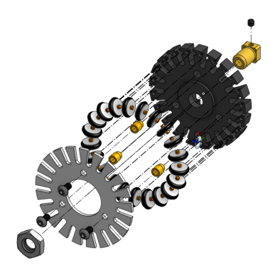
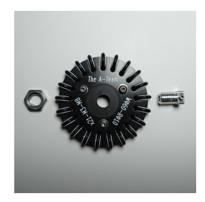
The individual components of the wheel are shown in Figure 1. The manufactured wheel shown in Figure 2 had a diametric accuracy within 0.5 mm without rubber compression. The total cost per wheel at quantity 50 comes to roughly 8 USD. The cost is dominated by the custom machined adapter, which accounts for 7 USD. The aluminum PCB (cover plate) at this quantity was less than 1 USD per piece. The PLA material cost, fastener cost, and rubber O-ring costs were negligible. Compared to the 35.00 USD price point of the off-the-shelf option, this custom solution is more economical.
Wheel Parameters
| Roller Count | 21 |
|---|---|
| Wheel Diameter [mm] | 60 |
| Wheel Thickness [mm] | 10 |
| Wheel Base Material | PLA |
| Cover Plate Thickness [mm] | 1.6 |
| Cover Plate Material | Aluminum |
| Roller Core ID [mm] | 2 |
| Roller Core Thickness [mm] | 2.8 |
| Roller Core Material | PLA |
| Roller Rubber OD [mm] | 10 |
| Roller Rubber ID [mm] | 6 |
| Roller Rubber Material | Neoprene |
| Roller Rubber Hardness | Shore 70A |
| Adapter Thread | M8-1.25 |
Pressure Gradient Dribbling Device
In the previous year's TDP, the static pressure requirement (492.0 Pa) was explored [3] to realize a dribbling apparatus utilizing an air pressure gradient as its primary mechanism. Here, the duct parameters will be explored.
In this particular application, there is one inlet (ball interfacing side), one outlet (fan interfacing side), and a negligible height difference between the two. As such, a simple duct model can be applied to obtain rough estimates of the fluid dynamic interactions. In this model, there are two particularly relevant equations to characterize the fluid dynamic interactions - Bernoulli's equation (Equation 1) and the continuity equation (Equation 2). Together, these equations show the relationship among pressure (P), air velocity (V), cross-sectional area (A), and ρ (air density).
$$P_{outlet} + \frac{1}{2}\rho V_{outlet}^2 = P_{inlet} + \frac{1}{2}\rho V_{inlet}^2$$
$$V_{outlet} * A_{outlet} = V_{inlet} * A_{inlet}$$
Combining the two, the dynamic pressure drop across the duct can be calculated using Equation 3. Since the upper bound for the inlet area will be constrained to the 34.13 mm effective diameter limit [3], using an off-the-shelf fan such as a 40 mm x 40 mm fan will yield an outlet area larger than the inlet area. The outlet-to-inlet area ratio will be greater than unity, which yields a lower pressure at the inlet compared to the outlet. Furthermore, as the inlet becomes increasingly occluded (inlet area decreases) with the ball, the inlet air velocity increases, and as a result, the inlet pressure decreases. This is highly advantageous, as the ball that becomes partially captured will further decrease the pressure on the side facing the dribbling apparatus, creating a steeper pressure gradient that applies a higher net force to push the ball towards the center of the dribbling apparatus.
$$P_{inlet} - P_{outlet} = \frac{1}{2} \rho V_{outlet}^2 \left(1 - \left(\frac{A_{outlet}}{A_{inlet}}\right)^2\right)$$
In conclusion, as long as the frictional losses are negligible, the duct design can be flexible, as the outlet-to-inlet area ratio is guaranteed to be favorable. Future design considerations include the integration of an impact damping mechanism and the integration of a traditional roller-based dribbling apparatus. The integration of a traditional roller-based dribbling apparatus is particularly interesting, as it may open up top spin as a new dynamic in the game.
Electrical
Modular Design
This year's electrical revision has emphasized modularizing the major electrical subsystems. This was driven by two main factors: mechanical flexibility and the cost of revisions. The architecture of the previous two years, 2023 and 2024, was fairly monolithic with most communications, body control, motor control, and power conditioning being on one PCB and kicking functionality being on a second PCB. The mechanical flexibility drawbacks were being locked into a very specific mechanical layout of full robot diameter, and board ordering for radio access. This limited room for other features the team wanted to explore such as larger wheels, an air dribbler and other dribbler revisions, and a future onboard expansion of compute power. A more substantial drawback was the cost of ordering all of the boards every time there was a revision and the complete loss of a board when sporadic failures happen. An example was ongoing reliability issues with the digital power switch (now resolved in the Power Board section) on the control board. Fixing the bug required re-purchasing parts and assembly for the motor controllers and main microcontroller, which is a substantial cost. By splitting control, motor-controller, and power board apart we gain flexibility to partially iterate each year at reduced cost and layout labor. As a self-funded team whose members work full-time jobs, both of these are major factors in our choices.
A common electrical interface was chosen for inter-board communication. The common interface includes 3.3 and 5.0V power, uart, flow control, reset, and a GPIO. The uart, reset, and GPIO can be used to make stm32 MCU's enter the bootloader, allowing for firmware programming chaining. The motor controller interface is the same, but adds 4A continuous battery supply to additional pins. Because uart is ubiquitous in MCUs (which can serve as bus adapter and subprocessors) we can easily substitute out any specific subsystem with another on the same connector.
Power Board
The team designed a new power board to provide all key voltages and protections to the entire robot from one place. This reduces duplicate regulation across different boards and adds safety features to the robot. The new power board minimum specifications can be found in Table 2. The power board contains the following safety features:
- Over-voltage and under-voltage protection, over-current protection
- Battery and cell health monitoring (lagging cell, dead cell, out-of-spec)
- Battery percent remaining
- Audible alarms and LEDs for error conditions
- Management interface including outbound power-down commands, inbound power-down requests via serial/SPI/I2C
- Programmable power on and power off rail sequencing, error detection
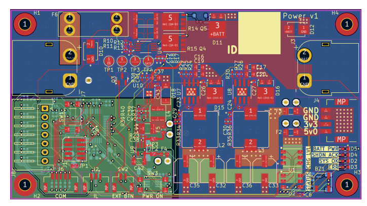
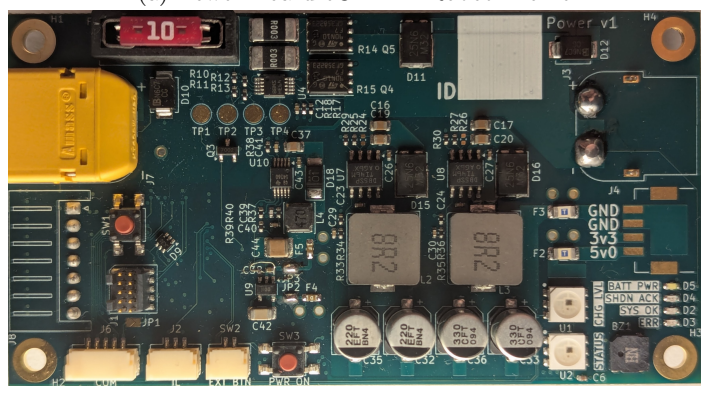
This power board revision also fixes errata related to the use of a power protection IC not-rated for hot-plug events. We discussed the challenges with this in previous TDPs and have finally resolved them fully with this design [3]. The team selected the LM5069 as power protection IC explicitly rated for hotplugging events and have not observed any issues on hot plug [16]. A hot-plug capable power IC was selected after reviewing RoboTeam Twente's RoboCup 2024 Poster [1]. The board design can be seen in Figure 3.
Power Board Specifications
| Parameter | Value | Notes |
|---|---|---|
| Vin Max | 36V | Currently 25.2V (6-cell LiPo) |
| Vin Min | 7.5V | Currently 16V (6-cell LiPo) |
| Vin Iout Max (cont.) | 35A | Configurable |
| 5.0V Iout Max (cont.) | 5A | Configurable |
| 3.3V Iout Max (cont.) | 5A | Configurable |
| Max Battery Cell Count | 6 | Range: 1-6 |
Motor Controllers
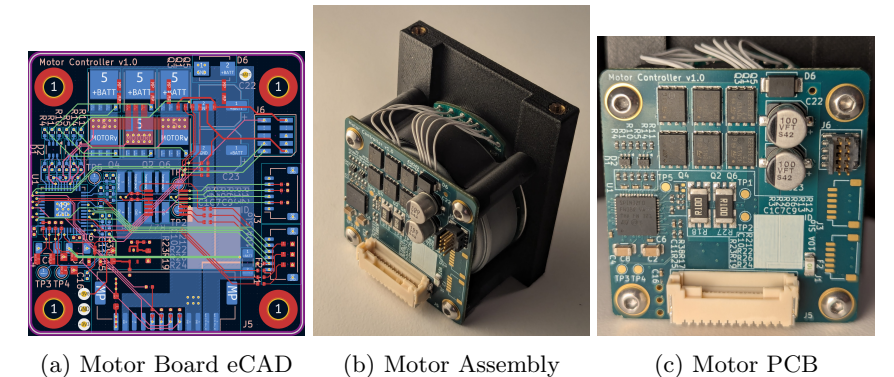
As part of the push to modularize the electrical system, the motor controller sub-circuits from the previous control board were built into standalone motor controllers. This has the benefit of being more easily replaceable during competition if something breaks and also removes the cable between the encoder and microcontroller. Although we have error detection in place for unplugged or broken encoder cables, this makes the likelihood of a runaway control loop due to encoder miscommunication substantially lower. This was one of our primary hardware faults in 2024, occurring twice in the calendar year. Additionally, the team redesigned the current sensing amplification and over-current protection circuity to widen the sensing range outside of the motor's nominal parameters. This allows for greater flexibility in the control envelope. This was done by increasing the sense resistor value, and increasing the package size to allow for more current and less thermal drift. Overall sensitivity and thermal margin was approximately quadrupled. A dedicated 3.0V linear regulator provides clean stable power to the analog network compared to the noisier 3.3V switching supply. Prototype artifacts of the new motor controllers can be seen in Figure 4.
Motor Controller Specifications
| Parameter | Value | Notes |
|---|---|---|
| Vmotor Max | 28V | Currently 24V |
| Vmotor Min | 12V | |
| Vmotor Max (cont.) | 40A | Currently 10A |
| Drive Modes | - | 6-step, sensored FOC |
| Safety | - | Voltage, Current, Torque |
Optical Flow
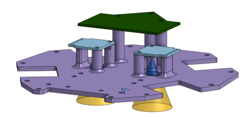
In previous years, the team has explored using optical flow motion sensors as alternative methods for verifying body velocity [2, 3]. We continued experimenting with the PAA5100JE-Q [10] optical flow tracking sensor, utilizing the Pimoroni off-the-shelf breakout board [9]. We designed a companion PCB to collect and translate the sensor values into movement coordinates for sending up to the control board. We also created a new version of the base plate for motion testing with the sensors integrated. Initial testing indicated that the sensor continued reporting values even while the sensor had slightly varying heights due to natural texture of the carpet. However, more substantial testing with full system integration is required for determining reliability and error in a competition environment.
Intelligent Firmware Flashing
One challenge with complex multi-microcontroller systems is the need to program many firmware images and verify the state of the entire system. Our robots previously programmed the motor controller firmware from the primary microcontroller during every boot sequence, whether or not they were still up-to-date. This guaranteed we booted into a known state, but often wasted time when the team was making minor or rapid changes to firmware or when we needed to turn on and switch out a bot quickly during a match. This year, we reduced the time needed to have a turned on bot be ready by adding a mechanism to check whether or not the motor controller firmware is up-to-date using git metadata. The latest git hash and dirty status of the working tree when the firmware was built is embedded into both the main board and the motor controller binaries. On boot, peripherals report their embedded git status to the main microcontroller which can make an informed decision on whether an update is required. If there is a git hash mismatch or if either party's binary was built using a dirty git working tree, the motor controller will be flashed. Otherwise, the firmware loaded on the motor controller is guaranteed to be synchronized, and this step can be skipped, expediting the boot process. Although it is unlikely to be limiting factor, flash does have a limited number of write cycles, so this approach also improves the lifetime of the system.
Subtle Lessons Learned
The team includes this list of subtle lessons learned because we feel that they greatly improved our system reliability and were poorly documented in external resources.
Latching Connectors
The team originally used the JST SR series [6] connectors due to their small size, but we found that in the heat of competition and practice, we were too likely to pull the wires to remove the headers, causing long-term unreliability. We have switched to the JST GH [5] and JST ZE [7] series for most harnesses. We do not crimp our own wires within the harness, we purchase pre-crimped wires or pay LCSC to construct harnesses [8].
TVS Diodes
The team places TVS diodes on all user-facing IO (buttons, programming headers) and all ADC pins, as these have been found to be sensitive to motor-induced inductive spikes and other difficult-to-measure transient events.
Soldering Modern Voltage Regulators
The team has repeatedly tried using modern regulator options in an attempt to reduce the physical footprint of power generation subsystems. These regulators tend to utilize higher switching frequencies and advanced current-sensing heuristics to lower the inductor size, often the dominant factor in the overall footprint size. We have found these regulators are particularly sensitive to hand soldering and the amount of solder used on the thermal/ground EPAD. The team has seen this sensitivity on the LT3751, LT3504, LTC3864, and the LTC3636. We have used some of these parts with identical schematics in professional settings with full processional PCBA with no problems. We have observed modifying the amount of solder on EPAD (up or down) resolves instability issues. We confirmed with micro-probing that instability is not the result of an internal or bottom-side EPAD short or open connection. Voltage is produced at or around the correct level but with additional ripple and out of tolerance DC offset (e.g. 20mV on good placements, 50-100mV on poor placements, 200-300mV on extremely poor placements). The team recommends others commit to using full professional PCBA, full stencil reflow equipment, or using lower switching frequency, less integrated solutions. The team has gravitated toward the latter for cost and ease of manufacturing.
Motor Fusing
If motors are fused individually to protect against stalls and shorts, a TVS diode should be placed after the motor fuse to avoid a large negative inductive spike if the fuse blows at high current.
Software
Much of the software work in the final lead up to the 2024 Eindhoven RoboCup event focused on adding basic passing capabilities to our gameplay code. One of the more interesting challenges in passing is choosing where to place the receiving robot. Since the Eindhoven event, we have implemented a major change to our receiver placement technique. We have also published a new open source package to help teams using ROS connect to SSL league servers.
Pass Receiver Placement
Positioning a robot receiving a pass is interesting in part because it must consider both how the ball will get to the robot and what the robot will do with the ball after the pass completes. It is challenging because it is essentially an optimization problem over the full area of the field. For the Eindhoven event, we used a simple placement method which was fast to implement but severely limited the placement options. Since then, we have implemented a new heatmapbased approach which allows for more intelligent placement while maintaining performance through GPU-based computing.
Lane-Segment Approach
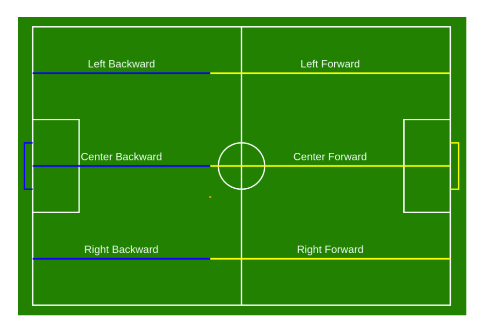
Our old approach generated six segments on the field, found a point along each segment as a passing candidate, then chose the best of the six points to be the pass target. Figure 6 shows the segments rendered on a field. The field is divided into three lanes which each cover a third of the field's width. The center line of each lane is split into two segments: one forward of the ball and one behind the ball.
Passing quality is evaluated with a system we call the window evaluator. A window is a range on a segment with continuous line of sight to the source. For each lane segment, one pass of window evaluation is applied to find the largest window on the segment using the ball as the source. The midpoint of this window becomes the candidate pass target. Then another pass of window evaluation is performed from the candidate pass target to the opponent's goal. The quality metric used to compare the six candidate pass targets is a mixture of the widths of the intermediate and goal windows.
It is possible for the entire lane segment to be blocked by the opponent team. In this case, the midpoint of the lane segment is used as the candidate pass target and a minimal quality is assumed. Similarly, if there is no window on the goal from the candidate pass target, a minimal quality is assumed.
While this approach is easy to implement and fast to execute, it has limitations in real gameplay. Because selection of the candidate point on each lane segment does not consider quality of the shot on goal, situations can regularly arise where a better pass target exists along the lane segment which is not the midpoint of a window. This is not a surprising result as this is a coarse approach to what is fundamentally an optimization problem. Despite these limitations, we found it to be effective enough to setup opportunities for shots on goal at the 2024 Eindhoven event. Unfortunately, independent issues with our kicking skill prevented our team from executing on these opportunities after passing the ball down field successfully.
Heatmap Approach
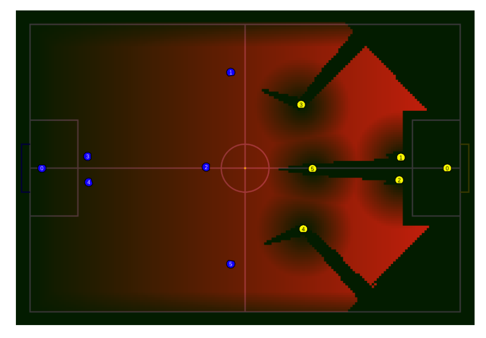
Many tasks in a Small Size League game are fundamentally an optimization problem over the space of the field. Our team envisions moving to a centralized and performant spatial evaluation module in our software whose results can be used by plays, tactics, and other components in our gameplay software. The intent is to allow solving these complex optimization tasks without repeating computation across different multiple parts of the software. We have begun evaluating this approach by implementing a basic prototype of the spatial evaluation system to solve the pass receiver placement problem. The output of this prototype is a heatmap of the field where higher values indicate better pass receiver candidate locations.
Figure 7 shows the rendered heatmap generated by the spatial evaluation prototype against an example scenario. The heatmap defines a grid over the field and each cell value in the grid is calculated from a mixture of multiple layers. There are two types of layers: binary and floating point. Binary layers act as masks in which each location on the field is either allowed or disallowed. Floating point layers allow for weighting locations on the field with scoring functions.
In the pass receiver placement prototype, we use four mask layers:
- Line of sight to the opponent's goal
- Line of sight to the ball
- Exclusion of the boundary area around the field
- Exclusion of the opponent's defense area
The prototype also uses three floating point layers:
- Distance down the field
- Distance from the edge of the field
- Distance from opponent robots
These floating point layers are mixed to determine the final floating point value used to score each location. The mixing involves clamping individual layers to certain maximum values, then multiplying the layers together. The passing play then chooses the location with the largest value as the passing target, breaking ties arbitrarily.
While our simulation and lab testing has already demonstrated qualitatively better pass target selection, we have further improvements planned before bringing this system to the 2025 Salvador event. One aspect of receiver placement that is not considered in the current system is the quality of the shot on goal. It ensures the receiver has line of sight on the goal, but that line of sight may be through a narrow gap between defenders. An improved system would include a weight layer based on the width of the visible goal area to prefer wider shots on the goal. We also intend to incorporate this general spatial analysis approach in other parts of our gameplay code, so it will need to be optimized to run quickly on many tasks at the same time. The process of generating and mixing the heatmap layers is very similar to other forms of image generation and manipulation. We expect its performance to benefit greatly from a GPU-enabled implementation.
SSL ROS Bridge Nodes
One of the first software challenges new SSL teams must tackle is interacting with the league servers, particularly the vision and game controller servers. For teams using the Robot Operating System (ROS), it would be convenient to interact through ROS topics and services without having to handle the protobuf messages and low-level networking details. To assist in this, we have published the ssl ros bridge packages. These packages provide ROS nodes which map SSL multicast streams to ROS topics and expose team client interactions as ROS services.
The ssl ros bridge repository includes four ROS packages:
- ssl league protobufs includes the SSL league protobuf definition files and builds them into a library other packages can consume.
- ssl league msgs provides ROS interface definitions which mirror, as closely as possible, the SSL protobuf messages.
- ssl ros bridge msgs provides ROS interface definitions used by ssl ros bridge which have no direct protobuf equivalent.
- ssl ros bridge provides the ROS nodes and launch files. This package is the main one users interact with.
The ssl ros bridge package provides three nodes:
- vision bridge node converts multicast messages from the vision server to a ROS topic.
- gc multicast bridge node converts multicast messages from the game controller server to a ROS topic.
- team client node connects to the game controller as a team client and exposes ROS services for making requests such as changing goalie ID and bot substitutions.
This is the same code our team has been using to connect our ROS system to the league servers. We have repackaged it to make it easier for other teams to consume. Our own software stack now depends on this new repository, so we can commit to keeping it maintained. We hope other SSL teams using ROS will find this package useful as a tool to lower the barrier of entry to participating in the league. The published software can be found in our team's GitHub organization [15].
Open Source
Mechanical, electrical, firmware, software, and control and circuit models are published on the team's GitHub page and licensed for broad use [12, 14, 13]. Competition versions are documented with known issues and production artifacts for full replication. Software currently supports the latest Ubuntu/ROS LTS. Mechanical, electrical, firmware, and controls currently support most modern operating systems.
References
- van der Kaaden et al., B.: Roboteam twente division a poster 2024 (2024)
- Avidano, C., Barnette, S., Barulic, M., Medrano, L., Neiger, J., Osawa, R., Peterson, E., Spall IV, J., Spalten, J., Stuckey, W., Woodward, M.: The a-team technical description paper 2023 (2023), https://ssl.robocup.org/wp-content/uploads/2023/02/2023_TDP_The_A_Team.pdf
- Avidano, C., Barulic, M., Clark, C., Osawa, R., Spall IV, J., Stuckey, W., Woodward, M.: The a-team technical description paper 2024 (2024), https://ssl.robocup.org/wp-content/uploads/2024/04/2024_TDP_The_A_Team.pdf
- GTF ROBOTS: 50mm Diameter 4mm Hole Size Omni Wheel, https://gtfrobots.com/product/50mm-diameter-4mm-hole-size-omni-wheel/
- JST: Product Series - GH Connector (2025), https://www.jst.com/products/crimp-style-connectors-wire-to-board-type/gh-connector/
- JST: Product Series - SR/SZ Connector (2025), https://www.jst.com/products/insulation-displacement-connectors-wire-to-board-type/sr-sz-connector/
- JST: Product Series - ZE Connector (2025), https://www.jst.com/products/crimp-style-connectors-wire-to-board-type/ze-connector/
- LCSC: LCSC Custom Cable Service (2025), https://www.lcsc.com/customcables
- Pimoroni: PAA5100JE Near Optical Flow SPI Breakout (2025), https://shop.pimoroni.com/products/paa5100je-optical-tracking-spi-breakout?variant=39315330170963
- PixArt: PAA5100JE-Q (2025), https://www.pixart.com/products-detail/74/PAA5100JE-Q
- Ryll, A.: Wheel adapter (2022), https://github.com/TIGERs-Mannheim/mechanics/blob/master/v2022/PDF/11_Radadapter.pdf
- The A-Team: SSL-A-Team Onshape 2024 Robot (2024), https://cad.onshape.com/documents/75f8983195cd6d66fab4fcd9
- The A-Team: SSL-A-Team GitHub Organization (2025), https://github.com/SSL-A-Team
- The A-Team: SSL-A-Team Onshape 2025 Robot (2025), https://cad.onshape.com/documents/2eeb704b914dc4eea021eab8
- The A-Team: ssl ros bridge GitHub repository (2025), https://github.com/SSL-A-Team/ssl_ros_bridge
- TI: Texas Instruments LM5069 - 9-V to 80-V hot swap controller with power limiting (2025), https://www.ti.com/product/LM5069