2025 Team Description Paper: The Bots
Mathew MacDougall, Henry Bryant, Akhil Veeraghanta, Vikram Bhat, Ashley Lee, Steven Guido
github.com/sfunderbots · cad.onshape.com/documents/f50de4495ca6813b0d6d1926
Abstract This paper details the design and development of the systems of The Bots, a Small Size League team intending to compete in RoboCup 2025 in Salvador, Brazil. As well as improving the modular low-cost design from last year, we introduce safety features for our chicker board, and vision filter improvements.
Introduction
The Bots is an interdisciplinary team composed of university graduates who were formerly part of the UBC Thunderbots Design Team, as well as having recruited graduates from other Universities in the USA. Established in 2022 after RoboCup in Bangkok, Thailand, the team is now pursuing its first competitive action (after withdrawing from the 2024 competition) within the Small Size League seeking qualification for RoboCup 2025. One of the barriers of entry into the league is the development cost. The Bots has come up with a cost-optimized design, describing multiple optimizations for the league. As our mechanical systems have generally stayed consistent with last year, this paper outlines The Bots' progress in developing the electrical and software systems of these robots to compete in RoboCup 2025.
Electrical
Electrical System Overview
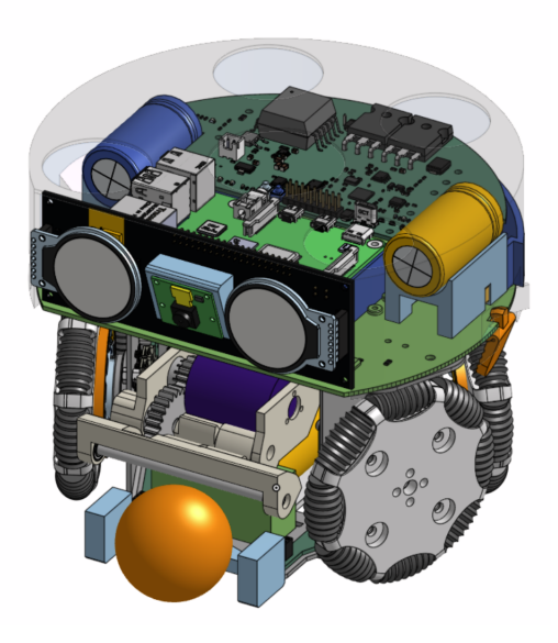
Since a large part of the electrical system was developed in the previous year, our main focus for this year has been the integration of the electrical and mechanical systems, on the robot itself rather than in design. All of our board projects[9], have been integrated into our working robots, with our 30 dollar motor drivers being the key integration to lower the cost of our robot, adhering to our $500 budget per robot we set last year. Besides the integration, there have been some improvements and new additions to the design of our electrical stackup this year, including a simple breakbeam design using off-the-shelf components, and improving the robustness for the chicker board. There are other minor improvements and validations, which will be covered in the following sections.
Chicker Board
While testing the chicker board V1.0 last year, we encountered voltage spikes, over-current issues, as well as flyback charging sensitivity. These issues and solutions will be discussed in the following sections.
Power Input Protections
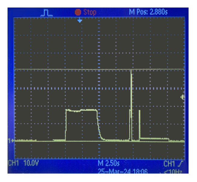
During testing last year, we saw a 40V spike travel to the board from a faulty power supply, shown in figure 2.1. This would prove that the input to the chicker board is not protected from voltage spikes. Since the chicker board is designed to run hand-in-hand with the midplate we designed, this should not be an issue in realistic testing scenarios. However, this voltage spike could be mitigated by adding a TVS diode to clamp the voltage if we are testing without the midplate.
Since this issue (above) showed up when trying to recreate an issue where gate driver chip would burn up from seemingly no outside interaction. There are two possibilities: one is caused from charging while kicking and the flyback transient energy, and the other due to the faulty power supply. In the test, the battery was plugged in while the logic level circuits were already functioning which caused the gate driver chip to burn up.
While it is generally not a good idea to send a charge cycle at the same time as a kick, we think this is not the cause of the problem; however it is a possibility that the transient energy from simply charging the high voltage rail could disrupt the chip operation. When a charge cycle is started, there is a large transfer of transient energy that can impact the voltage of the battery (see figure 2.1 between the 3rd and 4th grid intersection) since it draws large amounts of current. Having a tuned RCD snubber could help dissipate the excess energy due to leakage inductance and other factors, but including a 12V DC/DC converter would also likely help (this was cut due to size constraints). This was solved through the power board firmware to never charge when kicking and vice versa, but will hopefully be solved in hardware in the future.
The other likely cause of this problem (and maybe the more likely cause) is that the faulty power supply used in the test above was the culprit for this issue, which could have caused a smaller overvoltage condition (one that wasnt noticed, just barely exceeding the chip's ratings[2] of 20V), which would have then caused the chip to burn.
Logic Protections
Likewise, the logic level signals to the RP2040 are not protected from voltage and current spikes. For example, in the event of a long or non-deterministic pulse width sent to the gate driver, the IGBT would break from drawing too much current sent through the solenoid. Due to this large draw of power, the gate driver can pull too much current from the microcontroller, and break the pins connected. To solve the logic signal pins getting damaged we added 3v3 Zener diodes [1] to protect the logic level circuits, including: KICK, CHIP, BKBM, 5V_LEVEL, BATT_LEVEL (and any other important feedback pins).
Flyback Circuit Protections
There has been talk about the LT3750/51 silicon chips having non-deterministic voltage runway at high charge currents as well as some undisclosed sensitivity in differing temperature. Since the UBC Thunderbots power board design[3] has been largely stable, having the high voltage capacitors explode due to overvoltage at Robocup Eindhoven last year does cause unease. We think this occurrence might be due to sensitivity to temperature and humidity as the venue in Eindhoven was known to be very hot with very little air conditioning.
In the datasheet for the LT3751[4] they mention that the primary inductance and the output voltage are intricately linked (page 16), and if this relationship is not met (or if the inductance changes significantly) it could cause a runaway condition and it would overcharge the output capacitor. This follows by saying that the flyback charging design relies on having a low leakage inductance path, but will still work in "adequate" conditions. With the increase in temperature, this may well cause an increase in leakage current and possibly change the leakage inductance of the board, which would cause either thermal or voltage runaway depending on what was the cause.
As the caps on UBC Thunderbots Power board (and ours) are rated for 250V, the safety margin is only about 3% since their power board charges up to 240V. Ideally, the voltage rating margin should be at least 25% above the maximum voltage. In this light, we decided to use 200V as our maximum, which should easily be able to achieve the same outcome in kick speed. This will eventually be modelled in simulation to verify if we are to achieve this, but we should be able to do real world tests by changing a single resistor. Changing Rvout to 40.4k will make sure the output voltage charges to only ≈ 200V (using the same equation as last year[9]).
High voltage feedback was also added to the design for v1.1 based on UBC Thunderbots[5], with an op-amp to maintain low loss from the voltage divider. Zener diodes were also added to protect the low voltage circuits in case of a failure. The software would then be able to detect if the voltage is either too high, shutting off the charging and triggering a discharge (and possibly flag a fault), or have a sense of how much power one could generate in the fluctuation in the capacitor voltage based on how often we have decided to charge the system.
Software
Over the last year our primary focus has been on improving our supporting systems rather than gameplay strategy itself. These improvements include the ability to log and replay visualizations of our AI, trajectory planning based on Mannheim's trajectory sampling [6], and vision filters. This section highlights our innovative methods for testing and developing new vision filters.
Vision Filter Test Suite
Accurate vision filters are essential for accurately estimating the state of the ball and robots, which in turn leads to more consistent gameplay performance. Vision filters can be difficult to develop because they are difficult to test.
With sufficient field space and a camera setup, tests can be done manually. While the results will be representative of reality, the downside is that doing these tests in-person is time-consuming and not always consistent. Furthermore, there is no ground-truth data to compare against so evaluating the results is empirical. On the other hand, synthetic test data can be generated by creating ground-truth data and applying noise similar to SSL Vision. This test data can be used to create unit tests for the vision filters that are fast and repeatable. However, it is difficult to manually create test data that accurately captures the more complicated interactions between the ball and robots for more advanced test cases, resulting in gaps in test coverage. An example of a scenario that is difficult to model manually is how a high-speed ball bounces off a robot, or how the ball moves when being dribbled.
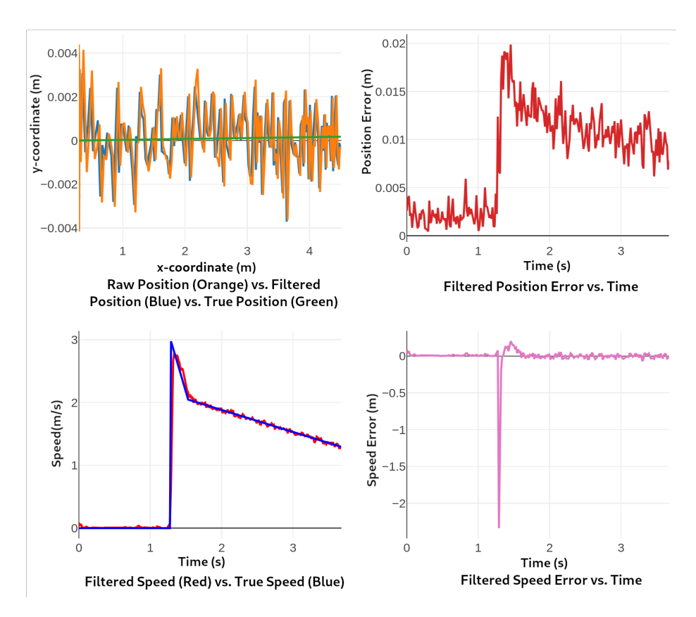
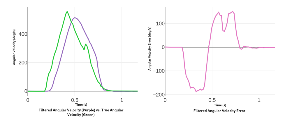
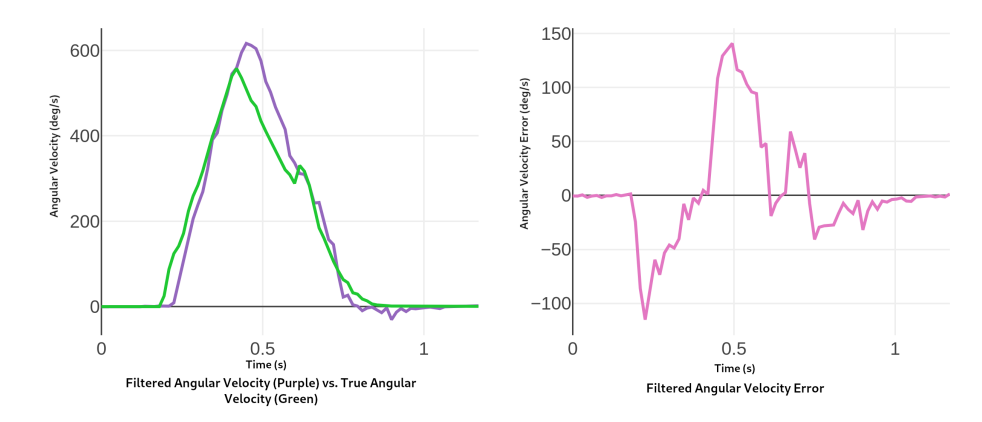
To address the shortcomings of these testing options, we have created a solution that combines the best of both. The fundamental idea is that we use a simulator to accurately model our testing scenarios, and use the simulator to output both ground-truth data and raw vision data. We log the data so it can be stored in our GitHub repo and loaded for each individual unit test. The raw data is fed into our filters, and the output is compared against the ground truth data to generate metrics on the filter error. Our tests assert the error values are below acceptable thresholds, and also generate plots showing the raw data, filtered data, and ground truth data. The assertions ensure that we do not accidentally regress the filters while developing or making changes, and the plots are indispensable for empirical validation and debugging. Examples of our error metrics are shown in figure 1, and example plots are shown in figure 3.1.
Technical Details We modified the Er-Force simulator to output the internal simulation state, which we use as ground-truth data, using the SSL Vision TrackerWrapperPacket. This effectively makes the simulator also act as a Tracker implementation, which is useful both for generating test data and running our AI with "perfect" vision information. When running simulation scenarios to generate the test data, running the AI with perfect tracked vision is important because it decouples the AI behavior from the performance of the vision filters.
Error values for a robot filter test where the robot rotates 180 degrees while stationary
| Abs Error | Mean | Median | p10 | p75 | p95 | max |
|---|---|---|---|---|---|---|
| Position (m) | 0.0013 | 0.0013 | 0.0005 | 0.0019 | 0.0026 | 0.0031 |
| Speed (m/s) | 0.0032 | 0.0026 | 0.0004 | 0.0039 | 0.0094 | 0.0168 |
| Orientation (deg) | 2.9279 | 2.1067 | 0.2703 | 5.0498 | 7.8971 | 8.7300 |
| Angular Velocity (deg/s) | 62.0006 | 8.7729 | 0.2004 | 134.4705 | 178.4893 | 187.4116 |
Our simulated test setup largely follows the ideas outlined by TIGERS Mannheim in their 2022 TDP [7]. We keep our vision filter test suite separate from our AI test suite since their configurations needs to be independent, such as the filter test suite needing to use tracked vision.
We have created separate test suites for the robot and ball filters. Each aims to cover all the basic actions and interactions that can be observed by the filter. Some examples are included below.
Robot Filter Test Scenarios (non-exhaustive)
- Stationary robot
- A stationary robot moves in a straight line to a target, without rotating
- A stationary robot rotates 180 degrees
Ball Filter Test Scenarios (non-exhaustive)
- Stationary ball
- The ball rolls to a stop
- A fast-moving ball collides with a robot's dribbler. This is done both for when the ball is visible the entire time, and when the ball is occluded by the robot before it collides.
- A robot pushes the ball forwards using it's dribbler. The ball starts as visible, and then becomes occluded by the robot
- A robot receives the ball in its dribbler, then rotates with the ball until the ball is occluded
For the ball filter in particular, some of these test scenarios were inspired by the edge cases and heuristics discussed by ER-Force in their 2023 TDP [8]. Our filter implementation is the same: A Kalman Filter, with additional heuristics that activate to handle specific scenarios that the Kalman Filter struggles with such as dribbling and ricochets.
Automated Parameter Tuning Having a suite of unit tests for the vision filters provides all the expected benefits: it gives us confidence while making changes and refactoring, and we can easily add additional scenarios for regression testing if we find new cases the filter does not handle well.
However we can take this one step further and use our test suite to automatically tune our filter parameters to optimize performance. To do so we turn the filter performance into a simple optimization problem. We define a function that takes the error output from a test, and returns a cost value (where lower is better). Then we can apply an optimization algorithm of our choice that minimizes this cost function within the parameter space of the filter. Since our filter is based on a Kalman filter, most of these parameters are the various process and measurement covariance values.
For example, this is the cost function used to tune the orientation-related parameters for the robot filter: It is a weighted sum of the mean, median, and max error values for both the orientation error and angular velocity error.
$$\sum_{all\ test\ scenarios} w_1 \theta_{mean} + w_2 \theta_{median} + w_3 \theta_{max} + w_4 \dot{\theta}{mean} + w_5 \dot{\theta}{median} + w_6 \dot{\theta}_{max}$$
During our tuning we put the most weight on reducing the median error since this correlates with reducing the error for the most frames in each test scenario, and generally optimizes the nominal performance. Over-indexing on the max error did not yield good results since there are cases where instantaneous changes briefly result in some expected error, and nominal performance was significantly degraded attempting to significantly reduce the error for these short periods.
Our parameter space is small enough for us to perform a brute-force search for optimal values. We have not evaluated alternative optimization algorithms at this time.
Error values for a robot filter test where a stationary robot rotates 180 degrees, using initial hand-picked parameters
| Abs Error | Mean | Median | p10 | p75 | p95 | max |
|---|---|---|---|---|---|---|
| Orientation (deg) | 2.9279 | 2.1067 | 0.2703 | 5.0498 | 7.8971 | 8.7300 |
| Angular Velocity (deg/s) | 62.0006 | 8.7729 | 0.2004 | 134.4705 | 178.4893 | 187.4116 |
Error values for a robot filter test where a stationary robot rotates 180 degrees, using parameters found by automated tuning
| Abs Error | Mean | Median | p10 | p75 | p95 | max |
|---|---|---|---|---|---|---|
| Orientation (deg) | 1.8365 | 0.8525 | 0.1228 | 3.0658 | 5.7519 | 6.7576 |
| Angular Velocity (deg/s) | 30.2773 | 8.8000 | 0.5132 | 44.3600 | 115.2885 | 141.3537 |
Conclusion
In this TDP we presented further improvements to our low-cost robot design and core software systems. The electrical systems have been verified and improved by adding better safety margins and protections. Our vision filters are significantly more robust, with test coverage that enables us to confidently make changes and automatically tune parameters for better performance. CAD files for our mechanical design are available on OnShape, and the robot firmware and electrical designs are available on Github.
References
- BZT52C3V3T-7 Zener Diode 3.3 V 300 mW, https://www.diodes.com/assets/Datasheets/ds30502.pdf
- MCP14A0454 Dual Mosfet Driver, https://ww1.microchip.com/downloads/en/DeviceDoc/20005985A.pdf
- Almoallim, A., Sousa, C., Sturn, D., Antoniuk, D., Crema, F., Bryant, H., Lew, J., Liu, J., Wakaba, K., Bontkes, L., Zhou, Y.: 2022 Team Description Paper: UBC Thunderbots (2022)
- Analog Devices: LT3751 - High Voltage Capacitor Charger Controller with Regulation, https://www.analog.com/media/en/technical-documentation/data-sheets/LT3751.pdf
- Dumitru, P., Ellis, G., Fink, J., Hers, B., Lew, J., MacDougall, M., Morcom, E., H., S., Sousa, C., Van Dam, W., Whyte, G., Zhang, L., Zheng, S., Zhou, Y.: 2020 Team Description Paper: UBC Thunderbots (2020)
- Nicolai Ommer, André Ryll, M.R.M.G.: Extended Team Description for RoboCup 2024 (2024)
- Ommer, N., Ryll, A., Geiger, M.: Extended Team Description for RoboCup 2022 (2022)
- Paul Bergmann, Theresa Engelhardt, E.G.U.H.T.H.V.H.R.M.F.M.M.S.M.S.M.S.A.W.M.W.: Extended Team Description Paper (2023)
- Veeraghanta, A., Bryant, H., Zheng, S., MacDougall, M., Lee, A., Guido, S., Bontkes, L., Van Dam, W.: 2024 Team Description Paper: The Bots (2024)