TritonBots FC 2025 Team Description Paper
Raymond Rada, Terri Tai, Daniel Bonkowsky, Pedro Pinela
University of California, San Diego, Institute of Electrical and Electronics Engineers
Abstract This paper describes the development of our overall robot design, including developments over the past year and the assembly of functional autonomous robots aiming to compete in the 2025 RoboCup Small Size League tournament in Salvador, Brazil. This year's development added more capabilities to our robots. These include, but are not limited to, improvements to the offensive and defensive positioning and formation algorithm, ball placement, smooth deceleration, switching platforms from Raspberry Pi to ESP32, a full mechanical design rework, development of PCBs, and accurate PID tuning. We continued to prioritize improving basic functionality before complex tasks.
1 Introduction
The 2025-2026 season is the Tritons' fifth attempt at participating in the RoboCup Small-Size League competition. The hardware and software leads joined in the fall of last year, working together to improve the structure of the team. This change allowed us to engineer and develop the most functional robots in our program's history. There have been redesigns to the mechanical design of the dribbler, kicker, and chassis of the robot, steady development on PCB and kicker driving circuit design, porting code to ESP32 for more efficient programming, and performing body-to-wheel velocity calculations on the ESP32. Our AI continues to utilize a Behavior Tree instead of a Skill System this year and has been given improvements to basic robot functionality [1].
2 Mechanical Design
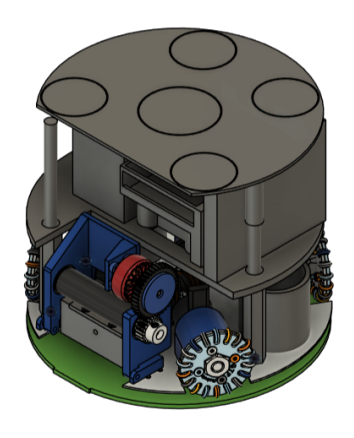
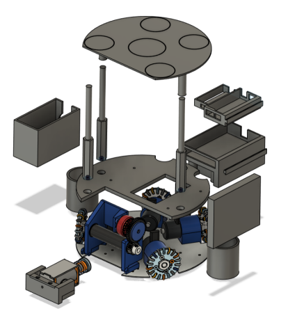
The robot has 2 layers to house components for the major functions of the robot; general movement, kicking, and dribbling. The first layer consists of the base plate to which wheels, motors, and the kicker solenoid are mounted. Above this lies the second layer, a plate mounted to the base plate which carries the dribbler system, and all of the electronics. All 3D-printed parts were manufactured using standard PLA.
2.1 Chassis
The base plate was designed to fit the necessary constraints of a competition robot in size and diameter. A circular plate was modified with specific slots to be cut for the placement of the wheels and kicker. The angles of the front wheels are aligned 30 degrees from the horizontal of the robot with the rear wheels aligned 60 degrees from the horizontal. From our research of other teams in the Small Size League, this configuration was selected for more efficient movement in the forward direction.
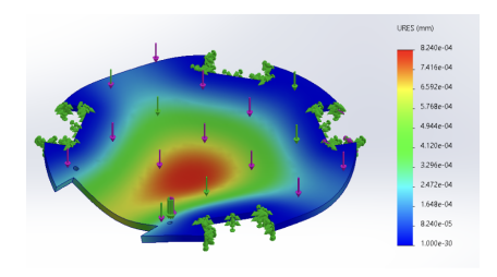
To reduce the power consumption of the robot, we determined it would need the lightest and most resistant material to deflection. With our general layout finalized, several virtual deflection analyses were performed in order to determine the material to use based on our criteria. In order to reduce weight while maximizing stiffness, 4.09-mm thick aluminum alloy was selected to be laser cut.
2.2 Dribbler
For robot possession of the ball, the dribbler subsystem relies on spinning the ball towards the robot. This solution has been adopted by all teams in the league. We implemented this design using a simple gear train that transfers power to the roller. A 2:1 gear ratio was designed for higher speed and more space-efficient component placement. The assembly is mounted on a pivot to allow for damping of the subsystem. By having the height of the dribbler slightly shorter than the optimal height for contact with the ball and the kicker, gravity and tension are applied to the ball. This gives the robot more traction with the ball, preventing it from slipping away while rotating. The XING-E Pro 2207 Motor was selected for its small dimensions, low weight, high speed, and immediate availability. Through testing, the optimal RPM of the motor was determined for minimal power consumption and sufficient control of the ball.
2.3 Kicker
The kicker is composed of 4 distinct components: One solenoid, two base mounts, a kicker plunger, and a kicker bracket. The FJ-Z05 solenoid is the only aftermarket component not designed by the team. The mechanism functions through the pushing force of the solenoid, which drives the kicker plunger and the plate to strike the ball. A bearing slider system was designed to minimize friction and align the plunger so that it's oriented parallel to the ground. The solenoid is fixed to the chassis through the base mounts, located on the sides of the solenoid parallel to the shaft.
3 Electronics
[Electronics section introduction - see subsections below]
3.1 PCB Design
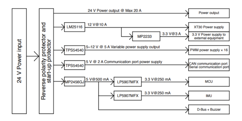
To step away from using over-the-shelf components and transition into a modular and customizable system for future work that contains the necessary peripherals and power outputs needed to drive our robot. We are currently reverse engineering a development board [RoboMaster Development Board Kit Type A] that was used for previous iterations of our robot to determine the layout and necessary ports for the current prototype.
After acquiring the schematic for the development board and the power tree, aspects of power systems, IO ports, and communication ports needed for operation of the robot were implemented in the PCB. Additional footprints were designed for the motor and speed controllers used for dribbling and movement.
A footprint for the C610 Robomaster motor controller to integrate it into our custom PCB. The motor controller was applied directly to the main PCB and improved overall board organization. Through analyzing the C610 datasheet/user guide, the necessary dimensions of the C610 were found to factor in the 3-phase cable port, power supply terminals, and CAN cable. Similarly our ICQUANZX BLHeli S6s 35A electronic speed controller for dribbler motor control was added to the PCB using the same methods.
3.2 Kicker Circuit
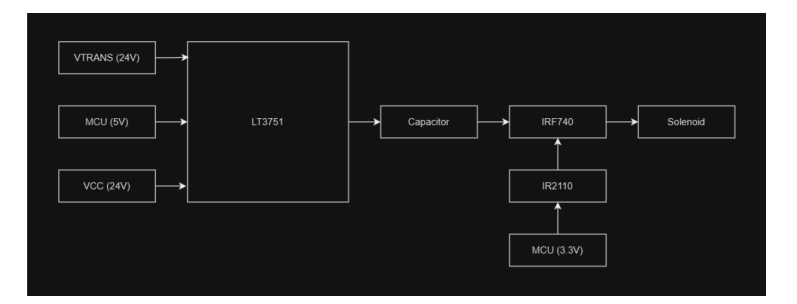
The kicker circuit operates by charging a high capacitance capacitor then quickly discharging through a solenoid linear actuator, allowing the mechanism to kick with high impulse. Key design considerations include minimizing size, safe operation, maintaining reliability under repeated high-voltage switching conditions, and minimal charge time.
Our implementation utilizes the LT3751 Capacitor Charger IC with the 42A Capacitor Charger application detailed in the datasheet [2]. This application was selected because of its low charge time at high voltages and capacitances. The output voltage of the circuit could also be set, allowing adjustment of the electric potential energy in each kick. For fast switching, we utilized the IRF740 power NMOS driven by the IR2110 low side MOSFET gate driver with decoupling capacitors for noise reduction.
For circuit protection, it was deemed necessary to read the capacitors fully charged prior to kicking. The LM393 comparator IC was utilized to apply an output voltage when the capacitors were detected to be fully charged. This logic high would then be fed into the microcontroller to indicate full charge. Additionally, a metal oxide varistor was applied in parallel with the NMOS to protect against voltage transients and active current limiter circuit for overcurrent protection.
Our next steps involve fabricating a custom solenoid that best meets size and force parameters and electrical characteristics along with completing the PCB design to house other necessary functionalities for the robot.
4 Embedded Systems
The embedded systems team is responsible for the integration of hardware and software on the robots. Our goal is to establish a robust network of communication between the electronic systems which control the motors and other actuators of the system and the software which controls the high-level decision making for the robot.
4.1 ESP32
A major change we implemented this year was moving our Body-to-Wheel velocity calculations to an ESP32 rather than a Raspberry Pi. Previously, each robot had an onboard Raspberry Pi that acted as a UDP server to receive data sent from the TritonSoccerAI client. Our new system uses ESP32s on each robot that act as the UDP servers to receive data from TritonSoccerAI and perform the velocity calculations. This change was made primarily due to the high overhead and power consumption of Raspberry Pis [5]. Our robot could not remain active for the full 5-minute half of a RoboCup match, and we needed to improve the overall power usage of the bot. A Raspberry Pi 4B will consume 540 mA (2.7 W) of power in idle state. An ESP32 in Active Mode, receiving data, will draw 95-100 mA (0.33 W) of power [6]. Although power consumption was our central reason for switching microcontrollers, the simplicity of the ESP32s made them much more behaved and easier to work with, and it was a very beneficial switch.
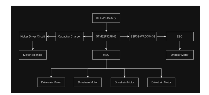
We are using ESP32 Development Boards with a USB Type-C connector and a CH340C USB to serial converter. The board works with an ESP32-WROOM-32 module. Each board is mounted on a robot and acts as a UDP server, receiving instructions about both movement and the kicker. The movement instructions are in the form of a vector in the global space, which the ESP32 converts into individual RPMs for each of the 4 wheels. The kicker instructions take the form of a flag, on or off, corresponding to whether the robot should be kicking or not.
The old code on the Raspberry Pis was written in Python and had to be migrated to C++ to run correctly on the ESP32s. The main difficulty in this migration was that Protocol Buffers (Protobuf), the serialization method we used to send data from our TritonSoccerAI client to the Raspberry Pi, is less well-defined for systems with tight memory constraints like the ESP32. As a solution to this, we used the Nanopb library, an implementation of Protobuf that is specifically designed for memory-constrained systems.
The rest of the code migration was relatively simple. The ESP32s receive the Protobuf data, decode it using deserialization code generated by Nanopb, convert global velocities into wheel speeds, and then send that data to our RoboMaster Type A Development board, which controls the motors and PID loop. For the velocity conversions, congruent math libraries exist in Python and C++, and minor error fixes were made. The Espressif Systems ESP32 Library has robust functionality for sending data via UART, so the ESP32 code ended up being more concise than the original Python code on the Raspberry Pi.
4.2 Other Hardware
The other important hardware components used by the embedded systems team are RoboMaster Type A Development boards with an STM32 chip, RoboMaster C610 Brushless DC Motor Speed Controllers, and DJI RoboMaster M2006 P36 Brushless Motors. The ESP32 receives data from TritonSoccerAI, processes it, and sends it to the RM Dev Board which sends speed values to the Motor Speed Controllers and performs PID tuning.
5 Software
[Software section introduction - see subsections below]
5.1 Offensive Positioning
The objective of this algorithm is to move the fielder to an advantageous spot on the field to increase the team's overall chance of shooting the goal, while the other fielders move to guard foes and maintain an open trajectory.
This algorithm is designed to generate a plan for all ally fielders, and execute it for our specific fielder. It should be run repetitively during offense, as it assumes and depends on the positions of the enemies, the allies, and the ball.
For each fielder robot f, define a circle C$^f$ centered around its current location with radius r in which it can move (so that its displacement is realistic given the time span where the game conditions don't change too much). Uniformly sample n (currently taken as $\pi r^2 / 1000$) points, $v_1^f, v_2^f, \ldots, v_n^f$, in C$^f$ for each robot f as candidate vertices.
First, determine the most hopeful trajectory. In this case, a hopeful trajectory would be a close proximity to a desired location like the goal or an ally.
Given a path from the ball to the gate P, we give a score to P in the following way:
$$reward = \frac{5000}{d(P, \text{enemies})} + \frac{10000}{l(P)}$$
Here, $d(P, \text{enemies})$ denotes the closest distance from any enemy to the path; $l(P)$ denotes the total length of the path.
We find a "good" trajectory, in other words, a successful pass with no obstacles, from the ball to the gate by choosing the path with the highest reward from the following configurations:
- Let the robot in possession of the ball be f0. We consider all straight lines from any of $v_i^{f0}$ to the gate.
- For each fielder $f \neq f0$, we consider the two-part jagged line from any of $v_i^{f0}$ to $v_j^f$, and then to the gate.
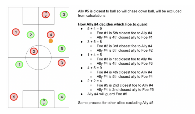
After this, we should have assigned one (if a type-1 path wins) or two (if a type-2 path wins) fielders to the trajectory. We assign all other fielders to pick a foe to guard. For this, we use the same strategy as in defense, outlined in Figure 7 below.
Let f be the ally fielder in consideration. For any foe g on the field, if g is the a-th closest foe to f and f is the b-th closest ally to g, then g has a proximity score of $s^f(g) = a + b$. We select the foe with the lowest proximity score.
5.2 Smooth Deceleration Mechanism
In soccer, precise control over one's velocity and orientation is critical for achieving fluid motion and ball control. Previously, our system employed linear deceleration to adjust the robot's speed as it approached the ball or rotated to a target orientation. While effective to an extent, this approach often caused abrupt movements that compromised ball handling. Specifically, linear deceleration led to situations where the robot's speed was too high near the ball, causing the ball to bounce away instead of being properly controlled.
To address this limitation, we implemented deceleration for linear movement and angular deceleration for rotational adjustments. These techniques allow the robot to smoothly decelerate as it approaches a target position or adjusts its orientation.
Therefore, the problem is reduced to the following: Given both the current velocity and position vectors of the robot and the ball (4 vectors total), output the robot's new velocity vector in the direction facing the ball. Specifically, this new velocity should be optimal such that the robot approaches the ball quickly but slow enough to not bounce it away. We accomplish this by factoring in the distance between the robot and ball and decreasing the velocity according to this distance. As opposed to linear deceleration, our formula provides much smoother movement. This approach gradually reduces the robot's speed as it nears its target, improving control and stability. The following equation models this smooth deceleration:
Deceleration Formula The velocity at a given time step, denoted as $speed_{new}(t)$, is calculated using:
$$speed_{new}(t) = speed_{target} + (speed_{current} - speed_{target}) \cdot \frac{d(t)}{k + d(t)}$$
where:
- $d(t)$: Current distance to the target (magnitude).
- $k$: Deceleration shaping constant, typically tuned between 0.5 and 2.0.
- $speed_{target}$: Minimum first-touch velocity, typically between 0.1 and 0.5 m/s.
- $speed_{current}$: Current speed magnitude.
This method improves deceleration by:
- Ensuring that the velocity decreases proportionally to the remaining distance, allowing for a smooth approach.
- Avoiding sudden stops, which can destabilize the robot.
- Providing tunable control over the deceleration curve via the parameter k. Higher values result in earlier speed reductions, making movements smoother.
- Minimizing overshoot by progressively reducing velocity instead of using exponential decay.
5.3 Ball Placement
We implemented ball placement in the BallPlacementNode, which is responsible for handling the ball placement scenario in a robot soccer game. This scenario occurs when a foul is committed and the ball must be placed at a specific location on the field. The function ensures that the closest robot ally positions itself correctly to place the ball and that the other robots move away to avoid interference.
Our solution is consists of 3 main stages: initial robot positioning, picking up the ball, and dribbling the ball to the target location:
Stage 1: Initial Robot Positioning
- The robot closest to the ball, except the goalkeeper, is tasked with ball placement.
- All the other robots, including the goalkeeper, move away from the ball and the desired ball placement location to avoid interfering with the ball placement process.
- The robot that is tasked with ball placement completes the task in the following manner: The definition of having the robot behind the ball is when the vector pointing from the ball to the target position is parallel to the vector pointing from the robot to the ball.
- At first, it is assumed that the robot is not behind the ball.
- Define position P to be 0.5 meters away from the ball in the opposite direction of the vector pointing from the ball to the target position.
- Choose the axis (x or y) with the largest magnitude between the ball and target.
- Using our predefined path finding algorithm, the robot moves along the axis found in step 3 until it is positioned correctly behind the ball in that direction.
- The robot then uses the same path finding algorithm to correctly move along the second axis until it is positioned correctly behind the ball in both directions.
Stage 2: Picking Up the Ball
- Precondition: Robot must be approximately 0.5 meters behind the ball (automatically satisfied by stage 1)
- The procedure for Stage 2 is as follows:
- The robot moves directly towards the ball's position with the dribbler one
- Terminate stage 2 when robot is close enough to be considered as having possession (when the distance to the ball is less than 100 meters).
It has previously been experimentally determined that when the distance to the ball is less than 100 meters, the robot has possession of the ball and has successfully picked up the ball in its dribbler.
Stage 3: Dribbling the Ball to the Target Location
- Precondition: The robot must have possession of the ball (automatically satisfied by stage 2)
- The procedure for Stage 3 is broken up into 2 parts, A and B:
Part A
The robot dribbles the ball to the target location with a dribbler speed of 1200 RPM (rounds per minute) until the robot is 0.15 meters within the target location. Since the robot is behind the ball, the ball is in front of the robot and would automatically be within the rule-defined 0.15 meters for successful ball placement.
Part B
In order to compensate for inertia, we have implemented a dynamic dribbling speed to slow down the robot dribbling in order to bring the ball to rest and release the ball. The dynamic dribbling starts with the initial 1200 RPM and using a 1,000 iteration loop, we decrease the speed by 10%. The dribbler speed at the end of the loop would be effectively zero and it is safe to set the dribbler speed to exactly zero. Lastly, the robot moves backwards and away from the ball to complete ball placement successfully.
References
- R. Kadekar et al. Triton RCSC 2024 Team Description Paper (2024)
- RoboMaster. RoboMaster Development Board A User Manual. https://rmstatic.djicdn.com/tem/RoboMaster
- Analog Devices. LT3751 Datasheet, July 2017. https://www.analog.com/media/en/technical-documentation/data-sheets/LT3751.pdf
- RoboMaster. C610 User Manual. https://rm-static.djicdn.com/tem/17348/RoboMaster
- Pidramble, "Power Consumption Benchmarks," [Online]. Available: https://www.pidramble.com/wiki/benchmarks/power-consumption
- Espressif Systems, ESP32 Datasheet, [Online]. Available: https://www.espressif.com/sites/default/files/documentation/esp32-datasheeten.pdf