2025 Team Description Paper: UBC Thunderbots
Abraham Bahrami, Ahmad Abousaleh, Alanna Yip, Alex Shen, Amtoj Sidhu, Arun Balamurali, Avi Guha, Clint Lee, Defne Sametoglu, Enoch Chiu, Gilbert Foo, James Coffin, Justin Jung, Lauren Chee, Leah Song, Lucie Li, Miguel Rillera, Paul Zhou, Raiaan Khan, Ryan Nedjabat, Suchir Srivastava, Swarna Raja, Tara Kong, Thomas Frew, Tiffany Yang, Vera Ko, Will Grellier, William Ha, Yichen Zhou, Youssef Elhagrasy
The University of British Columbia, Vancouver, BC, Canada
www.ubcthunderbots.ca · https://github.com/UBC-Thunderbots/Software
Abstract This TDP details design improvements and innovations UBC Thunderbots has made in preparation for RoboCup 2025 in Salvador, Brazil. The team's primary goal was to investigate and resolve issues surrounding our motor driver and power board system in the newest generation of robots used at RoboCup 2024. The secondary goal was to innovate on previous systems in these robots for design efficiency and usability. We are also redesigning the mechanics of our drivetrain system, which has been unchanged for the past 3 years - with a plan to shift to direct drive. We additionally describe the wide-ranging software architecture improvements to robot software, motion planning, strategy and planning, simulation, and visualization that were implemented since RoboCup 2021.
1 Introduction
UBC Thunderbots is an interdisciplinary team of undergraduate students at the University of British Columbia. Established in 2006, it pursued its first competitive initiative within the Small Size League at RoboCup 2009. The team has consecutively competed in RoboCup from 2009 to 2024 and is currently seeking qualification for RoboCup 2025. Over the past year, the team has tried a variety of new solutions and upgrades in pursuit of the Division B title. This paper details UBC Thunderbots' new developments in mechanical, electrical, and software systems to compete in RoboCup 2025.
2 Mechanical
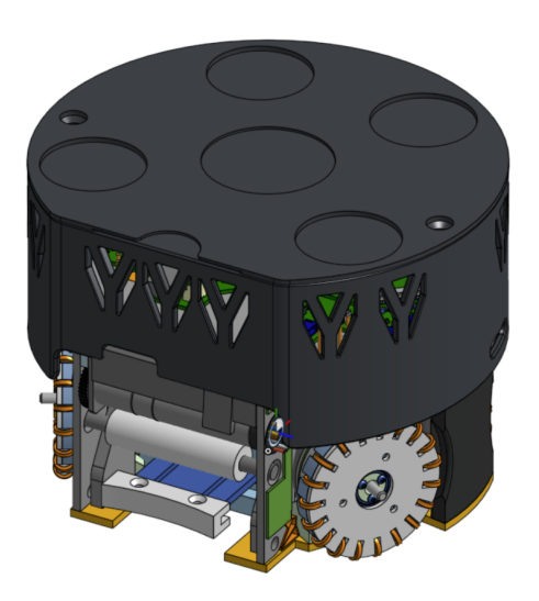
For 2024-2025, our mechanical team has focused on making improvements to our previous robot design, including major upgrades to the drivetrain and the dribbler. We have also been improving our robots' robustness and manufacturability by optimizing several component designs, as detailed in the following sections. Our most recent CAD model is shown below in Figure 1.
2.1 New CAD Software
This year, our team underwent a significant transition by moving from Solid-Works to OnShape, a cloud-native computer-aided design (CAD) software system. Given that a substantial portion of our robot assembly required modifications to accommodate our new electrical stackup, we decided that this year was an ideal opportunity to make this change. OnShape offers a free and userfriendly cloud-based platform where multiple people can collaborate on the same document in real time without the need to push changes such as with regular PDM systems. The software can be accessed from any device without requiring any downloading, making it convenient to modify parts on the go.
2.2 Drivetrain
This year, we moved away from our internal gear setup to a direct drive, offering us a compact design and better consistency. Our previous drivetrain setup was also prone to have the omniwheel rollers fall off, as the copper wire used to hold it together was difficult to keep in place.
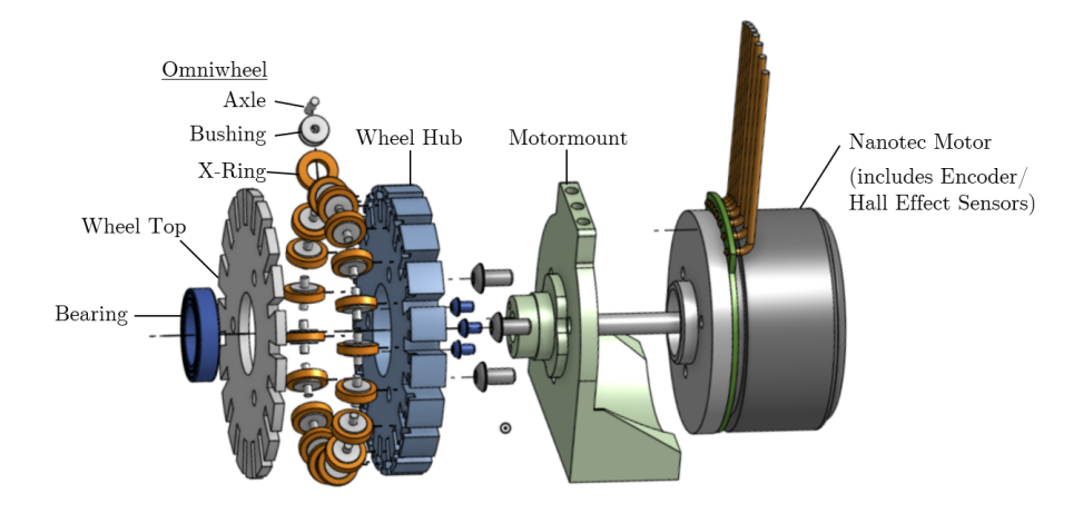
Omniwheels We decreased from 21 to 19 rollers in our new omniwheel design (Figure 2), with each roller consisting of a bushing, rubber X-ring, and a dowel pin. We opted to use X-rings over the traditional O-rings, due to their increased surface area and contact with the ground. These qualities mean that X-rings have improved traction and stability over O rings.
From our design 2020 onwards, the omniwheels were placed around a copper wire, which was then secured between the wheel cover and wheel base. While functional, this design made repair and disassembly very inefficient, as it required removal of the entire omniwheel system each time and the rollers would get displaced. This year, we replaced the copper wire with individual dowel pins for each omniwheel. With this change, we are able to isolate each omniwheel for easier removal and maintenance.
2.3 Dribbler Assembly
One of the bigger changes for our dribbler assembly is redesigning the sideplates to create space for the breakbeam PCBs, which will now be placed directly on the sides without the need for long wires that would often interfere with the fast-spinning dribbler motor. The new PCB schematics for the breakbeam have been discussed in Section 3.4.
Roller Our previous iterations of rollers were molded using polyurethane, the process for which required a lot of PPE, was prone to failure, and was incredibly time-consuming, which slowed down the speed of prototyping iterations of the design. Additionally, it was susceptible to tearing (especially the threads for centering) and required frequent replacements as the polyurethane hardens over time. To address this, we explored 3-D printing the rollers instead with TPU with a shore hardness of 60A. Although challenging to print, teams that have previously used this filament have seen success with its replicability and robustness compared to polyurethane molds. However, the threads previously used for centering were foregone in favor of a smooth cylindrical roller due to the filament's tendency to shred with the threads on and its difficulty in printing. Preliminary prototypes have shown promising results for the final product, but further adjustments to print settings are still needed for consistent results.
2.4 Solenoid Winding Machine
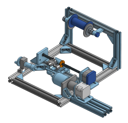
The previous iterations of chipper and kicker solenoids were produced by manual hand-winding of the magnetic coils. This led to inconsistent coil flux density which had to be corrected for with software calibration for each robot separately. In an effort to reduce this time consuming process and increase the uniformity between robots, this ongoing project aims to create a machine capable of producing custom solenoids. Previous attempts at building such a machine were unsuccessful due to difficulty applying adequate tension to the wire since the machine was largely made of 3-D printed components, which lacked the necessary rigidity. Our new design is made from 20x20 T/V Slot Aluminum extrusion. Figure 3 shows the CAD for our ongoing design. Two key features of this design are the coil tensioning system and the adjustable wire feeder. The tensioner works by tightening nuts on the spool holder bolt, squeezing the spool. The adjustable wire feeder can be moved in closer or farther from the solenoid to get very close to the solenoid during winding such that wire cannot drift from its intended location.
3 Electrical
(Section body follows)
3.1 Electrical System Overview
This year, the biggest project in our team was a complete overhaul of the electrical subsystem. Many issues were arising with our past motor drivers, and after observing our performance during RoboCup 2024, we decided that a redesign was necessary. Another massive change from RoboCup 2024 was shifting from the Jetson Nano to the Raspberry Pi 5 for our main processing unit, requiring further modifications to our boards. This year, we had to change almost all of our electrical systems to accommodate both of these reasons. In addition, we deprecated a lot of older systems that were not currently in use; these include the geneva drive, radio, and CPU heartbeat.
3.2 Power Board
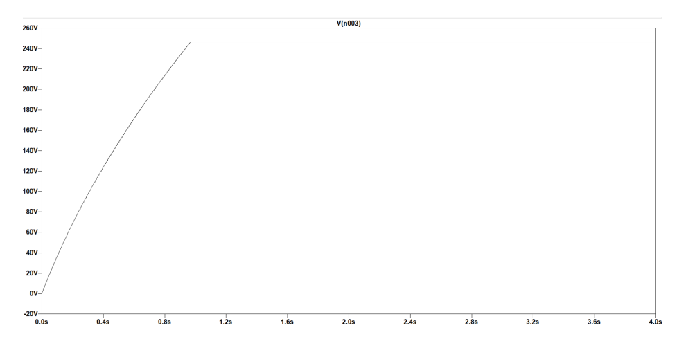
The flyback controller used the LT3751, which is now discontinued and caused problems with overheating in the last competition. Currently, the flyback is being redesigned with the LT3750. The LT3750 and the LT3757 were both modeled on LTSpice, and the LT3750 performed better, ramping to the necessary voltage faster and with a smaller transient. We continued to reiterate our design with the LT3750 and optimized it for performance and speed. Another major design change in our power boards was introducing isolation between the high-voltage and low-voltage components, in order to reduce interference from the high-current discharge circuits appearing in our low voltage signals; isolated gate drivers and an isolated 24V-12V DC-DC converter were used to achieve this isolation.
3.3 Motor Driver Board
The motor driver board is currently undergoing its two-year redesign cycle with the aim to modularize the hardware into five separate boards. The previous iteration of the motor driver board (MD V5) presented issues with price, solderability, debugging, and overall complexity. With the latest version (MD V6), each individual board will consist of its own power stage (inverter circuit), integrated magnetic encoder, and current sensing circuits.
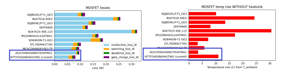
Power MOSFET Selection For MD V5, the NTTFD4D0N04HLTWG mosfet served as the power switch. Referring to Figure 5a, the mosfet possesses the lowest overall loss. However, it has a high temperature rise during switch mode operations, which incur power loss due to the positive thermal coefficient. In addition, it is expensive to purchase. As a result, we selected the Infineon OptiMOS-6 IAUC45N04S6 dual package power MOSFET to implement into the power stage of the next iteration of the motor driver boards. As shown in Figure 5a and Figure 5b, the OptiMOS-6 has a comparable conduction loss to the NT-TFD4D0N04HLTWG, but a lower temperature rise. This not only reduces power loss, but also mitigates the potential for thermal runaway. The OptiMOS-6 is four times cheaper compared to the NTTFD4D0N04HLTWG, which is ideal for a student design team. From Figure 5a, it can be observed that the OptiMOS-6 has less switching and gate charge loss. This is crucial because it entails significantly lower gate charge, which is a critical parameter in calculating the figure of merit of a power mosfet (FoM). The FoM is determined by the product of the $R_{DS-on}$ and $Q_g$, and it represents the efficiency of a power mosfet in high-speed switching applications.
$$FoMforOptiMOS=Q_g\cdot R_{DS-on}=9\cdot 5.6=50.4nC\cdot m\Omega$$
$$FoMforNTTFD4D0N04HLTWG=Q_g\cdot R_{DS-on}=18\cdot 4.5=81.0nC\cdot m\Omega$$
From the FoM calculations above, it can be seen that the FoM of the OptiMOS-6 is less than that of the NTTFD4D0N04HLTWG, which shows that the OptiMOS-6 would sustain less overall loss during operation. The OptiMOS-6 is the most optimal choice for a switch for the newest revision of the motor driver boards due being highly efficient and cheap.
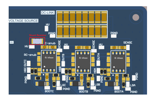
Current Sensing Circuit The layout complexity of MD V5 was substantially increased due to each phase of every power stage possessing its own shunt resistor for current sensing. To simplify the design, a single shunt resistor has been allocated per power stage in MD V6, as shown in Figure 6.
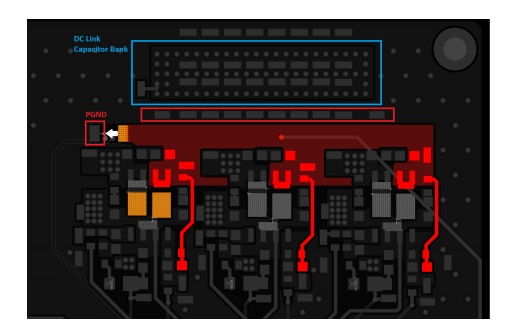
However, illustrated in Figure 7, it can be observed that there is a long return path for the current sensing signal for the half-bridge circuit furthest away from the shunt resistor back to power ground (PGND). Thus, creating a large hot loop between the power stage and DC link capacitor bank that induces a significant amount of ringing. To address this issue, we plan to implement shunt resistors for two of the three half-bridge circuits in the power stage. By doing so, this will minimize the area of the hot loop, thereby reducing ringing. The trade-off to this solution is that another differential op-amp circuit will need to be implemented to read the voltage drop across the second shunt resistor, which would increase area and complexity of the board.
3.4 Breakbeam Board
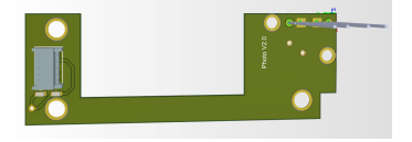
Breakbeam v2.0 We further enhanced our breakbeam design by removing one IR LED as we found that 2 IR LEDs were redundant. Due to them causing interference and accidentally triggering the breakbeam when the robot does not possess a ball. We also changed resistor values to 10MΩs for optimal sensitivity. We redesigned the board shape to connect the IR LED and Phototransistor PCB Boards to the main breakbeam board. This allows these longer PCBs to be attached to the side of the dribbler which provides a shorter connection distance and a more secure connection while also removing the need for wires running down the side of the dribbler.
3.5 IMU
The inertial measurement unit (IMU) takes measurements of the acceleration, angular velocity and orientation during gameplay, to allow for accurate data to be relayed to our software systems. This will be used in tandem with the camera data in order to accurately and effectively plan the motion of our robots. The IMU is located closer to the bottom of the robot's center of gravity to minimize the effect of rotational acceleration. This ensures that we have the most accurate representation of the robot's motion. We selected the LSM6DSL iNEMO Inertial Module as our permanent implementation. Regarding design specifics, we attached connectors and added test points to aid with future debugging.
3.6 Kick-speed Test Jig
We are developing a test jig to measure the speed of a kicked ball. This will allow us to measure the performance of the robot's kicker, allowing us to make improvements as we see fit. The test jig is in the shape of an arch and consists of 2 PCBs, mounted on its sides. The PCBs include an ESP32 microcontroller, IR emitters, and phototransistors. The ESP32 uses timers to save the times at which the first and second IR emitter beams are broken and calculates the speed using a set distance.
4 Software
All of our software and firmware is open source and available from our git repository: https://github.com/UBC-Thunderbots/Software.
4.1 Communication Latency
A key requirement for any RoboCup SSL team is low-latency communication between the high-level control software and the 11 robots on the field. This requirement is important because of the high speed of the robot in a constrained space. High latencies impact the robot's ability to follow its path and significantly increases the risk of collisions.
Since RoboCup 2022, we have used 5 GHz WiFi as its main communication medium. This choice offered significant advantages over 2.4 GHz radio communication, namely:
- An increase in the maximum payload size that could be carried in a single network transaction. Generally, the Maximum Transmission Unit is determined by the frame size of the Ethernet layer, which is typically 1500 bytes. In contrast, the NRF24L01 2.4 GHz radio transceiver—a popular choice in the league—supports a maximum payload of 24 bytes in a single transaction. The increased payload size allows for more communication and diagnostics from the robots.
- More maintainable and portable code. We can leverage the Linux socket API to create portable transport code that works on various computers and across both ethernet and WiFi networks, improving accessibility and reducing barriers for new members to work on robot testing.
- Less hardware maintenance. A 2.4 GHz radio solution necessitates a carefully designed radio board with appropriate grounding and power specifications as well as base station(s) for the host laptop. In addition, the ability to run robots in a testing environment is limited by the number of working base station modules and compatible USB-SPI drivers.
Despite these benefits, our team identified critical WiFi 5 GHz limitations during SSL games. These included:
- High packet latencies. The recorded packet round-trip times were as high as 100 ms in Robocup 2024.
- High packet loss. The packet loss recorded was as high as 20% in Robocup 2024.
- Network congestion in a venue environment. Due to the crowded venue and the presence of unrestricted WiFi hotspots, the crowded signal environment at RoboCup appears to lead to poorer WiFi performance.
This year, we have tested various factors that could impact WiFi latency to improve its reliability in games.
Test Setup The following tests present the results of a host computer directly connected over Ethernet to the router and a single robot with a Raspberry Pi 5 3 m away from the router connected via WiFi. The primary node running on the host computer synchronously sends 200 1000-byte payloads using UDP to the robot. Once the secondary node running on the robot receives the packet, it immediately sends it back to the primary node. Then, the primary node records the round trip time once it receives the response or restarts transmission in the event of a timeout. Both primary and secondary nodes are implemented in C++ through the boost::socket API.
Factors The team studied the following factors in overall WiFi performance:
- AC wall power compared to DC batteries
- The use of external WiFi cards instead of the onboard option.
- WiFi 5 and WiFi 6E GHz
- Multicast and unicast communication
Power The team did not observe significant differences in WiFi performance when the robot was powered through the AC wall adapter or DC batteries. We expected that the power demands of the Raspberry Pi 5 as well as other robot components would cause a degradation in the performance of the WiFi cards due to possible power instability when using DC batteries. Surprisingly, we encountered occasional performance degradation regardless of the power source; These degradations were marked by sporadic bursts of 100-ms round-trip times. The team strongly suspects that the Linux network power management behavior is at fault. On both Jetson Nano and Raspberry Pi 5 embedded hosts, disabling wifi.powersave seem to have eliminated these round-trip time spikes.
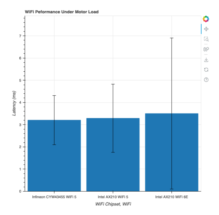
On-board WiFi and external WiFi Next, the team compared WiFi performance with the Infineon CYW43455 WiFi 5 card onboard and an Intel AX210 WiFi 6 card connected via the PCIe interconnect to a M.2 adapter HAT. The Infineon chip only supports 2.4 GHz and 5 GHz bands while the AX210 supports 2.4 GHz, 5 GHz and 6 GHz bands. As seen in Figure 9, the team was unable to find a statistically significant difference in performance between the onboard card and the external card.
WiFi 5 and WiFi 6E The main advantage offered by the Intel AX210 card over the onboard Infineon CYW43455 WiFi 5 is the expanded access to 6 GHz networks. In an evaluation of WiFi 6E in industrial contexts, Rong describes how the reliability of a multi-robot latency-sensitive application declines with the number of robots on the network. In simulations, Rong shows that WiFi 6E offers improved reliability for multi-robot scenarios, achieving 90% reliability for a system with 24 robots with a 20 ms traffic periodicity with WiFi 6E while only achieving the same reliability with 18 robots using WiFi 5. However, Figure 9 shows that in our test environment, performance on the 6 GHz network was similar to 5 GHz, but with a much larger performance variance. Nevertheless, the team's test environment does not simulate venue conditions well; The competition environment is densely populated with many devices contributing to WiFi congestion. In this environment, the relatively lower WiFi 6 adoption and larger 6 GHz spectrum available may be key for delivering low-latency communication. As such, the team plans on continuing to test both WiFi 5 and WiFi 6E in Robocup 2025 before making any conclusions.
Multicast and unicast Finally, the team considered the effect of networking architecture of latency. IP multicast is a one-to-many architecture that allows a single node to send a message to all nodes who have chosen to join that membership group. This architecture is an elegant solution to manage robots and computers on the network without needing to share IP addresses; On boot, robots join the multicast group on boot and will receive control messages. Meanwhile, interested computers will join the multicast group to receive diagnostics and error logs from the robots. In contrast, unicast is a one-to-one architecture where any two nodes directly communicate with each other using each other's IP addresses. This architecture requires both nodes to know each other's IP addresses.
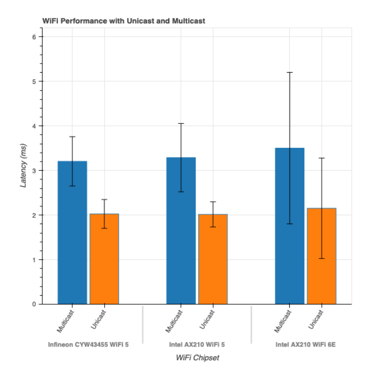
Since moving to WiFi communication, we have exclusively used multicast to communicate with robots. However, RFC 9119 advises against using multicast over WiFi. In essence, multicast over WiFi may be sent at a lower rate to maximize the likelihood of all nodes on the network receiving the packet while unicast may offer up to three orders of magnitude improvement over multicast/broadcast because the router can transmit at a higher transmission rate to capable receivers while technologies such as Multiple Input Multiple Output (MIMO) can be more effectively used.
In our tests, we have found that the WiFi architecture does make a significant difference reducing round-trip time latencies. On average, it resulted in a 24% improvement in round-trip times across the chipset and the WiFi 5/6E spectrum. As a result of this finding, we have adopted a unicast-based communication architecture for control messages and diagnostics logs with a low-rate, low-data multicast background rountine to facilitate automatic IP discovery between the robot and control node.
In Robocup 2025, we look forward to testing our efforts in low-latency WiFi communication.
4.2 Skill-Based Reinforcement Learning
For the past decade, our team has used the Skill, Tactics, Plays (STP) framework to implement our AI. Our rule-based STP system, while easy to understand and control, often struggles to adapt dynamically to the unpredictability of a fast-paced soccer environment. This year, we experimented with introducing reinforcement learning (RL) into our AI, with the aim to explore a wider variety of gameplay behaviours and enable our AI to intelligently react to a diverse range of scenarios.
Background Reinforcement learning is an area of machine learning concerned with teaching agents how they should optimally behave in a dynamic environment. Agents learn this optimal behaviour by interacting with the environment through trial and error and by receiving rewards as feedback.
We formalize the RL problem as a Markov decision process (MDP), which is defined by a tuple (S, A, P, R) with state space S, action space A, transition probability function P(s, a, s'), and reward function R(s, a, s'). At each time step t, the agent receives the current state $s_t \in S$ from the environment and responds by taking some action $a_t \in A$. The environment then transitions into a new state $s_{t+1} \in S$ with probability $P(s_t, a_t, s_{t+1})$ and awards an immediate reward $r_t$ given by $R(s_t, a_t, s_{t+1})$.
The agent selects actions following a policy $\pi(s)$ that defines a probability distribution on $\mathcal{A}$ for each state. The goal of the agent is to find an optimal policy $\pi^*$ which maximizes the expected return—the cumulative, discounted reward over all time steps—defined as $R = \sum_{t=0}^{\infty} \gamma^t r_t$ where $\gamma \in [0,1]$ is the discount factor.
Q-learning is a popular reinforcement learning algorithm used to learn the optimal policy $\pi^$ via a function Q(s, a) which estimates the expected return for taking action a in state s. The optimal $Q^$ satisfies the Bellman equation:
$$Q^(s_t, a_t) = \mathbb{E}{s{t+1}} \left[ r_t + \gamma \max_{a_{t+1}} Q^(s_{t+1}, a_{t+1}) \mid s_t, a_t \right]$$
To approximate $Q^*$, we train a deep neural network that takes input s and outputs $Q(s, a_1), ..., Q(s, a_{|\mathcal{A}|})$. The network is parameterized by $\theta$ and trained with the loss function:
$$L(\theta) = \mathbb{E}{(s_t, a_t, r_t, s{t+1})} \left[ \left( r_t + \gamma \max_{a_{t+1}} Q(s_{t+1}, a_{t+1}; \theta^-) - Q(s_t, a_t; \theta) \right)^2 \right]$$
where $\theta^-$ represents the parameters of a target network, which is updated less frequently to stabilize learning. This network is called a deep Q-network (DQN).
Setup In our AI, we designate the robot with possession of the ball as the attacker. The attacker agent can execute a set of rudimentary skills (e.g. pass, kick on goal, dribble away from enemies, etc.) and uses a DQN to select which skill to execute given the current game state. We implement skills using hand-crafted finite-state machines (FSMs) written with the Boost::ext.SML C++ library. A skill FSM instructs a robot how to move and execute the skill using rule-based and heuristic-based algorithms. The remaining robots on the team are controlled by existing Tactics implemented in our AI for offensive positioning and receiving passes.
We use PyTorch to implement our attacker DQN. We extend our DQN with prioritized experience replay to improve sampling efficiency. For the training environment, we use a modified version of ER Force's SSL Simulator with TIGERs AutoRef. We represent the state of the game as a 57-dimensional vector summarizing the ball position and velocity; coordinates, orientations, and velocities of all the robots; the current attacker robot; and the referee state (yellow cards, red cards, time remaining, etc.). We use a simple reward function that awards a +1 reward when a goal is scored, a -1 penalty when a goal is conceded, and a small positive reward that scales proportionally with the distance the ball travels towards the enemy goal, measured using the position of the ball before and after each skill is executed.
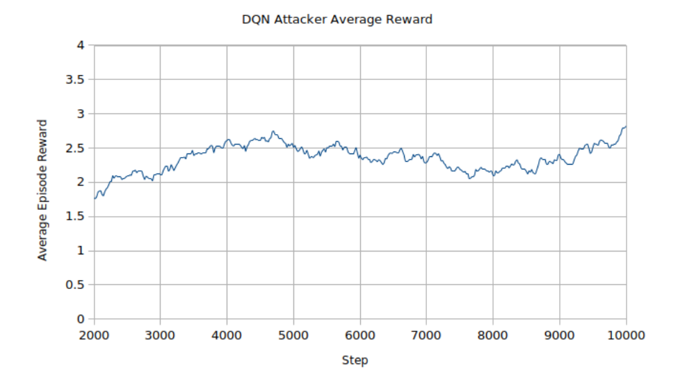
Experimental Results As a small-scale inquiry, we trained with self-play for 10,000 steps. The agent followed an $\epsilon$-greedy policy with $\epsilon$ annealing during training.
Our DQN attacker agent demonstrates promising results and some emergent strategic behaviour. As a benchmark, we played our DQN agent against our rule-based AI, and the DQN agent managed to consistently beat our rule-based AI across three repetitions of the experiment. We will continue to evaluate and improve the performance of our RL agent with more training time and enhancements to the DQN algorithm.
5 Conclusion
We believe that the design changes detailed above will lead to significant improvements in performance. We look forward to implementing these designs at RoboCup 2025.
6 Acknowledgements
We would like to thank our sponsors as well as the University of British Columbia, namely the Faculty of Applied Science and the departments of Math, Mechanical Engineering, Electrical and Computer Engineering, Integrated Engineering, Manufacturing Engineering, and Materials Engineering. Without their support, developing our robots and competing at RoboCup would not be possible.
References
- P. Dumitru, G. Ellis, J. Fink, B. Hers, J. Lew, M. MacDougall, E. Morcom, S. H., C. Sousa, W. Van Dam, G. Whyte, L. Zhang, S. Zheng, and Y. Zhou, "2020 Team Description Paper: UBC Thunderbots," 2020.
- A. Senthilkumar, A. Sidhu, A. Balamurali, D. Sturn, D. Antoniuk, D. To, F. Muhstaq, F. Crema, H. Bryant, H. Rovner, J. Lew, K. Wakaba, N. Zareian, O. Levy, R. Khan, R. Cao, R. Nedjabat, T. Kong, S. Ajmal, S. Ly, and Y. Zhou, "2023 Team Description Paper: UBC Thunderbots," 2023.
- N. Ommer, A. Ryll, M. Ratzel, and M. Geiger, "Extended Team Description for RoboCup 2024," 2024.
- A. Abousaleh, A. Balamurali, B. Blair, R. Cao, M. Charara, L. Chee, J. Coffin, J. Guo, W. Ha, F. Haas, T. Kong, R. Khan, C. Lee, O. Levy, R. Nedjabat, M. Phung, A. Sidhu, D. Sturn, M. Tong, B. Vasilchikov, K. Wakaba, N. Zareian, S. Banna, P. Zhou, and Y. Zhou, "2024 Team Description Paper: UBC Thunderbots," 2024.
- nRF24L01 Single Chip 2.4 GHz Transceiver Product Specification, 2007.
- W. Rong, Wi-Fi 6E Performance Evaluation in Industrial Scenarios. PhD thesis, KTH Royal Institute of Technology, 2021.
- C. E. Perkins, M. McBride, D. Stanley, W. A. Kumari, and J.-C. Zúñiga, "Multicast Considerations over IEEE 802 Wireless Media." RFC 9119, Oct. 2021.
- B. Browning, J. Bruce, and M. Veloso, "Stp: Skills, tactics, and plays for multi-robot control in adversarial environments," Proceedings of the Institution of Mechanical Engineers, Part I: Journal of Systems and Control Engineering, vol. 219, no. 1, p. 33–52, 2006.
- R. S. Sutton and A. G. Barto, Reinforcement Learning: An Introduction. The MIT Press, second ed., 2018.
- V. Mnih, K. Kavukcuoglu, D. Silver, A. Graves, I. Antonoglou, D. Wierstra, and M. Riedmiller, "Playing atari with deep reinforcement learning," 2013.
- K. Jusiak, "boost-ext/sml." https://github.com/boost-ext/sml, 2021.
- A. Almoallim, C. Sousa, D. Sturn, D. Antoniuk, F. Crema, H. Bryant, J. Lew, J. Liu, K. Wakaba, L. Bontkes, and Y. Zhou, "2022 Team Description Paper: UBC Thunderbots," 2022.
- J. Ansel, E. Yang, H. He, N. Gimelshein, A. Jain, M. Voznesensky, B. Bao, P. Bell, D. Berard, E. Burovski, G. Chauhan, A. Chourdia, W. Constable, A. Desmaison, Z. DeVito, E. Ellison, W. Feng, J. Gong, M. Gschwind, B. Hirsh, S. Huang, K. Kalambarkar, L. Kirsch, M. Lazos, M. Lezcano, Y. Liang, J. Liang, Y. Lu, C. Luk, B. Maher, Y. Pan, C. Puhrsch, M. Reso, M. Saroufim, M. Y. Siraichi, H. Suk, M. Suo, P. Tillet, E. Wang, X. Wang, W. Wen, S. Zhang, X. Zhao, K. Zhou, R. Zou, A. Mathews, G. Chanan, P. Wu, and S. Chintala, "PyTorch 2: Faster Machine Learning Through Dynamic Python Bytecode Transformation and Graph Compilation," in 29th ACM International Conference on Architectural Support for Programming Languages and Operating Systems, Volume 2 (ASPLOS '24), ACM, Apr. 2024.
- T. Schaul, J. Quan, I. Antonoglou, and D. Silver, "Prioritized experience replay," 2015.
- P. Bergmann, T. Engelhardt, T. Heineken, V. Hopf, M. Schmid, M. Schmidt, F. Schofer, K. Schuh, and M. Stadler, "Er-force 2022 extended team description paper," 2022.
- L. Magel, "Development of an autonomous referee software for the small size league," 2016.