Warthog Robotics SSL Team Description Paper for RoboCup 2025
Caio O. Godinho, João V. B. Benedetti, Antônio J. V. Miranda, Fábio R. A. F. Júnior, Alexandre M. I. Junior, Felipe V. de Oliveira, Pedro A. G. Pizarro, Rafael G. Lang, Ivan N. da Silva, Roseli A. F. Romero
University of São Paulo at São Carlos
Abstract This paper presents the Warthog Robotics Serpens project and the key improvements made to this RoboCup Soccer Small Size League initiative over the past year. The research and development cycle included various experiments with different navigation algorithms and implementing the Unscented Kalman Filter for filtering computer vision data. In addition, a new artificial intelligence approach based on Behavior Trees was introduced to improve decision-making. On the hardware side, several modifications were made to enhance the group's main robotic team, including improved power efficiency and upgrades from legacy hardware. These include the design and fabrication of new kick and station boards, the modification of the kicker actuator, and the upgrade of the connector board interface. Furthermore, a new lowcost hardware design, reducing per-robot costs to below USD 350, is also briefly explained, as it was used as a robot sandbox to develop new features.
1 Introduction
Warthog Robotics is a research and development Robotics group from the University of São Paulo at São Carlos. The group consists of over 100 members from several knowledge areas, such as Computer Science and Electrical, Mechatronics, and Computer Engineering, and develops Robotics technologies in various areas, applying most of them at Robotics competitions. Due to budget limitations, the team was unable to participate in the last edition of RoboCup but is still participating in local competitions, securing second place in 2023 Competição Brasileira de Robótica and fourth place in the 2024 edition.
Warthog Robotics' latest software improvements are detailed in Subsections 2.1 to 2.3. These enhancements primarily focus on new approaches to artificial intelligence (AI) and navigation algorithms. Besides that, an Unscented Kalman Filter was tested for computer vision data filtering and compared with the previous method of the team, as outlined in previous TDPs [17] [8]. Hardware improvements were also implemented to improve robustness and efficiency, as described in Sections 3.1 to 3.6. Following last year's TDP (Team Description Papers)[8], a new PCB (Printed Circuit Board) for radio communication with the robots was developed and is detailed in section 3.3. Furthermore, a competitive low-cost RoboCup Soccer Small Size League (SSL) project was designed and is discussed in Section 4.
2 Software Improvements
The software improvements described in Sections 2.1, 2.2, and 2.3 were first implemented and validated using the low-cost SSL robot presented in Section 4, focusing primarily on developing experimental ideas that were not mature enough to be incorporated into the team's main software package. This system was able to compete in the Competição Brasileira de Robótica previously mentioned, and, after further analyses, some snippets and features will make it to the primary software suite.
2.1 Behavior Tree
A new AI module that makes extensive use of Behavior Trees (BTs) has been developed in the decision-making process of the robotic system. This Section discusses some of the motivations that guided the choice of BTs over the previous Finite State Machines (FSMs) approach.
FSMs are very useful graph structures that can effectively abstract intricate logic and behavior, while still being intuitive and simple when applied to systems that tend to have a limited number of states and state transitions. Even so, when given a task where states and state transitions are numerous, e.g. a multi-agent complex system such as robot football, FSMs can get very complex, unreliable, unresponsive, and difficult to understand by the development team [11].
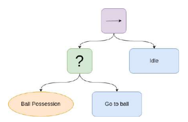
As the name suggests, BTs are a tree-derived construct that abstracts behavior by the usage of internal nodes known as control flow nodes and leaf nodes known as execution nodes. The primary types of control flow nodes are sequences (denoted by the symbol "->") and fallbacks (denoted by the symbol "?") and execution nodes can be either conditions or actions. Each node will have a function named tick() that returns a status that can be one of: SUCCESS, FAILURE, or RUNNING [4].
A sequence node will return SUCCESS if and only if all of its child nodes return a SUCCESS status, while a fallback node will return SUCCESS if any of its children return SUCCESS. Condition nodes return FAILURE when they are evaluated as false and SUCCESS when they are evaluated as true. At last, action nodes require the programmer to choose a heuristic to be used to return the appropriate status.
To build a Behavior Tree, the programmer uses a combination of the discussed node types by assigning child nodes and parent nodes in a given order. This hierarchical arrangement allows for modular and reusable behavior definitions. The root node initiates the process, "ticking" its children nodes in the defined sequence or fallback order.
Overall, Behavior Trees are generally less intuitive than Finite State Machines, but they end up offering a lot of modularity, less code repetition, and more flexibility when scripting new behaviors for the robotic system. Another great advantage is that there is no need to worry too much about invalid states, as BT is capable of providing safer code through the usage of fallback nodes. Moreover, as explained in [4], the BT can be seen as a generalization of previous ideas in behavioral planning, and thus it could be extended in the future to support a more robust approach called Planning and Acting (PA-BT), where a plan is built online to reach a certain goal instead of purely reactive actions.
2.2 Motion Planning
Inside the field of motion-planning, different alternatives were tried to improve our existing approach. The previous implementation used a potential fields algorithm as a path planner followed by a high-level PID controller. The path planner determined the direction of the linear velocity vector of the robot, while the PID controller calculated its magnitude.
First, a few different path-planning algorithms were explored to check if there could be a better solution to our current configuration. Our goal was to find an algorithm that was able to output a shorter path in a reasonable time frame, and, if possible, to avoid purely reactive algorithms such as the potential fields. As described in [13], path-planning algorithms can be categorized as combinatorial or sampling-based. To evaluate both types, the Visibility Graph [2] and Informed RRT* [7] were selected.
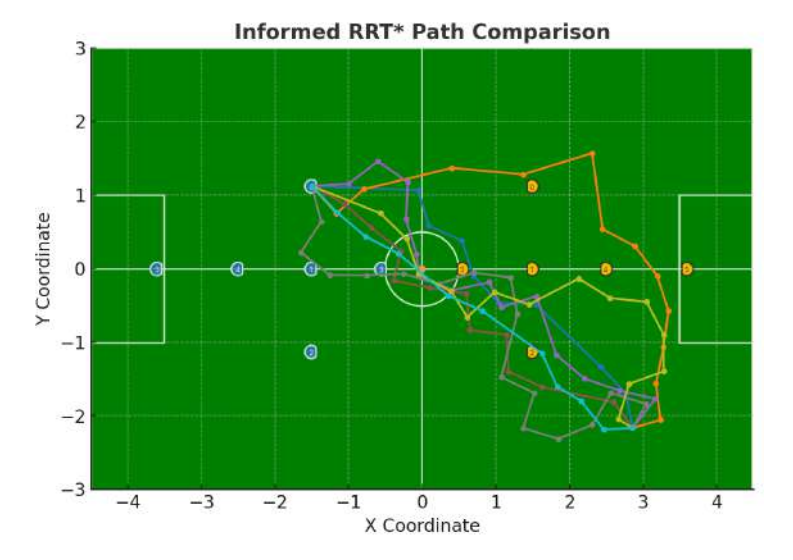
The Informed RRT* is a sampling-based path-planning algorithm that belongs to the family of RRT-based heuristics. The Informed RRT* tries to leverage sampling from inside an ellipsoid that encapsulates both, start and goal regions, to find the best possible path. An example of these generated paths is presented in Figure 2. This proved to be a computationally intensive algorithm, hindering its ability to perform in an environment such as the RoboCup SSL competition. Another issue found is that the number of iterations for the algorithm had to be reduced to be able to run inside the time frame of 16 ms, which is the upper bound for the system. The reduction ended up making the calculated paths too inefficient and they weren't smooth enough, raising the need to run a postprocessing algorithm such as a Bézier curve [18] or a more analytical solution such as quintic polynomials interpolation [3].
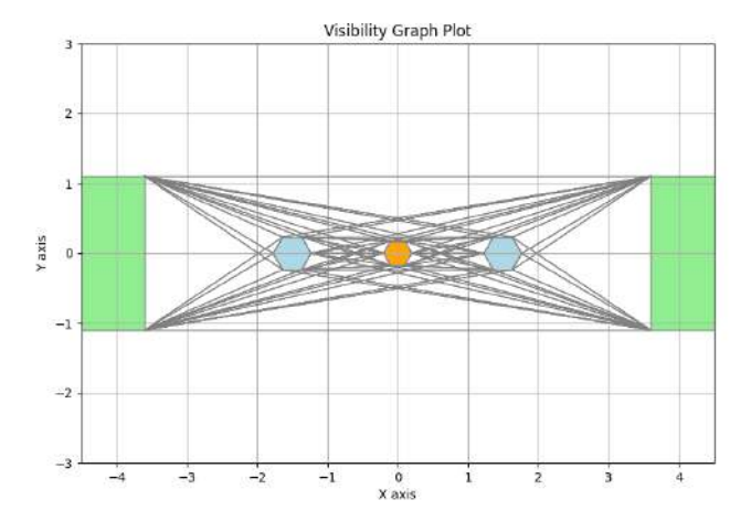
The Visibility Graph is a combinatorial algorithm that is best suited for twodimensional geometric problems, such as the SSL field. The approach consists of treating each object in the field as a polygon. For each of its vertices, the visibility towards every other vertex is calculated and an edge is added between them if they are visible to each other. The result, as shown in Figure 3, is a graph that can be queried for each robot using an algorithm such as Dijkstra's to find the shortest Euclidean path between a given goal and origin. The original algorithm, described in [2], runs in O(n² log n). This is computationally expensive for a large number of vertexes, but the visibility check procedure for each vertex can be easily multi-threaded, making the algorithm able to run in a reasonable time frame (inside 16 ms). So, this proved to be a viable choice and a path-planning algorithm.
On top of that, the team also tried to plan the whole trajectory for the robot. The goal was to evaluate whether the use of a high-level PID controller that frequently had to be re-tuned could be avoided. This was done using the approach described in Chapter 4.4.1 of [3], in which the waypoints that the robot should follow are used together with the initial and final velocities as input of a linear system that is solved to build a polynomial equation that can be scaled through time to obtain the necessary velocities for each time step. The algorithm was implemented and Figure 4 shows the velocity and acceleration responses. This approach proved to be very inefficient, as it was hard to determine velocities that were fast enough while not deviating too much from the calculated path. Also, because a linear system was to be solved, even tiny changes in the predicted path were detrimental when replanning was needed. This ended up justifying the usage of the PID controller that had previously been implemented.
![Using the Cubic Spline trajectory algorithm from [3] the following graphs are obtained: graph 1 shows the geometric path of a point-to-point trajectory, graph 2 shows the magnitude of the robot's velocity through time, and graph 3 shows the magnitude of the robot's acceleration through time.](/tdps/soccer_smallsize__2025__Warthog_Robotics/_page_5_Figure_2.jpeg)
Based on these analyses, the final choice for the motion planning setup was the adoption of the visibility graph as a path planner to find a valid collision-free geometric path and the PD controller to determine how fast the robot should move.
2.3 Unscented Kalman Filter
The Unscented Kalman Filter (UKF) is a Bayesian Filter well suited for systems with a high degree of nonlinearity and is often found in the literature as an alternative to the Extended Kalman Filter (EKF) and the regular Kalman Filter (KF) [25] [26]. The goal of their application lies in the possibility of correcting noisy data through a stochastic process consisting in trying to predict future measurements according to a theoretical model and updating the current system state using incoming data from one or more sensors.
As in the current state of the SSL category, robots have both translational and rotational velocities, which end up composing a nonlinear system, making it sensible to apply either an EKF or a UKF. Moreover, the UKF was explored because it is relatively less used by the league than the EKF, this could be attributed to the fact that the Jacobians of the system are easily computable, making the EKF easier to implement.
In contrast, the UKF relies on the unscented transform, which "is a method for calculating the statistics of a random variable which undergoes a nonlinear transformation" [26]. Therefore, this filter is more useful when the system is less predictable and does not have Jacobians that are conveniently calculated, and, as mentioned before, this is not the case in the SSL. Another consideration to be made is that the UKF was relatively slower than the previous Kalman Filter implementation [17], especially when applying the filter to a multi-camera system. Also, as the literature suggests for simpler systems, such as this, the final result of the UKF implementation was not that different from the previous KF, contributing to the decision to continue using what the team had before.
3 Hardware Improvements
All the following hardware improvements are related to the Warthog Robotics legacy robot, that is, not the low-cost robot described in Section 4.
3.1 BuckBoard
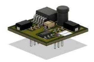
The BuckBoard is a power module designed to replace the linear voltage regulators on the MainBoard and to optimize energy efficiency and thermal management. This efficiency is given by the ratio between the output and input powers of the power supply circuit, establishing a relationship that indicates how much power is used effectively by the board. The goal of the BuckBoard is to make this ratio as close to the ideal as possible by combining a low-dropout (LDO) linear regulator and a buck converter (step-down regulator).
The BuckBoard, shown in Figure 5, solves this problem by integrating an LM2576HVS-5.0 buck converter integrated circuit. For this application, the efficiency is around 80% according to [24] and the established supply parameters. To stabilize the output and ensure low ripple, a LDO regulator from Texas Instruments, LM1117IMPX-3.3 [23], is used after the buck converter.
As a result, the power dissipation of the MainBoard has decreased from 2.2 W to 1.6 W, demonstrating a significant improvement in efficiency. Furthermore, the reduction in power dissipation improves better battery performance, saving around 9 minutes in standby mode.
3.2 KickBoard
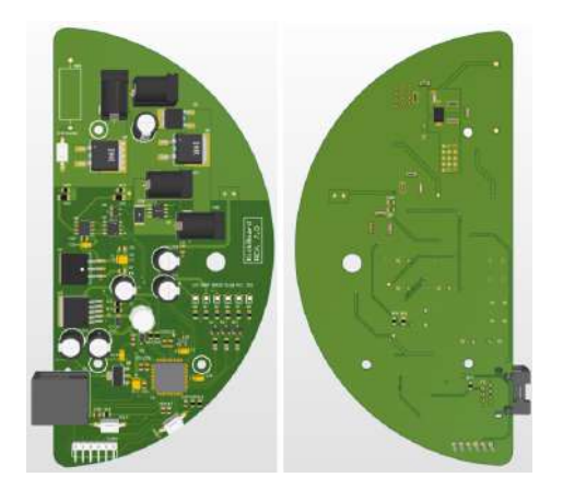
The KickBoard controls the entire kicking process, from raising the voltage using a boost circuit to activating the solenoid that actually hits the ball. Information about the other boards that make up the robot can be found in previous TDPs [12].
The KickBoard was the last standing manually-manufactured board in the robot. This was causing spurious errors that affected the board's functionality, such as the capacitor charging circuit suddenly stopping to work in the midst of a game. Furthermore, the old KickBoard design presented several errors due to the poor dimensioning of the power traces, which broke and suffered from noise generated by the charging circuit during games and tests.
With that in mind, to improve the stability and reliability aspects of the electronic project, a re-layout of the KickBoard was carried out, resizing traces, vias, and copper planes, increasing the width of the power tracks, and separating the GND (Ground) plane of digital signals from the power signals, coupling them at the point of lowest noise. In that way, the manufacturing process, unlike the previous version, was done industrially and new components for the boost circuit were chosen [1].
One of the main changes was the model of transistors present in the boost circuit and in the kick drive. The chosen model was Infineon's IRFS4229PbF [10], which has a breakdown voltage value (VDS) of 250 V, a maximum continuous drain current (ID) of 45 A, and RDS(on) of 42 mΩ. It is an SMD (Surface Mounted Device) model, more compact and modern compared to IRFP90N20DPbF [9], the model used in the previous version of the board. Another change was the addition of a circuit for current monitoring, that, together with the dsPIC33FJ128MC804 microcontroller [14], was responsible for controlling the capacitor charging time, using a shunt resistor [1].
3.3 Radio Station Board
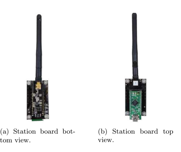
A new PCB was developed using the UM232H FTDI module to interface the USB (Universal Serial Bus) port of the computer and the nRF24L01+ radio module used in the communication between the computer and the robots. Figures 7a and 7b show the developed board. The internal IC (Integrated Circuit) of UM232H, FT232H, is used with the Multi-Protocol Synchronous Serial Engine (MPSSE), which offers flexible means of connecting synchronous serial devices to a USB 2.0 Hi-Speed (480 Mbits/s) port [6] [5]. The previous PCB used was hand-made and used a dsPIC to communicate with the radio module. This solution also offered good performance but was harder to program and debug, because the communication firmware had to be programmed in the dsPIC.
The MPSSE interface used by the FTDI modules allows the user to control and configure the embedded device through a personal computer's USB port. Furthermore, the maximum SPI clock frequency of the FT232H IC is 30 MHz, much higher than the maximum frequency for the nRF24L01+ of 10 MHz.
3.4 New Batteries
Another improvement made this year was the battery replacement, as the previous batteries had swollen and their effective lifespan had decreased significantly. In this new scenario, we now use a three-cell Lithium-Polymer (LiPo) battery with a capacity of just over 5000 mAh, much more than the current electrical system needs. With this change, robots can play several games without the need for charging. As the new batteries were the same size as the old ones, there was no need for mechanical changes in the robot.
Swollen LiPo batteries are not only inefficient but also dangerous to use. Therefore, experts recommend some common practices to decrease the rate of swelling of the batteries [27] [20]. Considering this, good habits for extending battery lifespan were adopted after realizing that the previous batteries had aged faster than expected due to a lack of preventive measures.
3.5 Micro-Fit Connectors
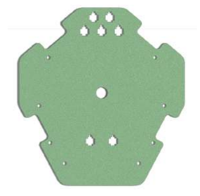
The current mechanical structure of the project is built in a modular way, especially when it comes to wiring. The cables for the devices on the robot's first floor, such as motors, kick solenoids, and ball sensors, have a male jack J4 panel connector at their terminals, without a mechanical lock. These connectors are fixed using a spring washer and a nut on the second floor of the robot, where the battery and kick capacitor are located. However, during games and tests with rapid movements and collisions, the robots often presented problems with poor contact in the wire connections, especially with the motor wires.
The solution found to minimize the problem was to replace the J4 panel connectors on the second floor with locking connectors, capable of withstanding the same electrical conditions as the old ones. The chosen model was the Micro-Fit 3.0 Plug Housing, Dual Row, 2 Circuits, which has a 3 mm pitch and supports up to 10.5 A of current.
In this context, the change of the panel connectors motivated a mechanical redesign of the robot's second floor (Battery Base), capable of physically supporting the new model. In addition, there was a change in the material of the new base, which was previously manufactured with fiberglass, and will now be composed of ABS 3D printing filament, which lowered the cost of its manufacture.
3.6 New Kick Actuators
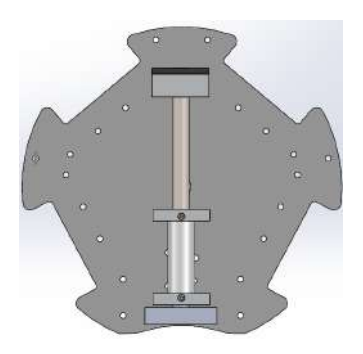
The old solenoid used in the kicking system has been replaced with a new one from Soletec (MPN 557.025.881 12 VCC) [21], which is more compact. Due to its smaller size, additional space on the base has been made for future projects, allowing for greater flexibility in design and additional component integration. Although much smaller, the new solenoid can still provide enough power for high-speed kicks (5-6 m/s) during a match.
4 Low-cost SSL Robot
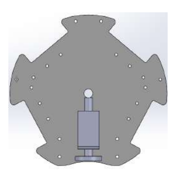
This section briefly describes the low-cost robot developed by Warthog Robotics, also known as the group's B team. The full detailed description of the robot and its hardware and firmware open source releases are under development and will be submitted to the 28th RoboCup International Symposium 2025 under the Robot Hardware and Software topic. This project was designed to achieve a low-cost but still competitive robot for SSL division B. Furthermore, it was used as a group sandbox to validate new hardware and software ideas, for instance: the usage of the RP2040 microcontroller in an SSL robot, a new artificial intelligence, a robot without an embedded motor closed-loop controller, and a fully 3D-printed robot (except for the sub-wheels of the omnidirectional wheels, which are made of aluminum).
Therefore, this project may potentially help new teams with a low budget join the league, allowing them to surpass the challenge of making their first SSL hardware and focusing on software development. One Warthog B robot is approximately valued at R$ 2,000.00 (two thousand Brazilian Reais).
A team of five robots competed in the 2024 RoboCup Brazilian Open Competition, placing fifth against eight other teams, including the other Warthog Robotics main team (A team). The primary challenge encountered was the frequent breaking of o-rings from the wheels, which impacted movement performance. Despite this, the fully 3D-printed hardware successfully endured all matches. A notable game against the RoboIME team is showcased in [22], where Warthog B competes as the yellow team.
This new robot is completely interchangeable with the current robots of the group, meaning that the final robotic system can be heterogeneous, allowing a team match to be played with robots from the Warthog Robotics' A and B teams together.
4.1 Robot Mechanics
The robot uses three wheels, each driven by a direct current (DC) motor from Microred, model A2-102-S [15], and controlled in a open loop (without an encoder) with just a K proportional gain. The entire system is powered by a three-cell LiPo battery (11.1 V) with a capacity of 5200 mAh.
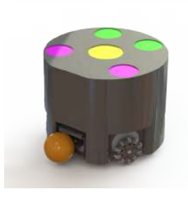
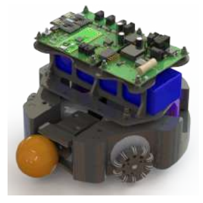
The structure is designed to accommodate three motors, the electronic board, bearings, battery, kicking device, and three omnidirectional wheels. The external cover is 3D printed in black ABS and is held in place with magnets, allowing quick access to the robot's internal hardware when needed. The internal layout consists of three main layers, from bottom to top: locomotion and kicker, battery, and PCBs.
Furthermore, most of the mechanical structure is 3D printed using Fused Deposition Modeling (FDM) with ABS. An exception is the wheels, which are manufactured using Selective Laser Sintering (SLS) with Nylon 12, while the sub-wheels for the omnidirectional wheels are machined from aluminum.
4.2 Robot Electronics
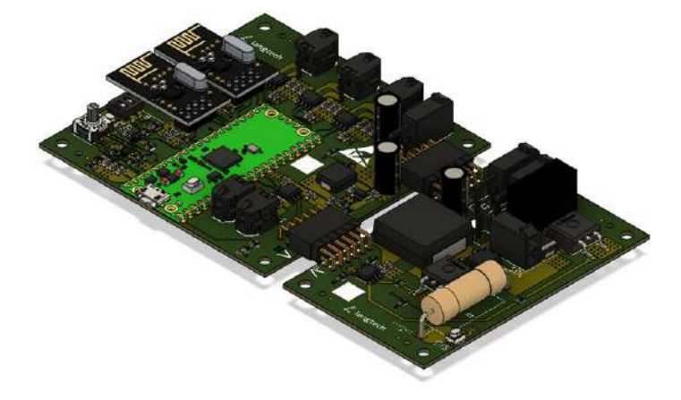
The electrical system consists of 2 PCBs: one for communication and motor-drive control (MainBoard) and another for kicking control (KickBoard). Radiofrequency communication is carried out with the nRF24L01+ transceiver [16]. The central processing unit used is the Raspberry Pi Pico module, an RP2040-based microcontroller board [19].
Warthog Robotics' A team uses two separate PCBs for the communication and motor control modules, enabling modularity and scalability by allowing individual module replacement without affecting the others. However, this approach increases both monetary costs and space requirements within the robot. Consequently, for this project, the communication (also called MainBoard) and motor control (also called MotorBoard) modules were integrated into a single PCB.
MainBoard The MainBoard of Warthog Robotics' B team receives the group's WRMagic protocol command data via the nRF24L01+, enabling its interchangeability with the other existing robots as previously mentioned. The radio information is sent via SPI to the RP2040 microcontroller embedded in the Raspberry Pi Pico module that processes it and: sends it to the DRV8231DDAR H-bridge, which amplifies the PWM (Pulse Width Modulation) control signals for the adequate operation of the A2-102-S DC motors; sends the kicking PWM to the KickBoard. Furthermore, other communication independent features are also processed by the RP2040, such as battery voltage monitoring, to generate a visual alarm via discrete LEDs when the battery is low, and the kicking capacitor voltage control.
The latter is managed by two PWM signals that are sent to the KickBoard using a board-to-board connector. One is used in a discrete boost circuit that charges the capacitors, increasing their voltage to 180 V. The other one is the kicking PWM, which is activated when two events occurs simultaneously: the ball sensor—comprising an infrared emitter and receiver—detects an interruption in its signal, indicating the presence of the ball; and a kicking command is received via radio.
KickBoard Unlike Warthog Robotics's A team KickBoard, the B team does not have its own microcontroller; as said before, the necessary PWM signals for the kicking system are generated by the Raspberry Pi Pico module in the MainBoard. The topology of the voltage converter circuit is the same as that used by the A team, a discrete boost converter, with minor differences. For instance, the inductor present in this new boost circuit is as an SMD model, instead of a hand-made one used in the previous KickBoard. This ensures better inductance accuracy and lower Equivalent Series Resistance (ESR) value. In addition, other components were changed, such as external capacitors and solenoid actuator connectors, changing from the J4 header connector to the Mini-Fit header model.
5 Conclusions and Future Work
Warthog Robotics's latest software improvements consisted primarily in different approaches for the AI and navigation algorithms. The Unscented Kalman algorithm was tested but didn't prove to be efficient in the SSL environment. Furthermore, improvements in the hardware ware made to increase the robot's energy consumption efficiency, eliminate poor contact in electrical connections, decrease space usage in the robot's base, buy new batteries, and make a new radio communication board.
In addition, a cost-effective SSL project was developed as a platform to validate the previously presented software concepts and features, as well as to assess manufacturing processes such as 3D printing and hardware components like the RP2040 microcontroller.
For future improvements in the Behavior Tree algorithm, it would be sensible to research and possibly develop a Reinforcement Learning approach to utility fallback nodes, in which the agent of the model would learn to best choose a certain branch of the Behavior Tree given the current game state.
Finally, a new hardware system is currently being developed, pursuing a higher level of quality and competitiveness, aiming to integrate the knowledge gained from the low-cost robot with the legacy robot still in use. New features such as chip-kick and ball roller shall be integrated into the project, and more efficient PCBs in terms of power consumption, communication speed, and space usage are currently in the design process.
References
- Andrade, L.T.C., da Silva, I.N.: Design e implementação do circuito boost da placa kickboard do grupo warthog robotics (2024)
- de Berg, M., Cheong, O., van Kreveld, M., Overmars, M.: Computational Geometry: Algorithms and Applications. Springer, Berlin, Germany, 3rd edn. (2008)
- Biagiotti, L., Melchiorri, C.: Trajectory Planning for Automatic Machines and Robots. Springer, Berlin, Germany (2008)
- Colledanchise, M., Ogren, P.: Behavior trees in robotics and AI: An introduction. CRC Press, an imprint of the Taylor Francis Group, an Informa business (2020)
- Future Technology Devices International: Application note an_135 ftdi mpsse basics, https://www.ftdichip.com/Documents/AppNotes/AN_135_MPSSE_Basics.pdf, last accessed 2025-02-01
- Future Technology Devices International: Um232h single channel usb hi-speed ft232h development module datasheet, https://ftdichip.com/wp-content/uploads/2020/07/DS_UM232H.pdf, last accessed 2025-02-01
- Gammell, D., Srinivasa, S.S., Barfoot, T.D.: Informed rrt*: Optimal sampling-based path planning focused via direct sampling of an admissible ellipsoidal heuristic. In: Proc. IEEE/RSJ Int. Conf. Intell. Robots Syst. (IROS). Chicago, IL, USA (2014)
- Godinho, C.O., Neumann, E.F., Françoso, P.A.P.: Description of the 2024 warthog robotics ssl project (2024)
- International Rectifier: Irfp90n20dpbf - hexfet® power mosfet, https://www.infineon.com/dgdl/irfp90n20dpbf.pdf?fileId=5546d462533600a40153562ccb60202f, last accessed 2025-02-10
- International Rectifier: Irfs4229pbf - hexfet® power mosfet, https://www.infineon.com/dgdl/irfs4229pbf.pdf?fileId=5546d462533600a401535639fdc421a1, last accessed 2025-02-10
- Iovino, M., Förster, J., Falco, P., Chung, J.J., Siegwart, R., Smith, C.: Comparison between behavior trees and finite state machines. arXiv preprint arXiv:2405.16137 (2024), https://arxiv.org/abs/2405.16137, last accessed 2025-02-09
- Lang, R.G., Bernardo, A.M., de Oliveira, G.C., Menezes, H.B.B., Ramos, L.C., Roque, L.G.S., da Silva, I.N., Romero, R.A.F.: Description of the warthog robotics ssl 2015 project (2015)
- LaValle, S.M.: Planning Algorithms. Cambridge Univ. Press, Cambridge, U.K. (2006), http://planning.cs.uiuc.edu/
- Microchip: dspic33fj128mc804 - 16-bit digital signal controller, https://ww1.microchip.com/downloads/en/DeviceDoc/70000107G.pdf, last accessed 2025-02-10
- MICRORED: Microredutor modelo a- 12vdc 5,4w (102-sj-v) e 8,4w (102-s), https://microred.com.br/CATALOGO-MODA-12V.pdf, last accessed 2025-02-10
- Nordic Semiconductor: Nrf24l01+ single chip 2.4ghz transceiver, https://cdn.sparkfun.com/assets/3/d/8/5/1/nRF24L01P_Product_Specification_1_0.pdf, last accessed 2025-02-10
- Pizarro, P.A.G., Granela, L.F., Andrade, L.T.C., Sakiyama, K.M., Lang, R.G., da Silva, I.N., Romero, R.A.F.: Description of the 2023 warthog robotics ssl project (2023)
- Pomax: A primer on bézier curves, https://pomax.github.io/bezierinfo/, last accessed 2025-02-04
- Raspberry Pi Ltd: Raspberry pi pico datasheet, https://datasheets.raspberrypi.com/pico/pico-datasheet.pdf, last accessed 2025-02-10
- Schneider, B.: A guide to understanding lipo batteries, https://www.rogershobbycenter.com/lipoguide, last accessed 2025-02-09
- SOLETEC: Miniature solenoid - series - c, https://www.soletec.com.br/2015/02/solenoide-miniatura-serie-c.html, last accessed 2025-02-09
- SPbUnited: Warthog b - roboime | group 1 | robótica 2024, https://youtu.be/r7OXYQSgay8, last accessed 2025-02-02
- Texas Instruments: Lm1117 low dropout voltage regulator, https://www.ti.com/lit/ds/symlink/lm1117.pdf, last accessed 2025-02-10
- Texas Instruments: Lm2576xx series simple switcher® power converter 3-a stepdown voltage regulator, https://www.ti.com/lit/ds/symlink/lm2576.pdf, last accessed 2025-02-10
- Thrun, S., Burgard, W., Fox, D.: Probabilistic Robotics. MIT Press, Cambridge, MA (2005)
- Wan, E.A., Merwe, R.V.D.: The unscented kalman filter for nonlinear estimation. In: Proceedings of the IEEE 2000 Adaptive Systems for Signal Processing, Communications, and Control Symposium (Cat. No.00EX373). pp. 153–158 (2000). https://doi.org/10.1109/ASSPCC.2000.882463
- Zhang, S.S.: Insight into the gassing problem of li-ion battery, https://doi.org/10.3389/fenrg.2014.00059, last accessed 2025-09-02