LUHbots RoboCup@Work 2019 Team Description Paper
Leonard Eberding, Salem Guezguez, Maximilian Hachen, Niklas Hahn, Oliver Uphus, Simon Lebbing, Daniel Wittwer, Marc Warnecke, Daniel Kaczor
LUHbots, Leibniz Universität Hannover Mechatronik Zentrum Hannover Appelstraße 11, 30167 Hanover, Germany; Hannover Centre for Mechatronics, Leibniz Universität Hannover; Institute of Mechatronic Systems, Leibniz Universität Hannover
Abstract In this paper we provide a description of the LUHbots team of the Leibniz University Hanover. We describe the current state of the team as well as current plans and research goals towards the 2019 RoboCup@Work tournament in Sydney, Australia. The software is based upon a ROS-architecture and the hardware uses a KUKA youBot as a basis. The focus of the team lies with failure tolerant approaches to autonomous mobile robotics.
1 Introduction
The LUHbots team was founded in 2012 at the Institute of Mechatronic Systems Leibniz Universität Hannover, consists of bachelor and master students. Most of the founding team members have participated in the research inspired practical lecture RobotChallenge [9]. Nowadays the team is a part of the Hannover Centre for Mechatronics. The team consists of students from mechanical engineering, computer science, engineering and business administration and navigation and fieldrobotics. In 2012 the LUHbots team first competed in the RoboCup@Work challenge and was able to win the competition [8], in 2013 a second place was achieved [2]. In 2015 the LUHbots won both events, the German Open and the RoboCup in Hefei. In 2016 the team successfully completed the RoboCup@Work challenge in Leipzig (Germany), again achieving the first place.
2 Hardware
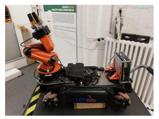
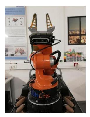
Our robot is based on the mobile robot KUKA youBot (see Fig. 1) [3]. The robot consists of a platform with four meccanum wheels [6] and a five degrees of freedom (DoF) manipulator. Additional a gripper is attached at the end of the manipulator (see Fig. 1). The internal computer of the youBot has been replaced by an Intel Core i7 based system. Furthermore we added a Nvidia Jetson TX2 board to run our computer vision. In addition, the robot is equipped with an emergency stop system, allowing for keeping the platform and the manipulator in the current pose when activated. The manipulator has been remounted to increase the manipulation area. The hardware itself does not offer failure tolerance, this is only achieved in combination with software.

2.1 Sensors
The youBot is equipped with two commercial laser range finders (Hokuyo URG-04LX-UG01) at the platform's front and back. A RGB-D camera (Intel RealSense D435) mounted on the wrist of the manipulator (see Fig. 1a) is used for object detection and classification.
2.2 Gripper
One of the major hardware advances performed by the team is the development of a custom gripper. The original gripper has a low speed and stroke. As a result, it is not possible, to grasp all objects defined by the RoboCup@Work rule book, without manually changing the gripper-fingers. Besides the limited stroke, the low speed limit does not allow for an appropriate grasping of moving objects. An advancement was to include force feedback into the gripper. Thanks to the integrated feedback within our custom made gripper, we are able to verify performed grasps. If a failure occurs during grasping, we are able to recover.
3 Approach
We take advantage of an open source software framework called Robot Operating System (ROS) [11]. We are using the Kinetic release. In our opinion dependability is one of the most important aspects of mobile robots, therefore we are constantly improving our testing procedures.
3.1 Overview
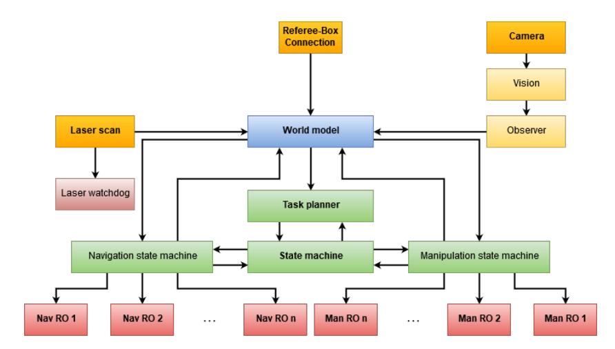
Due to the ROS based architecture, our system is based on different nodes communicating with each other using ROSTCP. For design and better insight for software developers nodelets are additionally implemented in the state machine. This way a hierarchical system can be implemented reaching from the Refereebox Connection to rudimentary operations (RO). RO's are defined as single actions independent of external factors. They are implemented using ROS action servers enabling the robot to receive updates of current tasks and cancelling them if necessary. Together they compose all navigation and manipulation actions. Also the software has been upgraded to a "Sense-Model-Think-Act" system. This means, that the data of all sensors are primarily accepted and directly used in the "Model" node. The "Think" software (mainly state machine and task planner) then use this stored information to make decisions and give this decision to the "Act" system, which is composed of different RO's. This architecture enables the robot to store and learn from data generated during the tests.
3.2 Manipulation
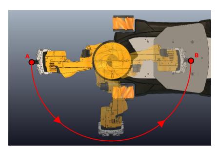
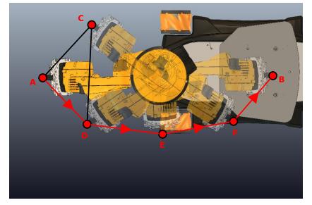
During the last years we developed a new software system that can be seen as a software development kit (SDK) for manipulation tasks with the youBot. The aim was to facilitate the development of applications for the youBot by providing advanced functionality for the manipulator and the mobile platform combined with user friendly interfaces. Some of the features for the manipulator are: inverse kinematics, path planning, interpolated movement in joint- and taskspace, gravity compensation and force fitting. Features for the mobile platform include incremental movement, collision avoidance and movement relative to the environment based on laser scans. The provided interfaces contain a documented API and a graphical interface for the manipulator. In the RoboCup we use this software e.g. to grab objects using inverse kinematics, to optimise trajectories and to create fast and smooth movements with the manipulator. Besides the usability the main improvements are the graph based planning approach (see Fig. 3) and the higher control frequency of the base and the manipulator. Planning on a graph which is based on known and, therefore, valid positions leads to a higher robustness. Using an A*-approach the best path is generated [5]. The higher frequency leads to better executed motion plans and an overall smooth and more accurate motion. The manipulation node is composed of different rudimentary operations, mainly different grip, place and scan actions.
3.3 Navigation
The navigation is based on the ROS navigation stack. The main improvement has been done in the local and global planners. The global planner has been extended to calculate the orientation for each pose of the global plan. This helps to reach the bottlenecks in the best position for a collision free and fast passing. Also we implemented a watchdog which operates based on the laser scanner data and is therefore much faster than a costmap-based local planner. The watchdog reduces velocities if an obstacle is too close, or permits the execution of a movement command if a collision would be eminent. Global planner, laser watchdog and local planner play together and build a navigation trio which can navigate the robot robustly through the arena. The navigation is also split into rudimentary operations (RO's) which limit the local planner on possible actions.
3.4 Vision
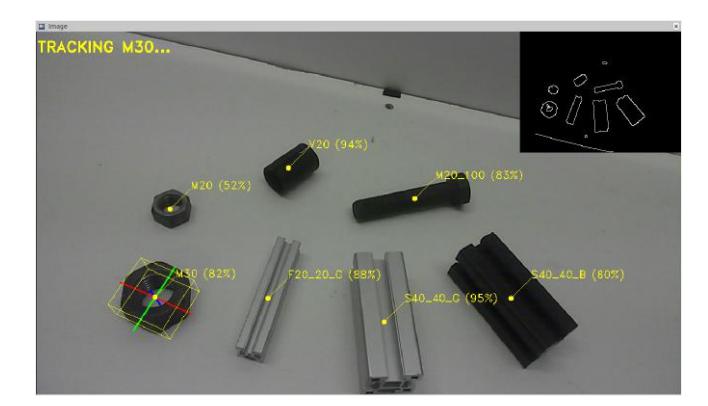
We use the Intel RealSense D435 for object recognition, which has one great advantage compared to similar devices. It works with a stereo- and infrared camera combined, which assures us more stable images. We use the RGBD-Pointcloud given by the camera to segment the image, to extract features and to classify the objects. To get the positions of the objects, we differentiate the points in our pointcloud by height. Then, the objects are classified using our neural network (which we trained with tensorflow) and a random forest classifier [12] [1]. Finally, the 3D-points are used to determine the object's position and orientation. In order to get a robust vision system that can handle miss-detections and which can memorise detected objects, all detections are clustered using a modified version of DBSCAN [4]. Each cluster is weighed, filtered and the positions are averaged. Then, the clusters are classified as objects or as failures. We are currently developing a new dynamic way to memorise and acquire accurate object positions. Displaying the objects as normal distributions and using a Kalman-filter to update their positions based on camera errors and observations[7].
3.5 Task planning
Our task planning is based on a graph based search. In each step all known service areas are used as possible navigation tasks. All objects on the back of the robot (there are up to three allowed) are used as possible placing tasks and the objects on the service area are used as grasping tasks. A greedy-based planning [10] is used up to a max depth and repeated until a complete plan is produced. The greedy algorithm is based on the cost function (see Eq. 1) taking the time to perform the task, the probability to fail and the expected output. For the navigation tasks the distances are pre-computed based on the known map. The manipulation time costs are averaged based the last respective manipulation action. When the state machine is not able to successfully recover a failure, the task is rescheduled with an increased probability to fail.
$$Score_{n+1} = \frac{Value_n + Value_{Action} \cdot \prod Chance_i}{\sum Cost_i}$$
3.6 State machine
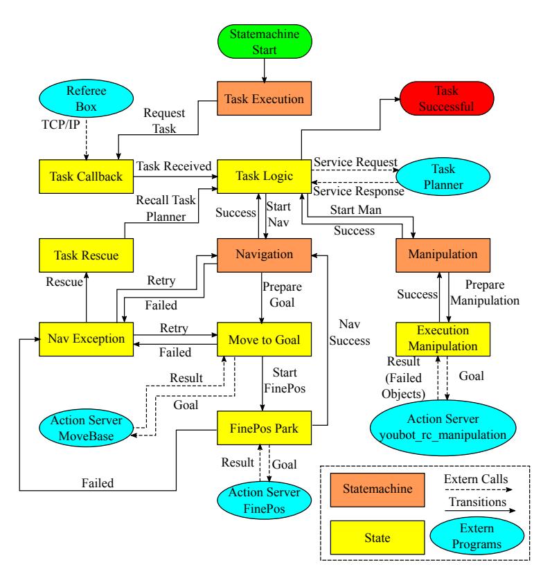
The state machine is written in C++ and ROS. Combining three different nodelets into one node gives us the possibility to optimise manipulation and navigation processes independent of each other. The state machine nodelet is used as an interface to the task planner, receiving new tasks and sending back failed tasks. This nodelet then passes the task information to the navigation or manipulation state machine. These are only responsible for deciding on which rudimentary operation (RO) to use. Since all RO's are implemented as action servers the nodelet can cancel tasks and reassign them if data in the world model suggests a change in action. The three nodelets are the main software parts (apart from sensor nodes) communicating with the world model to get information about their next task.
3.7 World model
The world model is used as a data storage system which communicates to the think-software (state machine and task planner). It stores all data which can be used for faster completion of tasks including speed of the robot, possible locations of objects, cost-maps, maps, robot position, type of workstations etc. A data saver is being developed, enabling the robot to recover from critical failures without human interference making the system more robust in regards of critical system errors and external influences. In the future the saved data can also be used for machine learning algorithms to optimise particular nodes, especially rudimentary operations.
3.8 Manipulation of dynamic objects
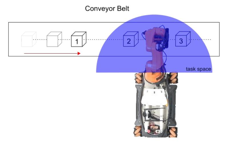
Our previous approach for gripping moving objects limited us. We could only grip two objects in one orientation. Since the approach was based on calculating a point where to grasp the object and then performing a standard grasp. Resulting in problems with orientations since the speed was not used to alter the grasp motion. The new approach differs after the object recognition (see Fig. 6 - at time 1 ). The robot measures the speed and position of the object. It calculates the point and time where the object reaches the task place(see Fig. 6 - at time 2 ). The arm moves above the calculated point. Waits for the object and accelerates until the arm is directly above the moving-object with the same speed. Overlapping the down movement with the current speed until gripping the object (see Fig. 6 - at time 3 ). The advantage of this approach is that while the calculated position and speed are correct every orientation and much higher objects can be gripped.
4 Acknowledgements
We would like to thank a couple of institutes and persons supporting our work. The team is supported by the Institute of Mechatronic Systems, the Institute of Systems Engineering – Real Time Systems Group, the student affairs office of the faculty of mechanical engineering, the society for the promotion of geodesy and geoinformatics and the Hannover Centre for Mechatronics. The team is being supervised by Marc Warnecke.
References
- Abadi, M., Barham, P., Chen, J., Chen, Z., Davis, A., Dean, J., Devin, M., Ghemawat, S., Irving, G., Isard, M., et al.: Tensorflow: a system for large-scale machine learning. In: OSDI. vol. 16, pp. 265–283 (2016)
- Alers, S., Claes, D., Fossel, J., Hennes, D., Tuyls, K., Weiss, G.: How to win robocup@work? the swarmlab@work approach revealed. In: RoboCup 2013: Robot World Cup XVII. pp. 147–158. Lecture Notes in Computer Science (2014)
- Bischoff, R., Huggenberger, U., Prassler, E.: Kuka youbot a mobile manipulator for research and education. In: ICRA (2011)
- Ester, M., Kriegel, H.P., S, J., Xu, X.: A density-based algorithm for discovering clusters in large spatial databases with noise. In: Proc. of 2nd International Conference on Knowledge Discovery and. pp. 226–231. AAAI Press (1996)
- Hart, P., Nilsson, N., Raphael, B.: A formal basis for the heuristic determination of minimum cost paths. Systems Science and Cybernetics, IEEE Transactions on 4(2), 100 –107 (july 1968)
- Ilon, B.: Directionally stable self propelled vehicle (Jul 17 1973), uS Patent 3,746,112
- Kalman, R.E.: A new approach to linear filtering and prediction problems. Journal of basic Engineering 82(1), 35–45 (1960)
- Leibold, S., Fregin, A., Kaczor, D., Kollmitz, M., El Menuawy, K., Popp, E., Kotlarski, J., Gaa, J., Munske, B.: Robocup@ work league winners 2012. In: RoboCup 2012: Robot soccer world cup XVI, pp. 65–76. Springer (2013)
- Munske, B., Kotlarski, J., Ortmaier, T.: The robotchallenge a research inspired practical lecture. In: Intelligent Robots and Systems (IROS), 2012 IEEE/RSJ International Conference on. pp. 1072–1077 (Oct 2012)
- Papadimitriou, C.H., Steiglitz, K.: Combinatorial Optimization: Algorithms and Complexity. Prentice-Hall, Inc., Upper Saddle River, NJ, USA (1982)
- Quigley, M., Conley, K., Gerkey, B.P., Faust, J., Foote, T., Leibs, J., Wheeler, R., Ng, A.Y.: Ros: an open-source robot operating system. In: ICRA Workshop on Open Source Software (2009)
- Statistics, L.B., Breiman, L.: Random forests. In: Machine Learning. pp. 5–32 (2001)