RoboCupRescue 2009 - Robot League Team C-Rescue (Japan)
Masaru Shimizu
School of Information Science and Technology, Chukyo University
http://japan.renesas.com/ · http://www.hitachisemiconductor.com/ · http://www.lantronix.com/ · http://www.iodata.jp/ · http://www.robotis.com/ · http://www.kondo-robot.com/ · http://www.aviosys.com.tw/products.htm · http://www.aichi-mi.com/ · http://www.figaro.co.jp/ · http://www.robocup.or.jp/2006JP/results/rr.htm · http://www.rescuesystem.org/robocuprescue/japan2004/japan-result2004.html
Abstract This year's our strategy is searching for sufferers inside wreckage or narrow space by small robot having 4 leg-crawlers. Now, we are developing a gimmick instead of trouble full crawler to run over obstacles. Simultaneously we are making an automatic generating a map function. It is indispensable to the practical rescue robot, too. We can get the location of the robots by using an electronic compass embedded in robots and dead reckoning with robot walking. We are making a robot-arm for our robot(We couldn't write in this paper about it). We made all informations(binary data, video, audio) being transmitted by the 802.11a wireless LAN between the robot and the host PC.
Introduction
This time, we will use one robot. It is a small size quadrupedal walking robot which is having crawlers at end of legs(Fig.1, Table1). We call the robot "4Legs" in this competition. We think the robot's size is important in the search mission on the disaster sites. So, we made miniature robots, and they can go into narrow spaces. 4Legs is the fourth generation of the quadruped robot in our laboratory. We participated in the RoboCup Japan open 2006 rescue robot league with the second generation one, and got the 3rd prize[1]. In addition, their old brother which was the first generation of quadruped robot got the 3rd prize in the RoboCup Japan open 2004, too[2]. These two results show that small robots having enough mobility and sensors can search sufferers as well as other middle or big size robots.
Our robots can measure temperature of the doubtful position by the non-contact type thermometer, and distinguishes the matter whether it is a sufferer, and reports a result to the operator. And, each robot can pick up CO2 in the air around him, and reports it to the operator, too.
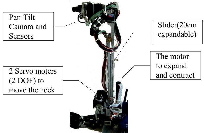
This time, our robot have a long neck. This neck can expand and contract. And we equipped a pan-tilt camera at the top of the neck. We can search into narrow spaces and higher places with this long neck.
And, we think that a practical rescue robot must have the function of automatic map generation. The conditions of the suffering spot and each sufferer's position and condition should be written into the map automatically. Otherwise, the operator of the robot can't concentrate attention on the sufferer's search work. As for the actual rescue activities, we must use many autonomous robots which need only a few commands. And then, the function which automatically generate a map is indispensable to the automation of the search work.
We composed a localization system by an electronic compass and a 3-Axial acceleration sensor and the dead reckoning. We get the horizontal direction of robot from the electronic compass, and get the vertical direction of robot from the 3-Axial acceleration sensor. And we can get the moving distance from the number of steps, and the distance information is not so dusty.
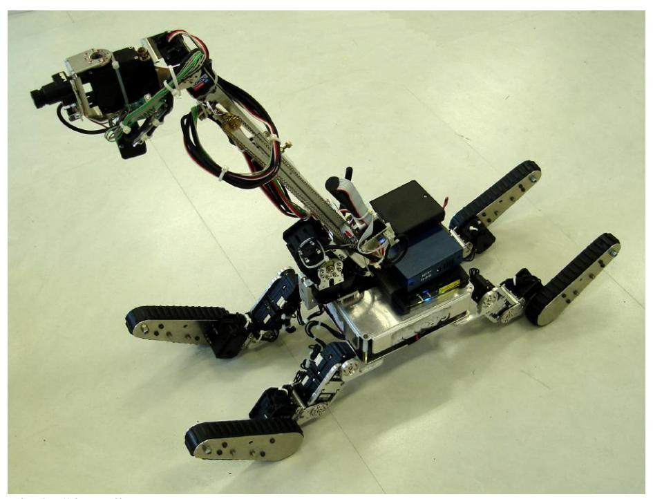
Table 1. Specifications of "4Legs"
| CPU(in robot) | SH2(7145F) 48MHz 3.3V (on the original PCB) | |
|---|---|---|
| Servo Motor (A) | DX-117 (ROBOTIS) x 12 (for leg) | |
| Servo Motor (B) | RX-28(ROBOTIS) x 4 (for crawler like gimmick) | |
| Servo Motor (C) | RX-28(ROBOTIS) x 2 (for neck moving) | |
| Servo Motor (D) | KRS-2350HV ICS Red Version x 2 (for front camera's pan-tilt) | |
| Frame | Original Aluminum Frames | |
| Wireless | 802.11a (with Ethernet Converter WLI3-TX1-AMG54) | |
| Camera | Network Camera (IPKamera9060AK) x 4 | |
| Sensor (A) | Electronic compass : HM55B (HITACHI) | |
| Sensor (B) | 3-Axial acceleration sensor : ACB302 (Star Micronics Inc.) | |
| Sensor (C) | CO2 sensor : TGS4161 (FIGARO ENGINEERING INC.) | |
| Sensor (D) | Infrared Ray sensor : RE-210 (NIPPON CERAMIC CO., LTD) | |
| Power Source | 14.8V Lithium Polymer (4Cells, 2680mA) x 1 | |
| Weight | About 5000g (with battery) | |
| Size | 720mm x 250mm(Front-Back x Side) At Neutral Pose height : 230mm (Head down) – 440mm (Plumb up head) |
|
| Moving speed | Max : 3cm/s |
1. Team Members and Their Contributions
We describe our team member here. But, this list is very temporary.
| • | Masaru Shimizu | Controller development |
|---|---|---|
| • | Masaru Shimizu | Mechanical design |
| • | Masaru Shimizu | Circuit and PCB design |
| • | Masaru Shimizu | Software development |
| • | Masaru Shimizu | Operator |
2. Operator Station Set-up and Break-Down (10 minutes)
We devised these methods shown in the following to do Set-Up or Break-Down in 5 minutes. This time, we'll use only one notebook PC for the operation. Therefore, we can make this set-up work becoming a simple and smart job. Our main devices are one robot, one notebook PC, one or two joy sticks, and one small printer(if need it).
We are expecting that the start of our system will be completed within 3 minutes by everyday's training.
Our Break-Down will be practiced so that it may be completed in 3 minutes.
3. Communications
We have to use a wireless device for 5.0 GHz(802.11a), because 802.11b/g has been crowded.
We are using Ethernet Converter which bridge a gap between wired LAN and wireless LAN, we can use one 802.11a channel for robot control data transfer and network camera's video and audio transfer(Table2). And we noticed that it's very simple way and it's good method for saving equipment space and power in robot and money (this year's construction is cheaper than last year's).
Two years ago, we had been using 1.2GHz AV transmitter and 2.4GHz wireless data modem. The wireless modem was good at size and robustness, but it was very expensive. It's a good lesson for us about wireless transmission.
Table 2. Radio frequency
| Rescue Robot League | ||||
|---|---|---|---|---|
| C-Rescue (JAPAN) | ||||
| Frequency | Channel/Band | Power (mW) | ||
| 5.0 GHz - 802.11a | Able to follow instruction | 2.3 mW/MHz |
4. Control Method and Human-Robot Interface
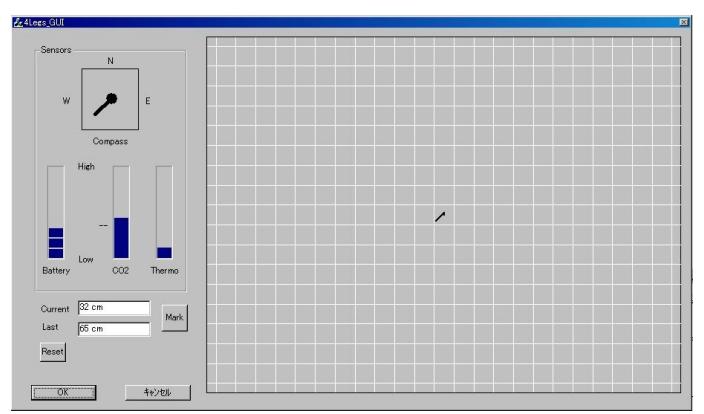
We describe the control method and the human robot interface in this chapter. An operator operates 4Legs by using the joy stick or the notebook PC's keyboard. The operator can watch the video image and hear the sound from the robot's network camera with web browser on the notebook PC. The operator can move the camera direction by pushing the joystick's buttons. The operator can watch the indicators of the robot's direction and outputs of CO2 sensor and Inferred rays sensor and battery's condition, too(Fig.2's left area). And, the path way of the robot is written into the map automatically(Fig.2's right area). The operator can set some marks to push the "Mark" button. Therefore, an operator can be concentrated on the investigation activities, and will be able to prepare a map for the presentation easily.
5. Map generation/printing
We made a localization system. And, the location of robot is plotted in the map(Fig.2). The map has grid line by 50cm, and we can measure the distance on the map. The operator can set some marks where found victims, too.
And, we will be able to stick the icons of the walls, the furniture and the obstacles on the map.
Finally, because of the map is a bitmap image, we can edit it on our program, and can print it with a miniature printer.
6. Sensors for Navigation and Localization
6. 1 Sensors for Navigation
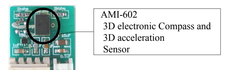
Our robot equips a compound sensor AMI-602. It includes a 3D electronic compass and a 3D acceleration sensor(Fig.3). And we can measure the distance by rolling of clawer or the number of steps of robot's walking. We can calculate the location from the combination of these informations. And the operator can know the current and past location of the robot and the current direction of the robot.
6. 2 Sensors for Localization
The sensor for localization is AMI-602.
7. Sensors for Victim Identification
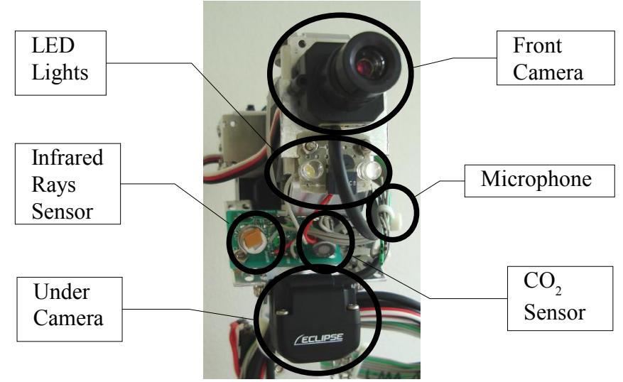
Our robot has 4 sensors for victim identification. The most important sensors are camera and microphone which bring the operator movies and sounds. This time, we'll use a network camera to get good condition video. And our robot have an infrared rays sensor and a CO2 sensor which are effective to feel invisible victims(Fig.4).
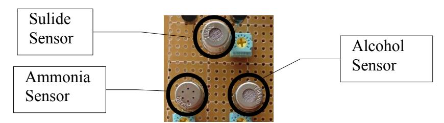
And we are developing a real victim detector. This sensor is a kind of GAS sensor array. Now we are using an alcohol sensor, an ammonia sensor , and a sulfide sensor(Fig. 5), and trying catch real victim's smell.
8. Robot Locomotion
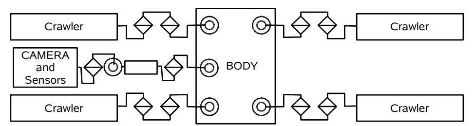
The movement mechanism of our robot is composed of four legs. We give each leg 3 degree of freedom(Fig.6). We made original frames to make the robot smaller. These legs move a robot repeating a simple pattern due to the open loop. Because algorithm is simple, legs can move quickly. The maximum walking speed of 4Legs is 20 cm/s. Cruising speed is 10 cm/s.
About the gimmick like crawler, now we are designing. The gimmick will consist of except endless rolling mechanisms but reciprocating motion mechanisms.
9. Other Mechanisms
We made original small frames for 4Legs to make it smaller. These frames were made by the support of the Chukyo University School of Computer and Cognitive Sciences Project Research Education Aid 2004.
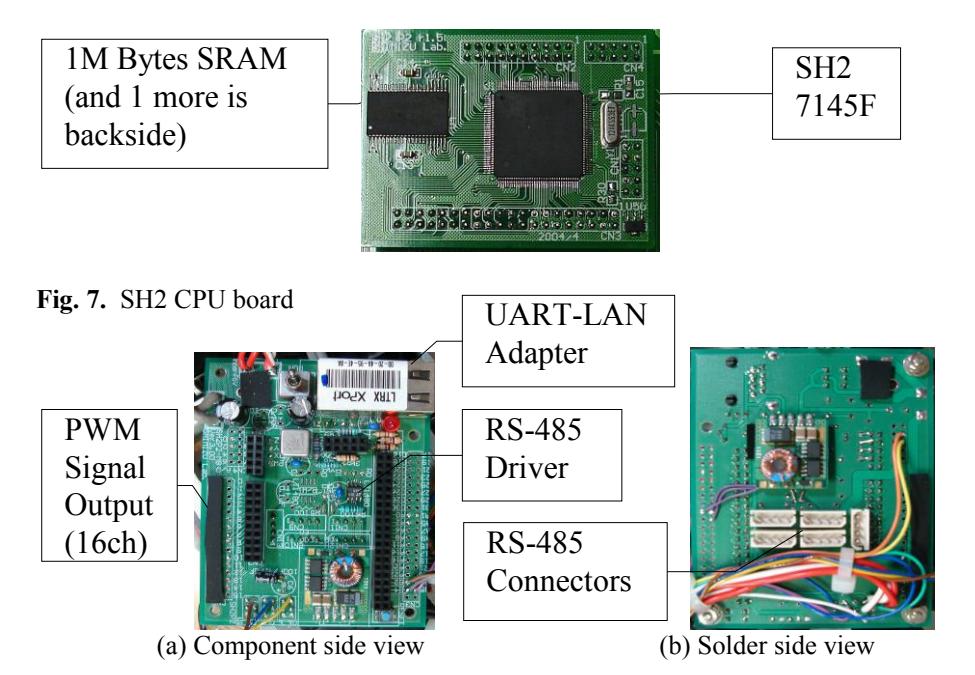
Another our unique devices are SH2 CPU board(Fig.7) and multipurpose Mother board(Fig.8) designed by our laboratory. We are using them in our education about components of robot.
This time, we made a long neck which can expand and contract(Fig. 9).
10. Team Training for Operation (Human Factors)
We will do the following practice.
- The practice to look for a suitable search area in the inside of the unfinished map.
- The practice to efficiently search for sufferers in the disaster site.
- The practice to ascertain conditions to fall into the movement impossibility.
- The practice to get out of the trap.
11. Possibility for Practical Application to Real Disaster Site
We think that the rescue robot handled in the actual disaster spot must have the performance which resists water, dust, oil, shock and high temperature. And, almost all rescue robot will be required miniaturization to search inside of the debris, too.
12. System Cost
We will show the cost of our system and main components in this chapter.
TOTAL SYSTEM COST (4Legs): 516,330yen (at least)
KEY PART NAME: CPU board (embedded in robot)
PART NUMBER: CPU:HD64F7145 , SRAM:HM62V8100LTTI-5 MANUFACTURER: CPU:Renesas Technology Corp, SRAM:Hitachi, Ltd. COST: CPU:5,536yen , SRAM:3,780yen x 2 = 7,560yen
WEBSITE: CPU:http://japan.renesas.com/,
SRAM:http://www.hitachisemiconductor.com/
DESCRIPTION/TIPS: This CPU is called SH-2. It's RISC 32Bit CPU. It have 16
PWM channels, 8 A/D ports, 4 UARTS, and many binary I/
O ports.
KEY PART NAME: Serial-Ether Converter
PART NUMBER: XPort-03R MANUFACTURER: LANTRONIX COST: 7,350 yen
WEBSITE: http://www.lantronix.com/
DESCRIPTION/TIPS: This device bridge a gap between RS232C and Ethernet.
KEY PART NAME: Ethernet – Wireless LAN Converter
PART NUMBER: WN-WAG/C MANUFACTURER: I-O DATA
COST: 14,000 yen
WEBSITE: http://www.iodata.jp/
DESCRIPTION/TIPS: This device bridge a gap between Ethernet and Wire-lessLAN (11a/11b/11g swichable). And this device include 3 ports HUB.
KEY PART NAME: Digital Servo(for leg)
PART NUMBER: DX-117 MANUFACTURER: ROBOTIS
COST: 23,824yen x 12 = 285,888 yen WEBSITE: http://www.robotis.com/
DESCRIPTION/TIPS: We can control this servo with data packet on the RS485.
KEY PART NAME: Digital Servo(for crawler and neck moving)
PART NUMBER: RX-28 MANUFACTURER: ROBOTIS
COST: 23,824yen x 6 = 142,944 yen WEBSITE: http://www.robotis.com/
DESCRIPTION/TIPS: We can control this servo with data packet on the RS485.
KEY PART NAME: Digital Servo PART NUMBER: KRS-2450ICS HV
MANUFACTURER: KONDO
COST: 15,000yen X 2 = 30,000 yen WEBSITE: http://www.kondo-robot.com/
DESCRIPTION/TIPS: This servomotor's power voltage is 12V - 17V. We can control this servo with PWM signal.
KEY PART NAME: Network Camera Server
PART NUMBER: IP Video 9100B MANUFACTURER: AVIOSYS COST: 17,500 yen
WEBSITE: http://www.aviosys.com.tw/products.htm
DESCRIPTION/TIPS: This is a web camera server having 4ch NTSC video inputs. It has a lot of flexibility to design equipping cameras.
KEY PART NAME: 3D electronic compass and 3D acceleration sensor
PART NUMBER: AMI-602
MANUFACTURER: AICHI STEEL CORPORATION
COST: 5,880 yen
WEBSITE: http://www.aichi-mi.com/
DESCRIPTION/TIPS: This device detects 3D earth magnetism and 3D accelera-tion. It's a very small device.
KEY PART NAME: CO2 sensor PART NUMBER: TGS4161
MANUFACTURER: FIGARO ENGINEERING INC.
COST: 5,000 yen
WEBSITE: http://www.figaro.co.jp/
DESCRIPTION/TIPS: This device detects CO2 gas in the air, and it's very small.
13. Lessons Learned
At the RoboCup2006, I got a big problem to be solved. It is the wireless trouble. In RC2006, I used 1.2GHz AV transmitter, 2.4GHz data modem, even as the committee strongly recommended using 802.11a. Before competition, I didn't think about the capability of wireless jam. But in competition, my robot did never work by poor wireless connection. This year, I am using 802.11a Wireless LAN converter instead of 2.4GHz data modem.
References
- http://www.robocup.or.jp/2006JP/results/rr.htm (cited 2008/3/21)
- http://www.rescuesystem.org/robocuprescue/japan2004/japan-result2004.html (cited 2008/3/21)