RoboCupRescue 2009 - Robot League Team RoboRescueTeam FH-Wels (Austria)
Raimund Edlinger, Andreas Pölzleithner, Walter Rokitansky, Michael Zauner, Bernhard Fahringer, Thomas Fink, Thomas Hatheier, Johannes Hieslmair, Harald Kneidinger
FH OOE Upper Austria Research & Development, Stelzhamerstr. 23, 4600 Wels Austria; FH OOE – Upper Austria University of Applied Sciences School of Engineering/Environmental/Sciences, Stelzhamerstr. 23, 4600 Wels Austria
http://www.fh-ooe.at/fh-oberoesterreich/fe/forschung.html · http://www.fh-ooe.at/campus-wels.html
Abstract This paper describes the work of the RoboRescueTeam FH-Wels developing and building an autonomous rescue robot. The team consists of research associates and students at the University of Applied Sciences Upper Austria.
This paper includes the preliminary results which are achieved so far about map building, localization and autonomous victim identification. Furthermore the implementation of 2D Laser Range Finder (LRF) and a novel mechanism with a dynamic drive system for locomotion is described. Additionally the construction of a modular robotic arm is introduced. A thermo camera and several other sensors are attached at the very end of this robotic arm which are used for victim detection.
Introduction
RoboRescueTeam FH-Wels [1] includes members which already have achieved experience by building autonomous robots for competitions. These robots were able to win competitions such as the Robot-Challenge in Vienna (AUT) the Robot SM in Gothenburg (SWE) and the RoboGames in San Francisco (USA). The robots also started at the Eurobot in La Ferté Bernard (FRA) and Heidelberg (GER).
The RoboCup Rescue League is a competition where autonomous robots navigate through an arena with different level of difficulty such as uneven underground, obstacles and stairs. According to those requirements the development of the robots is very complex and combines multiple disciplines such as mechanical engineering, electrical engineering and programming. The RoboCup Rescue League requires the highest demands on the motor and sensory abilities of the robots. The robot is developed specially for the use in the field of security and emergency application. The preliminary aim is to build an autonomous robot which is able to drive through an unstructured environment and search for victims. This includes generating a map of the environment and characterizing and locating victims as well as recognizing dangerous situation caused by fire and gas. The robot is supposed to act either autonomously or remote controlled by humans. Building a robot which is supposed to attend the RoboCup Rescue League requires high degree of versatility and experience which makes it difficult to start in this competition from scratch. At this early date when this paper is published is not fully realized. The mechanical systems of the robot including the robotic arm are assembled so far. Also the single modules such as the controller board and the peripheral system such as cameras and sensors are tested successfully separately. The next step is to assemble the modules to a distributed system and to develop algorithms according to the requirements. The system is planned to be finished by June 29th when the RoboCup Rescue competition takes place. The main focus concerns the exploration of all three different arenas of the competition by generating a two-dimensional map and the detection of victims. This solution is well suited for the red, orange and yellow arena. The approach to manage the orange arena is to develop a competitive algorithm where the robot navigates autonomously. The autonomous navigation on rough terrain is a challenging problem for mobile robot because it requires the ability to analyze the environment and make decision which parts can be traversed or need to be bypassed. This problem is commonly known as obstacle avoidance. Due to the design, the robot is very fast and agile so it is able to handle all of the three arenas. The detection and localization of victims is a high grade task for our team members.
Team Members and Their Contributions
• Raimund Edlinger Team Leader, Mechanical design, Controller design and Behaviors
• Walter Rokitansky Advisor • Michael Zauner Advisor
• Andreas Poelzleithner Mechanical design • Harald Kneidinger 2D-Mapping • Thomas Fink Localization
• Thomas Hatheier Victim Identification (Thermo camera)
• Johannes Hieslmair Vision
• Bernhard Fahringer Victim Identification (CO2-Sensor, Microphone)
• National Instruments Sponsor • LKR Ranshofen GmbH Sponsor
Operator Station Set-up and Break-Down (10 minutes)
The rescue robot is remote controlled by a lightweight laptop (HP Compaq 8510p) via a Logitech force feedback joystick. This so-called operator station is transported in a notebook case.
For transporting the robot itself it can be packed into a moveable case with wheels. All the very sensitive sensors such as thermo camera or laser range finder are packed separately in a case. The whole setup and breakdown procedure can be accomplished within less than 10 minutes. The procedure includes starting up the operation station, controlling the network status, checking if the sensor are working properly and to make sure that all actuators in the initial position.
Communications
For the communication between robot and operator station a D-Link DIR-635Range Booster N 650 router is used which is operating on the 2.4GHZ band. The wireless communication is used for both, the autonomous modus as well as for the remote control modus.
Wireless LAN Communication
| Rescue Robot League | |||||
|---|---|---|---|---|---|
| RoboRescueTeam (AUSTRIA) | |||||
| MODIFY TABLE TO NOTE ALL FREQENCIES THAT APPLY TO YOUR TEAM | |||||
| Frequency | Channel/Band | Power (mW) | |||
| 2.4 GHz - 802.11b/g/n |
Control Method and Human-Robot Interface
This section covers the teleoperation and autonomous control methods.
Teleoperation
During the remote controlled modus the motion of the robot is controlled by a Logitech force-feedback joystick which is connected to the operator station. Two fire wire cameras are mounted on the robot, one at the front and the other one at the rear side of the robot which gives images of the environment. Furthermore a thermo camera and two standard cameras are mounted on the top of a robotic arm and provide pictures for the operator. A graphical user interface (GUI) is about to be developed which is supposed to display current information of the terrain and environment. This includes the pictures of the thermo camera and the fire-wire cameras as well as the dates of the CO2 sensor, laser range finder and several other sensors. Additionally the operator gets important information about the robot's battery status and warnings for the obstacle avoidance.
Autonomous
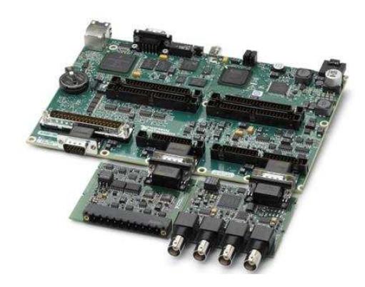
The robot is supposed to drive through the yellow arena fully autonomously. This requires a digital controller unit. For this robot he Single Board RIO from National Instruments [2] is used. It is a modular controlling system which in charge of monitoring the sensor data, controlling the actuators execution the main task for planning and navigation of the robot.
The NI Single-Board RIO [3] integrates an embedded real-time processor, a highperformance FPGA, and onboard analog and digital I/O on a single board. All I/Os are connected directly to the FPGA, providing low-level customization of timing and I/O signal processing. The FPGA is connected to the embedded real-time processor via a high-speed PCI bus.
Map generation/printing
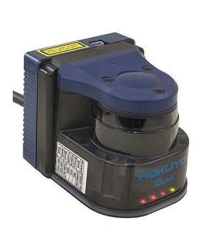
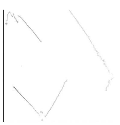
The two dimensional map generation is based on the acquired data of a laser range finder LRF UBG-04LX-F01 from the company Hokuyo [4] shown in figure 3. The light source of the sensor is an infrared laser with a wavelength of 785nm (laser class 1). The sensor is connected to the USB2.0 port of the wireless LAN router and communicates with the map building software which is programmed in LabView. The laser range finder obtains data of a scanning angle of 240°and a maximum distance of 4m. It is mounted on the front side of the robot and scans the area in cycles of 28 milliseconds. The measured data is stored as an array of polar coordinates and have a minimum angle resolution of 0.36° and a maximum distance accuracy of ±1%. Subsequently the data is transferred to Cartesian coordinates, rehashed by filters and combined with the acquired data of the IMU (described in Section 7) which determines the current position of the robot. To obtain the position of the items or victims the computer vision system of the robot calculates the coordinates to the point of interests. These coordinates are transferred by the map building software and inserted into the generated map of the arena. First testing procedures of static range scanning are made. The results are shown in figure 2.
Sensors for Navigation and Localization
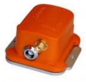
In order to detect the position and the attitude of the robot an inertial measurement unit, so called IMU, is used. The IMU which is employed in the robot, is the MTi from the company Xsens[5]. Figure 4 shows a picture of the MTi.
The MTi consists of three accelerometers, to determine the acceleration in the three axes and three rate sensors, to detect the attitude. Additionally three magnet sensors are used to achieve the direction of the earth magnetic field for referencing the sensor. The sensor has a built in Kalman-filter to provide drift free information of the attitude, calibrated acceleration and magnetic field information. Data can be transmitted either via USB or RS232. In this case the sensor is connected via USB to a wireless LAN router which transmits the data to the operator station where the data is processed by a program written in LabView. Determining the driven path is done by integrating the information of the acceleration twice.
The sensor also gives the value of the current altitude. It is very useful for the remote controlled mode, because the motion of the robot can be controlled easier. Furthermore the altitude is necessary for calculating the distance values of the laser-scanner.
Sensors for Victim Identification
This section covers the vision system, thermo vision system, and acoustic and gas sensors for victim identification.
Vision System
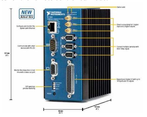
The vision system is based on three digital IIDC FireWire cameras connected to a National Instruments Compact Vision System 1456 [6]. For illumination two LUXEON LED rings are used. Each has a power of 7 watts and consists of six LEDs wit reflectors. Two cameras are mounted to the very end of the robotic arm and are set up as a stereo system. The remaining camera is mounted at the front of the robot which provides pictures for the remote controlled mode.
The Vision System NI 1456 is in charge of filter and streaming the images from the three Fire Wire cameras. It also allows analysing the light of the environment around the robot. In order to get a constant illumination level the brightness of the LEDs is controlled. This gives the advantage of a very stable and constant histogram which is important for an automatic detection of insured people.
The plan for the next month is to realize the detection of victims or obstacles with a SIFT2 algorithm [7]. CUDA makes is possible to run this algorithm on a NVIDIA GeForce 9800 GTX+ graphics card. It stands for Compute Unified Device Architecture and is a parallel computing architecture developed by NVIDIA.
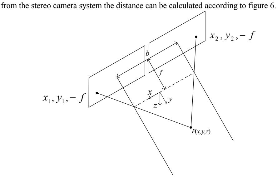
It is supposed to analyse a 15fps³ image stream from the stereo camera system. The stereo camera system provides information to generate a three dimensional model of the environment and locate the victims. By comparing points of the camera images
Assuming $y_1 = y_2$ the point P(x, y, z) can be calculated as:
$$x = \frac{b\frac{x_1 + x_2}{2}}{b + x_2 - x_1}$$
$$z = \frac{b\frac{y_1 + y_2}{2}}{b + x_2 - x_1}$$
$$z = \frac{-b f}{b + x_2 - x_1}$$
2 Scale-invariant feature transform
3 frames per seconds
Thermo Vision System
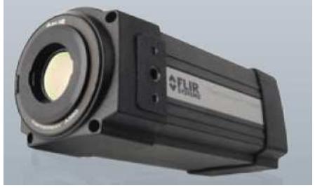
The core of thermo vision system is the FLIR[8] infrared thermo camera A320 which works in a range of 7.5µm up to 13µm wavelength. The camera uses an uncooled micro bolometer to detect the infrared radiation which is emitted by the objects in the observed area. The camera works on 30fps which also allows detecting the movement of objects precisely
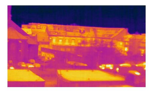
The data of the sampled information is sent via wireless LAN to the main computer where a program analyses the live stream. This program is also written in LabView. Figure 8 shows the picture of the thermo camera compared to the picture of a standard camera in figure 9.
It is planned to implement a smart algorithm which is supposed to detect interesting objects such as victims automatically. Therefore the picture is scanned for conspicuous areas. The objects in the picture should be found using the temperature information. On one hand victims can be classified by a certain body temperature on the other hand dangerous heat sources can be localized. The next step in the development process will be acquiring detailed information about the location of the object and to mark it as an interesting point in the created map. The distance between the robot and the detected object will be calculated using a "depth of focus" algorithm.
For the final solution algorithms are supposed to combine the pictures and their information of the different cameras.
Acoustic and Gas-Sensor
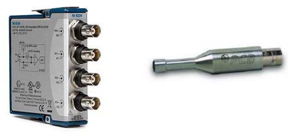
For the detection of acoustic signals the microphone 130D20 from PCB Piezotronics [9] is used. It is a pre-polarized condenser microphone with a built in pre amplifier. The range of measurable frequency is from 20Hz up to 15kHz which is basically the typical audible range of human. It is built into a very robust steel casing with a BNC connector on the rear side. For processing the audio signal, the microphone is connected to the analog-to-digital converter NI 9234 from National Instruments. It is a four channel signal acquisition module where each channel is sampled with a depth of 24 bit and a sampling rate of 50kS/s. This module is then connected to the National Instruments Single Board RIO where the signal is processed for detecting human voice. The incoming signal is first filtered by a digital high pass filter to get rid of noise and then the signal is Fourier-transformed to get the frequency spectrum. The microphone is mounted on the top of the robotic arm close to the cameras.
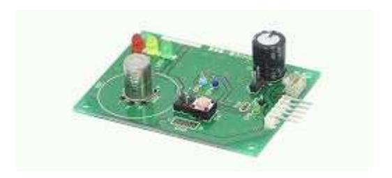
For detecting carbon dioxide the sensor the CDM4161A CO2 unit from Unitronic [10] is used. This highly miniaturized pre-calibrated CO2 sensor unit has low power consumption and no maintenance is required. As output the sensor unit provides an analog voltage level from 0,4V to 4V which is proportional to the carbon dioxide concentration in the air. Then this value is transformed into a ppm⁴ -value which denotes one part carbon dioxide per 10⁶ parts of air. The accuracy is 400ppm. The sensor is also mounted on the top of the robotic arm. Fig. 11 shows a picture of the sensor unit.
Robot Locomotion
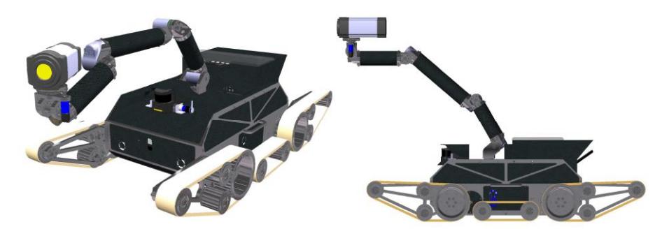
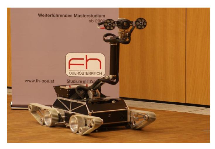
The locomotion of mobile robots in the undeveloped outskirt area is one of the most difficult demands for the system. On the one hand, as an outdoor robot it has to be fast and flexible on the other the vehicle has to deal with rough underground such as stones, gravel or stairs. Other important requirements are that the whole system is, on one hand robust, and on the other hand a lightweight construction to reduce the energy consumption and increase the agility. According to these requirements a drive system was developed which is shown in Fig. 12 and Fig. 13. The drive system basically consists of four pulley belts which are driven separately by DC-motors. Additionally the two belts on the front and the two belts on the rear side can rotate individually. This is important for tasks like driving over uneven underground and climbing stairs. The body of the vehicle basically consists of an aluminium frame. The gaps, which are for reducing weight, are covered with carbon composite sheets. The DCmotors and the gear boxes are located inside of the frame so they are protected against damage.
Other Mechanisms
A very important feature is the robotic arm which is mounted on the top of the vehicle. One thermo camera two standard cameras and several other sensors are mounted as payload at the very end of this arm. This makes it possible to reach exposed areas up to approximately 120cm above ground including the vehicle beneath. It is designed to carry a payload of approximately 2kg.The robotic arm has six degrees of freedom which are driven by DC-motors via worm gears. For reducing weight and increase the stability modern materials such as special aluminum alloys, magnesium and carbon composite are used. The links and joints are specially designed to be able to change the configuration of the arm easily by adding or removing links if it is required. Furthermore the bodies of the main links are realized by carbon composite tubes which can be replaced by a tube with different length. This makes it a modular system.
The measurement of the angular position of each joint and a forward kinematic model allows determining the position and orientation of the camera at the very end. For the next iteration an inverse kinematic model and a trajectory planning algorithm are planned.
Team Training for Operation (Human Factors)
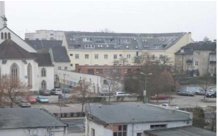
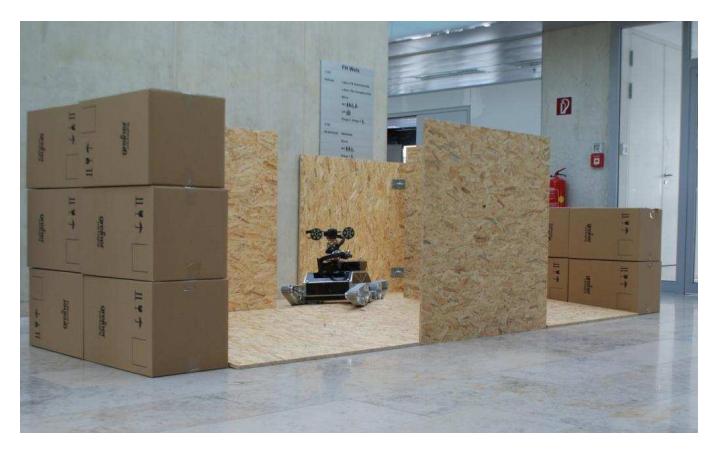
The navigation of the rescue robot in our real disaster environment, which is shown in Fig. 14, requires full knowledge of the function of the robot. So the remote controlling requires a special training and practicing for the operator to navigate the robot through the arena. Furthermore a large amount of practicing is necessary to control the 4 chain disk drives. Also the manipulation of the robot arm has to be learned by the operator. The team members are responsible for their contributions and to guarantee an accurate function of the developed algorithms. In the last month competitions are planned between the team members to in order to train operators for the RoboCup Championship.
Possibility for Practical Application to Real Disaster Site
The robotic system is suited to support rescue team for allocating human victims, fire and gas in the case of a real disaster. It is supposed to replace humans in dangerous situations. The motion system and the robotic arm which are mentioned above allow the robot to explore the operational area. For detecting victims and dangerous situations the cameras and sensors provide information of the environment.
Urban Search and Rescue (USAR) is a time critical task. Rescue teams have to explore a large terrain within a short amount of time in order to locate victims after a disaster. This advanced technology can assist rescue workers in four ways: (1) reduce personal risk to workers and dogs by entering unstable structures, (2) increase speed of response by penetrating ordinarily inaccessible voids, (3) increase efficiency and reliability by methodically searching areas with multiple sensors using algorithms guaranteed to provide a complete search in three dimensions, and (4) extend the reach of USAR specialists to go places that were otherwise inaccessible.
The team is in contact with ROSENBAUER Group [11] which is one of the world's largest manufacturers of fire fighting vehicles and after the competition we have to present the prototype of our rescue robot. With its wide range of municipal fire fighting vehicles we expect to force the development of our robot. In the next two year we will carry out a lot of field tests which include the exploration in different substrate, task for manipulation or buildings with risk of explosion hazard.
System Cost
The system cost table shows the components used in the robot and their costs.
System Cost
| Name | Part | Price in € | Nr. | Price Total in € |
|---|---|---|---|---|
| Robot Base - production | LKR Ranshofen | 12.500 | 12.500 | |
| Motion System | Haberkorn - Gears, drive belts | 200 | 4 | 800 |
| Robot Body | CFK-Carbo Tech | 579 | 1 | 579 |
| Accumulator | LiPO 25,9 V, 10AH | 260 | 2 | 520 |
| Laser Range Finder | Hokuyo UR-04LX-F01 | 2.280 | 1 | 2.280 |
| WLAN Router | D-Link 635 | 60 | 1 | 60 |
| Thermo camera | FLIR A320 | 10.500 | 1 | 10.500 |
| Drive-Motors | Faulhaber 3242G024 | 240 | 8 | 1.920 |
| Control System | National Instruments NI-CVS | - | 1 | sponsoring |
| - | NI Single Board RIO | - | 1 | sponsoring |
| IMU | Xsens – Inertial Measurement Unit | 2.100 | 1 | 2.100 |
| Motion Control | Elmo-SimplIQ TRIO | 1.000 | 5 | 5.000 |
| Acoustic Sensor | CAE - Microphone | 365 | 1 | 365 |
| Sonic Sensor | Devantech SRF 10 | 51 | 4 | 204 |
| Temperature Sensor | TPA 81 | 75 | 1 | 75 |
| CO2-Sensor | Unitronic CDM 4161 | 42 | 2 | 84 |
| Other mechanic parts | Bearings, Screws, Switches | - | - | 500 |
| Fire-Wire cameras | Unibrain | 100 | 3 | 300 |
| Laptop | HP Compaq 8510p | 1.800 | 1 | 1.800 |
| Robot Arm- production | LKR Ranshofen | - | - | sponsoring |
| Arm Tubes | CFK-Carbon Scout | 200 | 1 | 200 |
| Motors for Robot Arm | Faulhaber 3242G024 | 200 | 6 | 1.200 |
| Other mechanic parts for the Robot Arm | Mädler – Gears, RS-Components, Conrad | - | - | Ca. 1.500 |
| Sum Total | - | - | - | 42.600,00 |
Lessons Learned
After the competition is over, please use this section to add your thoughts on the lessons your learned from deploying your robot and watching others. Your system will change leading up to the event and during the event as you react to changes in your assumptions. This section should capture those changes (although you may also modify all the previous sections as well), and articulate the lessons you took from the experience which will refine your system design.
References
- Robo Racing Team: Homepage. http://rrt.fh-wels.at Online Resource (January 2009)
- National Instruments Ltd.: Company. http://ni.com Online Resource (February 2009)
- National Instruments Ltd.: SBRIO User Guide and Specifications. http://www.ni.com/pdf/manuals/375052a.pdf – Online Resource (February 2009)
- Hokuyo Automation CO. Ltd.: LRF UBG-04LX-F01 Specifications. http://www.hokuyoaut.jp/02sensor/07scanner/ubg_04lx_f01.html – Online Resource (December 2008)
- XSens Technologies B.V.: MTi Development Kit http://www.xsens.com/Static/Documents/UserUpload/Xleaflets/leaflet_MTi.pdf – Online Resource (January 2009)
- National Instruments Ltd.: CVS-1450 Series. http://www.ni.com/pdf/manuals/372290a.pdf Online Resource (November 2009)
- D. Lowe. Distinctive image feature from scale-invariant features, International Journal of Computer Vision (2004)
- FLIR Systems, Inc.: Company http://www.flir.com/map.cfm Online Resource (January 2009)
- CAE Engineering Ltd.: Microphone http://www.produktentwicklung.de/ Online Resource (October 2008)
- Unitronic Ltd.: CO2-Sensor http://www.unitronic.de/ Online Resource (October 2008)
- Rosenbauer Ltd.: Company. http://www.rosenbauer.com Online Resource (October 2008)