RoboCupRescue 2009 - Robot League Team
Micha Andriluka, Martin Friedmann, Stefan Kohlbrecher, Johannes Meyer, Karen Petersen, Christian Reinl, Peter Schauß, Paul Schnitzspan, Armin Strobel, Dirk Thomas, Anguelina Vatcheva, Oskar von Stryk
Department of Computer Science (1), Technische Universität Darmstadt, Karolinenplatz 5, D-64289 Darmstadt, Germany; Department of Mechanical Engineering (2), Technische Universität Darmstadt, Karolinenplatz 5, D-64289 Darmstadt, Germany
www.gkmm.tu-darmstadt.de/rescue · www.gkmm.de · http://www.mesa-robotics.com/
Abstract The Darmstadt Rescue Robot Team is a new team established from a PhD program funded by the German Research Foundation at TU Darmstadt. It combines expertise from Computer Science and Mechanical Engineering. Several team members have already contributed in the past to highly successful teams in the RoboCup four-legged and humanoid leagues.
Introduction
The Darmstadt Rescue Robot Team is a new team which was recently established within the PhD program "Cooperative, Adaptive and Responsive Monitoring in Mixed Mode Environments" (Research Training Group GRK 1362, www.gkmm.de) funded by the German Research Foundation (DFG). This program addresses two exciting and challenging research areas: (1) navigation and coordination of multiple autonomous vehicles to perform a common task possibly together with a human mission manager; and (2) monitoring in mixed mode environments that are characterized by the heterogeneity of their components in terms of resources, capabilities and connectivity. The participation in RoboCup Rescue is one of the first steps towards a heterogeneous real-world scenario. Driven by the goal of using heterogeneous cooperative hardware and software in disaster environments, a successful participation in RoboCup Rescue will be an important milestone for these efforts. The interdisciplinarity of our Research Training Group allows us to combine established knowledge and elaborated tools from different disciplines to develop new solutions in search and rescue applications in the long run.
The experience in hardware [1] and software [2] of autonomous robots has already been successfully applied to RoboCup soccer [3, 4], and there have been studies in simulation on cooperative control [5, 6]. Several members of the team have contributed to two top teams in the Four-Legged League (the German-Team) and the Humanoid League (Darmstadt Dribblers). Other members of the group are developing different computer vision algorithms for people detection and object recognition [7, 8] which can now be applied to the Search and Rescue scenario. In this group there is also a history of highly successful participation in recognition and perception challenges for computer vision. Finally, the team members from mechanical engineering are focusing on the design and experimental evaluation of unmanned aerial and ground vehicles for environmental monitoring and surveillance applications. They have recently participated in flight dynamics and autonomy competitions for micro aerial vehicles.
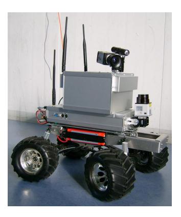
For the autonomy challenge the team plans to use robots based on a R/C model car Kyosho Twin Force as mobility platform (later on referred to as "Monstertruck", Fig. 1). Two of these robots are under development since 1.5 years. They are modified for better autonomous vehicle handling and enhanced with an onboard computer and a laser range finder. For the victim identification we developed a vision box, including a visual and a thermal camera. The vision box can be used as a stand-alone component for testing or can be attached to a robot to enable autonomous victim detection. In addition the team currently tries to purchase as soon as possible one of the only recently announced new tracked vehicle Matilda by Mesa Robotics (http://www.mesa-robotics.com/) and to include this for very rough terrain at RoboCup 2009.
1 Team Members and Their Contributions
- Karen Petersen: Team Leader, Behavior
- Armin Strobel and Johannes Meyer: Hardware Design, Sensor Fusion
- Paul Schnitzspan, Micha Andriluka and Oliver Schwahn: Visual Object Recognition
- Christian Reinl: Behavior
- Stefan Kohlbrecher: SLAM, GUI
- Anguelina Vatcheva: Hardware / Software integration
- Peter Schauß: Navigation, Path Planning
- Martin Friedmann: Simulation
- Dirk Thomas: Software Framework
- Oskar von Stryk: Advisor
2 Operator Station Set-up and Break-Down (10 minutes)
Currently our system consists of a lightweight robot that is able to work autonomously or can be remote controlled via a laptop or by radio control. The whole control equipment (even if we add a joystick or a gamepad) easily fits into a standard backpack and the Monstertruck can be carried by hand. To start a mission, the robot and the laptop have to be switched on, and the operator can connect to the robot via Wireless LAN.
3 Communications
Our communication concept is based on three different channels. A common wireless network is used for high-bandwidth data like video images or map information. Currently we use a 802.11g network, but it is possible to switch to 5 GHz or 802.11n if necessary. For data exchange with lower bandwidth demands, e.g. basic control commands or simple telemetry, the vehicle is additionally equipped with an 802.15.4 radio device. The operator station will be connected to a modified wireless access point which operates both, the wireless network and the 802.15.4 link. As the system is based on a customary R/C car, the signals to the motor and steering servos can be overridden by an 35 MHz R/C transmitter, even if the onboard controllers are no longer operational.
Table 1. communication channels used
| Rescue Robot League | ||||
|---|---|---|---|---|
| Darmstadt Rescue Robot Team (Germany) | ||||
| Technology | Frequency (selectable) | Power | Bandwith (nominal) | |
| WLAN 802.11g 2412 MHz (channel 1) | 32 mW (15 dBm) 54 MBit/s | |||
| 802.15.4 | 2435 MHz (channel 17) | 10 mW (10 dBm) 115 kBit/s | ||
| 35 MHz R/C | 35.080 MHz (channel 68) approx. 1 W | N/A |
4 Control Method and Human-Robot Interface
In general we focus more on autonomy than on mobility and manual control. So the ideal case is that the operator doesn't have to do anything during the mission besides monitoring what the robot is doing and confirming the victim information the robot provides. But anyway there are many ways how we can control the robot's behavior, and the operator can take over control at any time. Monitoring: The whole software system is based on RoboFrame [2]. It consist of two parts: (1) an Application (RoboApp) that is running on the robot, and (2) a Graphical User Interface (RoboGui) that is running on the Operator's computer. Every behavior decision and all messages between software modules, including sensor readings, can be monitored by the RoboGui. In that way every action of the robot is transparent to the operator.
The internal world model of the robot can be visualized in a configurable dialog. The user can choose to display the robot's position, sensor readings, ect. Displayed camera images can be enhanced with further information like the output of the thermal camera or estimated victim position.
Adjustable Autonomy: The operator can take over control at any time, but it is also planned to enable the robot to send help messages based on the current probability for fulfilling a task. To avoid having either full or no autonomy, there can be several solutions for the same subtask with varying level of autonomy.
To illustrate the idea of different levels of autonomy, consider the task of driving to a certain position. This can be either accomplished autonomously (klick on the map), or by following a predefined path (draw the path in the map), or by full remote control (use a joystick).
The idea of adjustable autonomy can also be applied to other tasks like object detection or mapping.
5 Map Generation/Printing
The robot solves the simultaneous localization and mapping (SLAM) problem by using a probabilistic particle filter / grid mapping approach, to allow for greater flexibility and robustness than allowed by a parametric / feature based approach (like e.g. extended Kalman filter SLAM). Every particle represents an estimated robot pose and holds an estimate of the map. The software is designed to be modular, thus different modules are easily exchangeable and all parameters can be adjusted at runtime via the GUI.
The input used for solving the SLAM problem are laser scans and the navigation filter (cf. section 6). The data provided by the navigation filter is used to update the particle distribution using the motion model, as well as for transformation of the laser scans to take into account the Euler angles of the laser scanner during acquisition of a scan.
The estimation of the robot's pose and the map is performed using the following consecutive steps:
Motion Update: Based on the estimated state and covariance from the navigation filter the particle distribution is updated, e.g. moves the particles according to odometry with additional noise due to not considered perturbations in the locomotion model like slippage. Optionally, a scan-matching process constrains the particle spread by the motion model.
Observation Update: The particle weights are updated with respect to the sensor model, using laser range data and the current estimated map to compute the observation likelihood for each particle.
Map Update: The gridmap is updated for each particle using a simple inverse sensor model.
(Optional) Resampling: The particle weights are normalized to sum to one and thus represent a valid probability distribution. The effective sample size [9] is used to decide if resampling is necessary.
The map can get annotated manually or automatically with information about hazmat symbols and victims. It can be converted and saved in the Geo-TIFF format.
6 Sensors for Navigation and Localization
Wheel Encoders: To measure the translational and rotational speed of the vehicle, all four wheels are equipped with incremental optical encoders. This odometry data is used especially for indoor navigation, but due to the inaccuracy additional feedback from other sensors is needed.
Laser Scanner: The Hokuyo URG04-LX laser scanner covers an arc of 240◦ with 0.36◦ resolution per scan. It has a maximum range of 4m and a maximum sample rate of 10Hz. The scanner unit can be tilted in order to balance the effects of uneven floor.
Inertial Measurement Unit: To get the attitude, the vehicle contains a 6DoF inertial sensor ADIS16350 by Analog Devices which measures accelerations and angular rates. This information is used for tilting the laser scanner and the camera unit.
Navigation filter: All sensor information is fused to an overall estimation of position, velocity and attitude of the vehicle by using an extended Kalman filter. Although Kalman filtering is a common and simple approach for robot navigation problems, it suffers amongst others from the resulting unimodal representation of the belief state. On the other side, the feedback from map-based localization, as described in section 5, can lead to ambiguities which contradict the Gaussian assumption. Our approach is to combine these two sources of information in a loosely-coupled way in order to gain a robust navigation solution.
7 Sensors for Victim Identification
Victim detection will be approached from several complementary directions. With team members working in computer vision we plan to leverage their extensive experience and prior work. Significant progress in visual object recognition and scene understanding now allows us to apply these methods to real-life conditions. The victim detection will be supported by the integration of other sensor types, like a thermal camera, CO2-sensor or microphone.
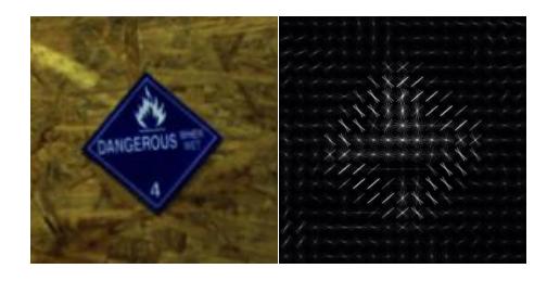
Vision-Based Recognition of Victims and Hazmat Symbols: The recognition of the objects is performed by using a combination of visual cues based on the gradients of image intensity. Such cues can be efficiently captured by a descriptor based on the histograms of oriented gradients (see Fig. 2 for illustration). First, the gradient magnitude and orientation are computed densely in the image. The local distributions of the gradient orientation are then captured by the histogram. Such histograms are then grouped with their neighbors and jointly normalized. The normalization and local pooling of gradient information significantly improves the stability of the description to viewpoint changes, noise and changes in illumination.
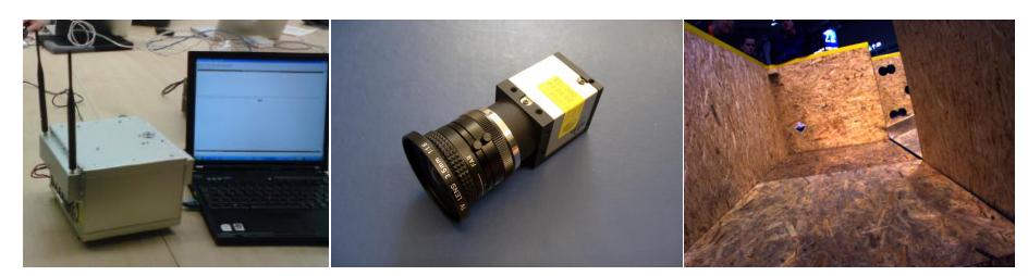
It has been recently demonstrated that visual information represented in this way combined with powerful machine learning techniques can be successfully applied to recognition of people in realistic conditions [10]. While showing good performance this approach also requires significant processing power. The onboard computer (Fig. 3) with an nVidia graphic card allows real-time feature computation and recognition with an implementation based on [11].
We plan to use the recognition system for detection of hazmat symbols at the victim sites (Fig. 3). The same system, but trained on the images of human body parts, will be used to recognize victims parts.
Multi-Cue Victim Detection: In addition to visual victim detection we will use a thermal camera as our secondary sensor. Thermal images often contain not only victims but also other warm objects, such as radiators or fire, so that thermal and visual recognition systems will deliver complimentary information. For the final victim verification we will also use acoustic and CO₂ sensors.
8 Robot Locomotion
Our vehicle is based on a Kyosho Twin Force RC model with a powerful and fast drive train. For indoor navigation we modified the drive train, the steering and the suspension because of the much higher weight.
4-wheel-drive: The 4-wheel-drive of this vehicle has one differential gear per axis and no middle differential gear. This ensures that if only three wheels have grip the vehicle is moving. To reduce the maximum speed and increase the strength we added a 1:5 gear.
4-wheel-steering: The front and rear wheels can be controlled independently to have three advantages over a normal 2-wheel-steering: (1) a smaller minimum turn radius (half of 2-wheel-steering), (2) the possibility that the rear wheels use the same trajectory as the front wheels (if both steering angles are the same) (3) the possibility to move sidewards (up to 35 degrees to the longitudinal axis of the vehicle).
Normally the rear wheels are set to the same steering angle as the front wheels, so that the resulting trajectories are identical and the risk of obstacle contact is reduced. With this vehicle we have a very flexible, mobile and powerful platform which additionally has the advantage of precise odometry.
9 Other Mechanisms
9.1 Established Technologies from RoboCup Experience
From 2001 till 2008 the Darmstadt Dribbling Dackels participated in the 4-legged soccer league as a part of the German Team and won the world championship in 2004, 2005 and 2008. Since 2004 the Darmstadt Dribblers participate successfully in the humanoid kid-size league. Although Search and Rescue is a totally different application than soccer, the Darmstadt Rescue Robot Teams can make use of the experiences from the soccer teams and many tools that were developed in these teams can also be applied for Search and Rescue.
RoboFrame: Our software is based on RoboFrame [2], a software framework that supports teams of heterogeneous autonomous lightweight robots. RoboFrame supports modular software development and takes care of the communication between sensors, actuators and software modules.
XABSL: The high-level behavior is described as a hierarchical state machine with the Extensible Agent Behavior Specification Language XABSL [12]. This allows to easily extend the behavior and to reuse existing parts in different contexts. XABSL was originally developed for the behavior of soccer robots, but it was also applied to team cooperation of heterogeneous robots [13].
MuRoSimF: The Multi-Robot-Simulation-Framework [14] provides components for the simulation of a robot's motion and sensing capabilities on different levels of detail. MuRoSimF allows to test each component of the software separately by replacing all other part by ground truth data. After component testing, before using the real hardware, the whole system can either be tested in a MuRoSimF based simulation or with the established simulator USARsim [15].
9.2 Hardware Modularity
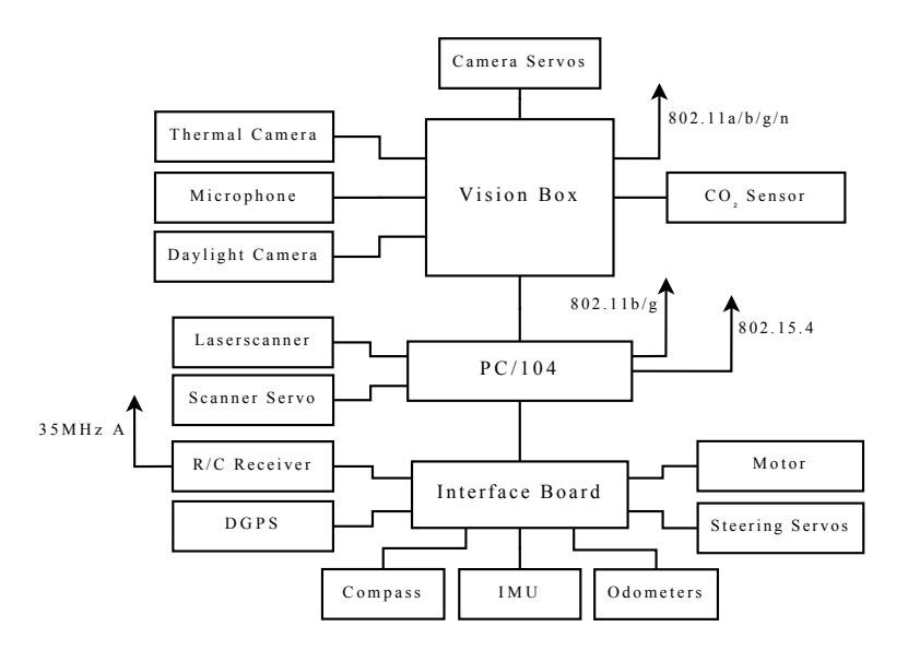
The complete Hardware structure of our vehicle is shown in Fig.4. The intrinsic sensors and actuators are connected via the interface board to a PC/104 board. The extrinsic sensors are connected to the PC/104 or to the vision box. The sensors connected to the vision box are primarily used for detection of victims and hazmat symbols. All these sensors are also physically connected to the vision box. This allows using the vision box with the corresponding sensors alone for testing and developing of the vision algorithms or on other vehicles.
10 Team Training for Operation (Human Factors)
Our User Interface, RoboGui, is based on the software framework RoboFrame [2], which is a very general framework which enables the development of modular software, that can easily be ported to other platforms. But due to this generality, the User Interface cannot be specialized to a specific system, which leads to the fact that a new user needs some time for getting familiar with the system.
11 Possibility for Practical Application to Real Disaster Site
The Monstertruck is a fast vehicle that allows a precise locomotion. The low weight is a big advantage for a fast and flexible set-up of the whole system. The most critical points are movement in a very rough terrain and its sensitivity against some basic risks like humidity. We plan to overcome this by using the tracked vehicle Matilda by Mesa Robotics (http://www.mesa-robotics.com/).
The strength of our approach is the elaborated reusable software [2], which is a reliable base for developing and extending our system. For practical application to real disaster sites we have to improve abilities in (partial) autonomy and plan to enhance the system by other existing components like an an UAV (Quadrocopter) and (mobile) sensor nodes. We hope to be able to give useful, flexible assistance to operators in managing disaster scenario within a few years.
12 System Cost
Vehicle
| Component | Model | Price |
|---|---|---|
| PC/104 Computer Lippert Cool LiteRunner | 250 EUR | |
| R/C Car | Kyosho Twin Force | 300 EUR |
| Odometer | Selfmade | 200 EUR |
| Interfaceboard | Selfmade | 200 EUR |
| IMU | ADIS16350 | 300 EUR |
| Magnetometer | HM55B | 25 EUR |
| Laser Scanner | URG-04LX | 1900 EUR |
| Power Supply | picoPSU-120 + Misc. | 100 EUR |
| Batteries | 6 Cell LiPo 5000mAh | 240 EUR |
| Misc. | 300 EUR |
Vision Box
| Embedded PC | Core 2 Duo | 700 EUR |
|---|---|---|
| Visual Camera | uEye UI-2230RE | 700 EUR |
| Thermal Camera | ThermalEye 3600AS | 3100 EUR |
| Servos | Robotis RX-10 | 160 EUR |
| Misc. | 200 EUR | |
| Total Cost | 8675 EUR |
References
- M. Friedmann, S. Petters, M. Risler, H. Sakamoto, D. Thomas, and O. von Stryk. New autonomous, four-legged and humanoid robots for research and education. In Workshop Proceedings of the Intl. Conf. on Simulation, Modeling and Programming for Autonomous Robots, pages 570–579, Venice (Italy), November 3-4 2008.
- S. Petters, D. Thomas, and O. von Stryk. Roboframe a modular software framework for lightweight autonomous robots. In Proc. Workshop on Measures and Procedures for the Evaluation of Robot Architectures and Middleware of the 2007 IEEE/RSJ Int. Conf. on Intelligent Robots and Systems, 2007.
- M. Friedmann, K. Petersen, S. Petters, K. Radkhah, D. Thomas, and O. von Stryk. Darmstadt dribblers: Team description for humanoid kidsize league of robocup 2008. Technical report, Technische Universität Darmstadt, 2008.
- D. Becker, J. Brose, D. Göhring, M. Jüngel, M. Risler, and T. Röfer. Germanteam 2008 - the german national robocup team. Technical report, DFKI Bremen, TU Darmstadt, HU Berlin, 2008.
- Christian Reinl and Oskar von Stryk. Optimal control of multi-vehicle systems under communication constraints using mixed-integer linear programming. In Proc. of the. 1st Intl. Conf. on Robot Communication and Coordination (RoboComm), Athens, Greece, Oct. 15-17 2007. ICST.
- K.Listmann, M. Masalawala, and J. Adamy. Consensus for formation control of nonholonomic mobile robots. In Proc. of the IEEE Intl. Conf. on Robotics and Automation (accepted for publication), 2009.
- M. Andriluka, S. Roth, and B. Schiele. People-tracking-by-detection and peopledetection-by-tracking. In IEEE Conf. on Computer Vision and Pattern Recognition (CVPR'08), 2008.
- P. Schnitzspan, M. Fritz, and B. Schiele. Hierarchical support vector random fields: Joint training to combine local and global features. In Europoean Conf. on Computer Vision (ECCV 2008), October, 2008.
- G. Grisetti, C. Stachniss, and W. Burgard. Improved techniques for grid mapping with rao-blackwellized particle filters. IEEE Transactions on Robotics, 2007.
- N. Dalal and B. Triggs. Histograms of oriented gradients for human detection. In IEEE Conf. on Computer Vision and Pattern Recognition (CVPR'05), 2005.
- C. Wojek, G. Dorkó, A. Schulz, and B. Schiele. Sliding-windows for rapid object class localization: A parallel technique. In DAGM-Symposium, pages 71–81, 2008.
- M. Lötzsch, M. Risler, and M. Jüngel. XABSL a pragmatic approach to behavior engineering. In Proc. of IEEE/RSJ Intl. Conf. of Intelligent Robots and Systems (IROS), pages 5124–5129, Beijing, China, 2006.
- J. Kiener and O. von Stryk. Cooperation of heterogeneous, autonomous robots: A case study of humanoid and wheeled robots. In Proc. IEEE/RSJ Intl. Conf. on Intelligent Robots and Systems (IROS), pages 959–964, 2007.
- M. Friedmann, K. Petersen, and O. von Stryk. Simulation of multi-robot teams with flexible level of detail. In Simulation, Modeling and Programming for Autonomous Robots (SIMPAR 2008), pages 29–40, Venice, Italy, November 2008.
- S. Balakirsky, C. Scrapper, S. Carpin, and M. Lewis. Usarsim: providing a framework for multi-robot performance evaluation. In Proceedings of PerMIS, 2006.