RoboCupRescue 2010 - Robot League Team AriAnA & AVA (Iran + Malaysia)
Amir H. Soltanzadeh, Ahmad Chitsazan, Sharifah Azizah Sayeed A. Ghazali
Robotics Research Laboratory Engineering School, Niayesh Campus Islamic Azad University of Central Tehran Branch Pounak Sqr., Chaharbagh Ave., Tehran, 14687 Iran; AVA STRATEGIC ALLIANCE 23-3rd, Jalan 5/109F, Plaza Danau 2, Taman Danau Desa 58100 Kuala Lumpur, Malaysia
http://robot.iauctb.ac.ir · http://robotics.ava-sa.com.my
Abstract This document describes AriAnA & AVA rescue robot team and its approaches for RoboCup 2010. The team consists of two main sub-groups: An Iranian part, AriAnA which works on developing mechatronical layers of high mobility robots and a Malaysian part, AVA concentrating on AI problems. This year we have focused on multi-robot 3D mapping which will be implemented on a team of three heterogeneous tracked robots consisting of one autonomous and two advanced mobility tele-operated robots. We have also planned to demonstrate a new map representing method using Head Mounted Display.
Introduction
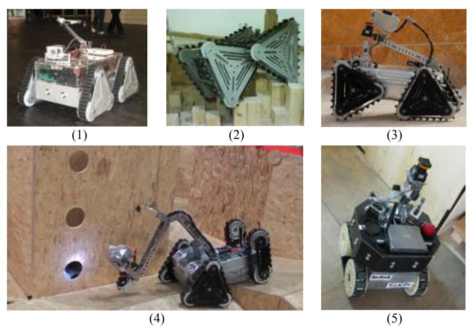
AriAnA & AVA rescue robot team is a collaboration between an Iranian group, AriAnA which represents Islamic Azad University of Central Tehran Branch (IAUCTB) and a Malaysian group, AVA belonging to AVA Strategic Alliance. Since 2006 AriAnA actively works on developing mechatronical layers of high mobility robots (i.e. hybrid locomotion, power management, semi-active controlling) while AVA is basically interested in intelligent Human Robot Interaction (HRI) systems. These groups began cooperating together before RoboCup 2009 (RC09) which led to participating as a joined team in the competitions and this was appreciated by Rescue Robot League (RRL) committee in opening team leader meeting. After our acceptable performance as a joined team in RC09, we decided to keep on our cooperation but, now as one multi-national team. Figure 1 shows our robots built since 2006.
Although our both sub-groups use an identical robotic platform (ALPHA) in physical tests, we utilize Player/Stage [1], a widely used open source robotic server to reduce dependency of software layer to underlying hardware.
This year we have concentrated on developing the well designed SLAM6D algorithm [2] as a basis of our multi-robot 3D mapping system which will be implemented on a team of three heterogeneous tracked robots including one fully autonomous robot (DELTA) besides two tele-operated ones (ALPHA and BETA). We have also planned to demonstrate a new 3D map representing method that we call it "Virtual Inspection" using Head Mounted Display (HMD).
1. Team Members and Their Contributions
From the following list only ten people will be attending in Singapore:
• Dr. Hossein Mahbadi Advisor, Head of robotics lab @ IAUCTB
• Dr. Andreas Neuchter Technical advisor (Jacobs Uni., Germany) • Dr. Farhad Tabatabai Ghomshe Technical advisor (Polytechnic, Iran)
• Amir H. Soltanzadeh Team leader, Technical manager
• Sharifah Azizah S. A. Ghazali Team manager (Malaysian side) • Ahmad Chitsazan Team manager (Iranian side) • Yaser Chitsazan Mechanics (Drivetrain)
• Amir Hossein Rajabi Mechanics (Powertrain)
• Amin Kazemi Mechanics (Manipulator) • Nima Sayaf Mechanics (Manipulator) • Golnaz Eftekhari Control (Reactive behavior)
• Alireza Amini Sohi Electronics (Hardware implementation) • Hasan Gholami Electronics (Hardware implementation) • Mehdi Soltanzadeh Software (Infrastructure, SLAM), Operator
• Hedieh Vahabi Ahooie Software (HRI, GUI)
• Mina Ghofrani Software (Exploration, Navigation) • Zeinab Arshian Software (Exploration, Navigation) • Mohammad Mazinani Software (Victim detection) • Mehdi Torshani Software (Victim detection) • Ellias Saidin Software (HRI, GUI)
• Andrew Uong Yeo Pau Software (Terrain classification)
• Kanesan Muthusamy Software (HRI, GUI)
• Barkawi Sahari Software (Exploration, Navigation)
• Tejinder Singh Software (SLAM)
With our special thanks to:
• IAUCTB Sponsor • ISOP Co. Sponsor • AVA Strategic Alliance Sponsor
And many appreciations to all former members of AriAnA rescue robot team.
2. Operator Station Set-up and Break-Down (10 minutes)
As in previous year, we use a custom designed Operator Control Unit (OCU) for fast set-up and break-down. This OCU currently consists of two laptops, HMD, gamepad, access point, Ethernet switch, power system and a pair of antennas.
We will carry the OCU and our robots to warm zone (next to the arena) using a trolley five minutes before each mission. Then we will turn the entire system on to perform automatic system check up. The system will remain powered up on "hot stand-by" until our mission starts. This set-up strategy is similar to what had been applied in 9/11 Urban Search And Rescue (USAR) missions [3].
When a mission starts, two team members put the robots in start point and other two members carry the OCU to operator control station. Once whole devices are placed in their right places, the operator starts controlling. This is done in less than 2 minutes.
At the end of each mission, the operator has two specific tasks: stopping the system and delivering mission data while two members are taking the robots out of the arena. The break-down procedure takes about 5 minutes.
3. Communications
Each robot has a 5 GHz IEEE802.11a Access Point/Bridge with a pair of external antennas to exchange data (e.g. high level control commands, sensor data and digital audio/video) with another one in OCU.
We use channel 36 as our default setting (Table 1) but it can easily be changed to any possible channel if it is needed.
Table 1. Used communication frequencies
| Rescue Robot League | |||
|---|---|---|---|
| ARIANA & AVA (IRAN + MALAYSIA) | |||
| Frequency | Channel/Band | Power (mW) | |
| 5.0 GHz - 802.11a | 36-64 (selectable) | 50 |
4. Control Method and Human-Robot Interface
As stated before, we will deploy one autonomous and two high mobility tele-operated robots in the arena. One of the tele-operated robots (ALPHA) can perform autonomous behaviors to be capable of traversing the radio dropout zone. Due to diversity of autonomy levels, theses robots have different sensor/actuator arrangements. As an instance, Fig. 2 illustrates hardware block diagram of our tele-operated robot in RC09.
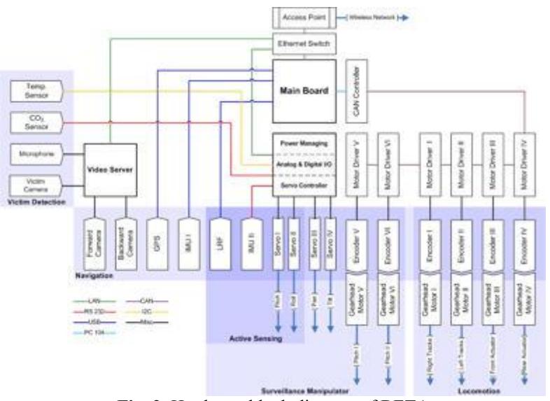
The core of this block diagram consists of an FPGA based controller and a main board which is a PC/104+ compatible, fanless, ruggedized Pentium M 1.4 GHz industrial computer with 2MB L2 cache, 1GB DDRAM and 2 GB Compact Flash (CF). A light Linux (Ubuntu 9.4 Server Edition) is installed on the CF to run robot control software.
4.1. Robotic Server
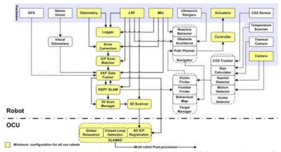
In order to reduce dependency of software architecture (Fig. 3) to its underlying hardware, we take advantage of Player robotic server. Player is a device server that provides a powerful, flexible interface to a variety of sensors and actuators. Because Player uses a TCP socket-based client/server model, robot control programs can be written in any programming language and can execute on any computer with network connectivity to the robot. In addition, Player supports multiple concurrent client connections to devices, creating new possibilities for distributed and collaborative sensing and control [4].
Additionally, Player supports two simulation environments namely Stage and Gazebo to model all Player supported devices in 2D and 3D environments respectively. This important capability lets us to develop our control software with no need to real robots during primitive tests.
4.2. Adjustable Autonomy
To reduce complexity of multi robot controlling, we are implementing an adjustable autonomy approach. Using this method, operator may enter to the robot control loop when it is needed. The available autonomy modes are:
- Teleoperation: no sensors are used to help keep the robot from bumping into objects
- Safe: teleoperation with obstacle avoidance provided by the system
- Shared: semi-autonomous navigation with obstacle avoidance where the user communicates his desires at points in the route where a choice must be made or can otherwise bias the robot's travel direction
- Follow: robot follows its moving leader and avoids collision
- Full autonomous: robot chooses a target point (based on Frontier Exploration algorithm [5]) to which it then safely navigates
4.2. HRI
Obviously, design of HRI directly affects operator's ability to understand the current situation, make decisions and provide high level commands to the robotic system [6]. As a key point, we need to appreciate the operator's requirements and the way of presenting them to him/her [7]. In this order, we are modifying our previous HRI system based on the experiences obtained in RC09.
Whereas the operator should control several robots at a same time, we set a laptop for mission controlling in which a 3D global map and victims' information are displayed while another laptop gives basic information for robot controlling (i.e. realtime status of all active robots).
The operator can control the tele-operate robots using a very popular gamepad (Xbox-360). To improve the operator's concentration, we take advantage of a state of the art high resolution HMD with transparent displays. This HMD has a built in IMU based head tracker and we use it to control pan/tilting cameras during tele-operation.
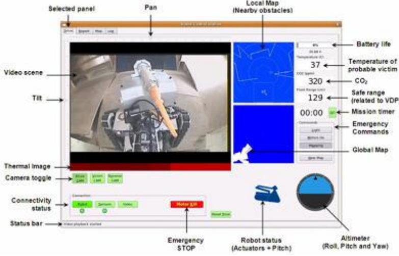
An easy to understand Graphical User Interface (GUI) based on our previous video centric GUI (Fig. 4) [8] is displayed on the HMD. Nevertheless, the operator is able to focus on the laptops to get more information or type something.
5. Map generation/printing
Our mapping system comprises of two main components: an onboard Occupancy Grid (OG) mapping which individually runs on each robot and a multi-robot 3D consistent global map generator running on the OCU. This 3D map is not sent to the robots; therefore, they should rely on their own 2D maps for autonomous navigation. Furthermore, the OG maps provide more accurate pose estimations for 3D mapping.
5.1. Occupancy Grid Mapping
The 2D mapping module is based on recently well known GMapping software [9] which uses grid-based SLAM algorithm with Rao-Blackwellized Particle Filters (RBPF) by adaptive proposals and selective resampling [10]. Practical experiments have shown robustness of this algorithm [11] in which every particle represents a hypothesis of robot pose besides a map. However, a number of minor modifications should be applied to reduce the amount of particles because of the significant overhead associated with each particle.
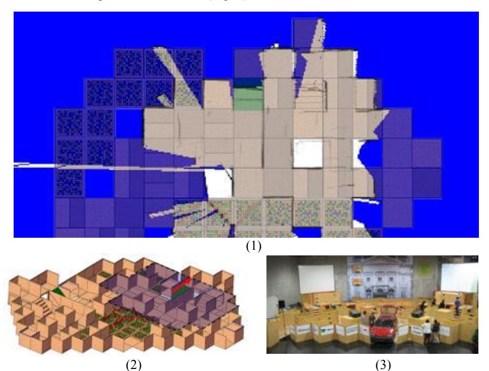
In RC09 we used 30 particles within an $800 \times 800$ cells grid with a grid cell size of $5 \times 5$ cm2 to map a $40 \times 40$ m2 area (Fig. 5).
5.2. 3D Mapping
As stated before, our 3D mapping system is based on SLAM6D algorithm [12] which is developed by Dr. Andreas Nuechter et. al. in Fraunhofer Institute for Autonomous Intelligent Systems (AIS, Sankt Augustin). This algorithm was demonstrated in several RC competitions and the representative team (Kurt 3D) won the best of class in autonomy award in 2004.
We are modifying this algorithm to make it capable of generating one global map of three robots. For simplicity, each robot's map is generated independently in a common frame of reference. Therefore, we need three SLAM6D algorithms running in parallel and an initial 6D pose correction between these three maps for aligning their reference frames. The entire 3D mapping will be carried out on a Lenovo Thinkpad X200 (2.4GHz Core 2 Duo Processor with 2GB RAM) laptop.
5.3. Accurate Pose Estimation
The registration process of SLAM algorithms need a pose estimation (in 3D for RBPF SLAM and in 6D for SLAM6D) of where the recent scan was taken relative to the pose of the previous or some other earlier scans. To improve accuracy of this pose estimation, we utilize a variety of techniques beside typical odomery including:
Laser Odometry
A fast Iterative Closest Point (ICP) scan matching method [13] is used to estimate robot's position in horizontal world plane by aligning consecutive scans from the laser rangefinder.
IMU Odometry
A primitive 6D pose estimation is obtained by double integration of acceleration measurements using one of two IMU's placed on each robot.
Visual Odometry
To have more accurate pose estimation within currently non-static RC RRL arena, we are developing an open source stereo vision based visual odomtery. It finds suitable image features for tracking and matches them frame by frame. Having depth of these points, we can compute a likely 6D pose for each frame.
EKF Data Fusion
After obtaining position estimations by several individual methods, these estimates can then be used in a sensor-independent manner for accurate state estimation. An open source Extended Kalman Filter (EKF) with a 6D model fuses the relative position estimates of encoder, IMU, laser, stereo odometries.
6. Sensors for Navigation and Localization
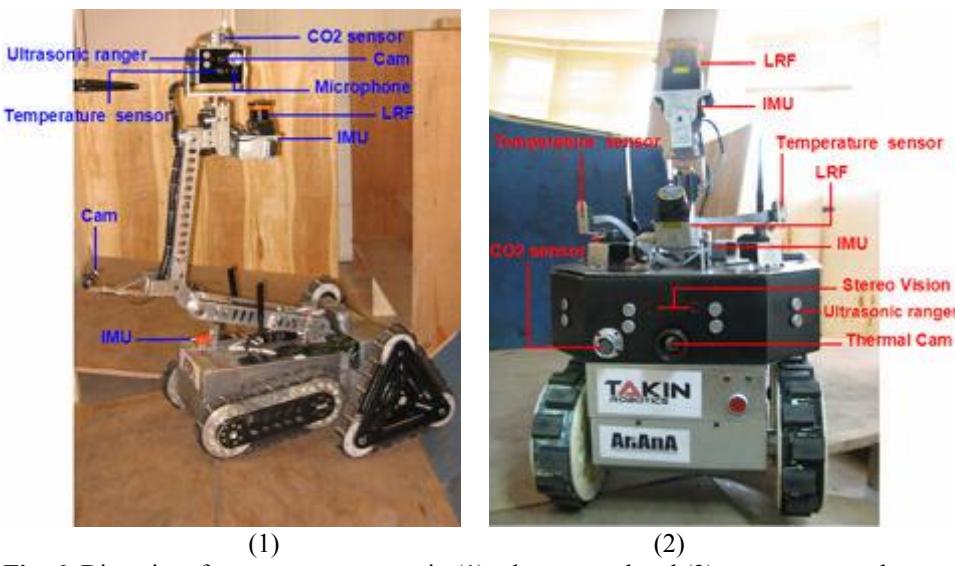
As it was stated before, we use three heterogeneous robots for distinctive purposes. However, their sensor payloads are different combinations of the following devices (Fig. 6):
Camera
Two identical wide angle 1/3" high resolution Sony CCD color cameras provide a fine environmental awareness for tele-operation. Videos of these cameras are converted to MPEG-4 format and streamed over Ethernet with Real Time Streaming Protocol (RTSP) by means of a MOXA V351 video server.
Optical Shaft Encoder
Our locomotion platforms are powered by Maxon Gearhead DC motors coupled to HEDL 5540 optical shaft encoders. The controllers (Maxon EPOS) connected to these encoders send motors' rotation data (i.e. position, velocity and acceleration) to the motherboard via CAN interface.
LRF
Each robot has a Hokoyo UTM-30 LX scanning Laser Range Finder (LRF). This long range (up to 30 m), wide angle (270°) and fast (40 Hz) LRF is mounted on a gimbaltype servo mechanism to keep it horizontal (in world frame) while 2D scanning [14] and to rotate it during 3D scanning. The LRF rotates in top-yaw style [15] to increase the overlapped area of two consecutive scans also, to acquire full hemisphere point cloud in a 180 deg. rotation.
It should be mentioned that the autonomous robot, ALPHA utilizes a pitching Hokoyo URG-04 LX LRF in addition to UTM for real-time train classification.
IMU
Each robot has two different types of IMU's: An Xsens MTi measures robot's 3DOF orientation as well as 6DOF accelerations and a 3DMGX1 from Microstrain is used in the gimbal-type laser stabilizer servo mechanism.
Ultrasonic Ranger
Twelve Devantech SRF08 ultrasonic sensors are placed in ALPHA to cover 360 deg around it. These sensors are only used for more reliable collision avoidance.
Stereo Vision Module
ALPHA has a Stereo-On-Chip (STOC) module from Videre Design for visual odometry. The device has an embedded processor which runs a version of the SRI Small Vision System (SVS) [16] stereo algorithm. It is connected to a PC with IEEE 1394 (Firewire) interface and produces 30 frames per second 3D point cloud at a resolution of 640×480 pixels.
7. Sensors for Victim Identification
Two completely different strategies are applied for autonomous and tele-operated victim detection. The first one is mainly based on temperature sensors while the latter one relies on operator's visual perception. Therefore two different arrangements of the following sensors are applied to tele-operated and autonomous robots.
Camera
A color camera producing fine images even in almost absolute darkness is the main tele-victim identification sensor. Our autonomous visual victim detection is mainly based on movement detection while the hazmet labels are detected by their specific shapes. We don't use skin color based body detection algorithms. They are not computationally efficient solutions in RC RRL due to the color of arena [17].
Temperature Sensor
Two 8×1 pixels temperature sensors from Devantech each mounted on a precise servo are used in autonomous robot to scan environment in 42v×180h deg. field of view for heat sources having 37±5 degrees Celsius at 1 Hz. When such a heat source is detected, robot turns to the source for accurate verification by other sensors.
Thermal Imaging Camera
Once a heat source is detected, the autonomous robot turns to the source and verifies it using a thermal imaging camera (AXT100) from ANN ARBOR SENSOR SYSTEM. This compact, lightweight and low cost thermal camera has a 32×31 uncooled Focal Plane Array (FPA) to provide temperature information in a range of -20ºC to 600ºC with 2ºC resolution. Its on-board image processing smoothes the 32×31 raw images to 256×248 resolution at 9 fps.
CO2 Sensor
Each robot is equipped with a Vaisala GMM CO2 sensor to sense exhaled CO2 from victims. They have a response time of about 20 sec. which is common in most CO2 sensors.
Microphone
A sensitive microphone and small speaker is used to have a bi-directional communication between operator and victims.
8. Robot Locomotion
As it was mentioned, all our robots are differentially steered tracked vehicles. They have different locomotion characteristics to make them suitable for their specific tasks.
ALPHA
ALPHA utilizes our custom designed Triangular Tracked Wheel (TTW) locomotion mechanism which provides the advantages of wheeled, tracked and legged systems together [18]. This mechanism is gradually developed by our team since 2006 and it is briefly introduced in our TDP for RC09 RRL [19].
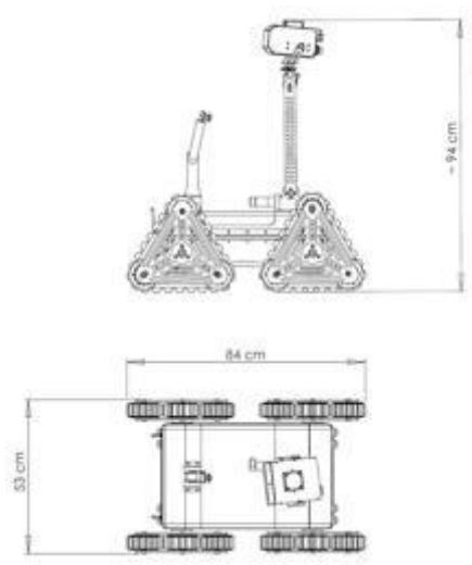
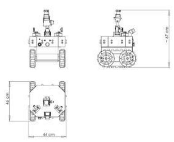
This robot is steered at maximum speed of 1.5 m/s using a pair of velocity-controlled 200 W brushless DC motors while two highly accurate position-controlled 200 W brushless DC motors rotate its triangular frames. Fig. 7 illustrates its overall dimensions.
BETA
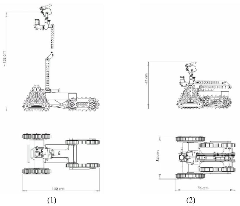
As it is shown in Fig. 8, the rear triangular locomotion modules of our default TTW based platform (e.g. ALPHA) is replaced by a pair of flippers in BETA. These flippers can rotate continuously to extend the effective length of drivetrain or to increase the ground clearance. Length of flippers and Center of Mass (CM) in BETA are set so that the flippers can move up robot's entire body. This helps to detect those victims located in higher than 132 cm from the floor.
DELTA
DELTA (Fig. 9) is a fully autonomous mobile robot which operates only in yellow arena. It has simple Two-Tracked drivetrain with rather small footprint. Two highly efficient velocity-controlled 120 W brushless DC motors powers it to steer in maximum speed of 1.2 m/s.
9. Other Mechanisms
(No text content - section contains subsections only)
Power Management System
Our robots utilize a custom designed power management system for remote supervisory control (e.g. switching devices on/off, voltage-current monitoring and limiting). The power manager is the only device that a user can directly turn it on/off. When it booted up, it follows a step by step procedure to turn on and test the required devices to be wirelessly connected to the OCU (i.e. Ethernet switch and Access Point) and if anything goes wrong, it begins blinking an LED and alarming.
Once the wireless connection is established, the power management system waits for operator's commands to turn on/off any requested onboard device even the industrial computer. This is a useful capability especially when there is no direct access to a robot that may commonly happen in real USAR missions.
Manipulator's Orientation Correction
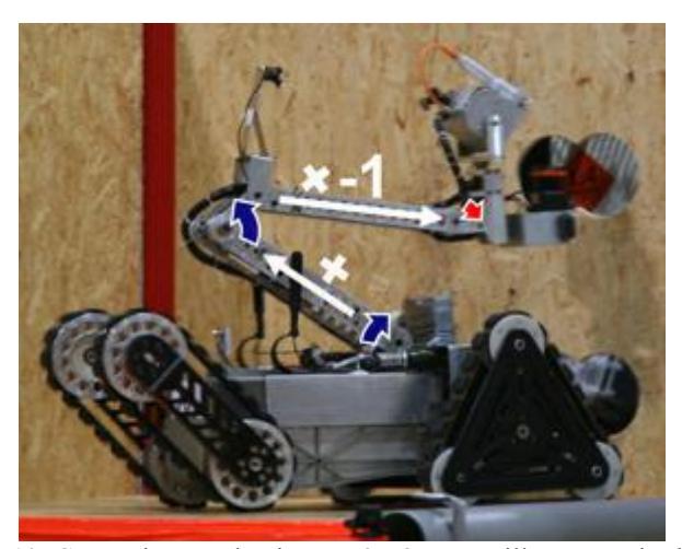
Almost all sensors of BETA are placed on its surveillance manipulator. The end effector of this 2DOF manipulator contains a pan/tilting Victim Detection Package (VDP) and a roll/pitching laser stabilizer servo mechanism. The end effector is also connected to an orientation correction mechanism to stay horizontal in robot's frame of reference. This correction mechanism is actually a combination of two parallelogram four-bar linkages with flexible links and applies a function of rotations of manipulator's joints to the end effector (Fig. 10). This additional feature gives much better third person view over the robot in any arbitrary configuration of the manipulator.
Virtual Inspection
We are building an HMD based augmented reality system in AVA strategic alliance to guide people in pre-defined locations (e.g. museums). Our aim is to develop this system to provide first responders with crucial information for safely inspecting collapsed buildings that are explored by robots. As first step, we will illustrate virtually traversing within 3D mapped arena with an aid of HMD.
10. Team Training for Operation (Human Factors)
A typical computer user without any background of robotics can control our robots after half an hour of familiarization but, a five-hour train-and-practice course is required to perform a simulated USAR mission. We have learned several people with diverse social positions to control our robots and their feedbacks are used to improve HRI quality (Fig. 11)
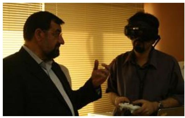
Our GUI automatically saves all video streams sent to the OCU. This simple, useful feature lets us to analyze operator's performance.
Of course, our selected operator spends considerably more time for practicing in the USAR test arena at our laboratory to achieve the best possible result in the competitions. It should also be taken into account that not using our HMD is strongly recommended to people suffering from hurt disorders, high blood pressure or eye diseases and who are under 15 years age.
11. Possibility for Practical Application to Real Disaster Site
Having a real working rescue robot is a highly motivating goal and we are taking our first steps towards this high goal of rescuing human lives.
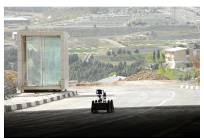
Among aforementioned platforms, ALPHA has been evaluated in several urban and suburban rough terrains for tele-operated land-mine detection (Fig. 12). Besides ALPHA, we have also designed a hydromotor-powered robot for our sponsor, ISOP to be used in Unexploded Ordnance (UXO) gathering operations. This platform is now being tested and modified onsite in south-west of Iran.
12. System Cost
The following tables list approximate cost of our system.
Table 2. Price list of a typical platform
| Device | Company | Model | QTY | Unit Price (USD) |
|---|---|---|---|---|
| Mech. components | T. Khoozestan | 1 | 8000 | |
| Gearhead DC motor | Maxon | RE/EC/EC Power max | 4 | 392 |
| Motor driver | Maxon | EPOSE 70/10 | 4 | 845 |
| Control board | Takin robotics | 1 | 250 | |
| Power manager | Takin robotics | 1 | 200 | |
| Ethernet switch | PLANNET | SW802 | 1 | 20 |
| Access point | PLANNET | WDAP-2000PE | 1 | 120 |
| Antenna | PLANNET | ANT/OM5A | 2 | 13 |
| Industrial computer | Advantech | PCM4380 | 1 | 1,050 |
| Video server | Moxa | VPort 351 | 2 | 555 |
| Camera (wide) | Telecom | 2 | 32 | |
| Battery | Kinetic | Li-Poly | 1 | 370 |
| Battery charger | Thunder Power | TP-1010C | 1 | 194 |
| Other electronics | 50 | |||
| Total Price 16,402 ±1% USD |
Table 3. Price list of sensor payload
| Device | Company | Model | QTY | Unit Price (USD) |
|---|---|---|---|---|
| LRF | Hokuyo | UTM-30LX | 1 | 5,590 |
| LRF | Hokuyo | URG-04LX | 1 | 2,375 |
| IMU | Xsens | MTi | 1 | 2,550 |
| IMU | MicroStrain | 3DMGX1 | 1 | 1495 |
| Stereo vision | Videre | STOC-6cm | 1 | 1520 |
| Ultrasonic ranger | Devantech | SRF08 | 12 | 64 |
| CO2 sensor | Vaisala | GMM | 1 | 925 |
| Temperature sensor | Devantech | TPA81 | 2 | 112 |
| Thermal camera | Ann Arbor Sensor system | AXT100 | 1 | 5995 |
| Camera | Telecom | 2 | 32 | |
| Microphone | 1 | 8 | ||
| Total Price 21,514 ±0.5% USD |
Table 4. Price list of OCU
| Device | Company | Model | QTY | Unit Price (USD) |
|---|---|---|---|---|
| Laptop | Lenovo | Thinkpad X200 | 2 | 1120 |
| Ethernet switch | PLANNET | SW802 | 1 | 20 |
| Access point | PLANNET | WDAP-2000PE | 1 | 120 |
| Antenna | PLANNET | ANT/OM5A | 2 | 13 |
| DC-DC converter | Takin robotics | 1 | 30 | |
| Battery | 12V Sealed acid | 1 | 20 | |
| Gamepad | Xbox | Xbox 360 | 1 | 48 |
| HMD | Cybermind | Visette45ST SXGA + Head Tracker | 1 | 15,200 |
| Aluminum case | 1 | 420 | ||
| Total Price 187,124 ±0.5% USD |
13. Lessons Learned
Award winning teams of RC RRL may (or may not) apply the most cutting edge technologies and innovative ideas but, they certainly are the best prepared teams in terms of device and team working. In other words, they well know how to use their available resources in more efficient way. This cannot be achieved without having team strategy and permanent practices.
13.1. Team Strategy
The team CASualty (Australia) in RC09 is a good example of a team with successful strategy. They managed to win three best in class awards using two robots. Since the results of preliminary round have significant effect on the best of class out-comes, teams should decide which category they are going to focus on. Furthermore, an exact plan of what is expected and what every member should do during each mission will be helpful.
13.2. Autonomy with Mobility
From a quantitative point of view, results of RC09 indicate that nearly no team was successful in yellow arena. For example, the best semifinalist team in this area (MRL) could only find four victims during semifinal round (Fig. 13). This means that less than 34% of victims trapped in yellow arena and 9% of all victims were found by an autonomous.
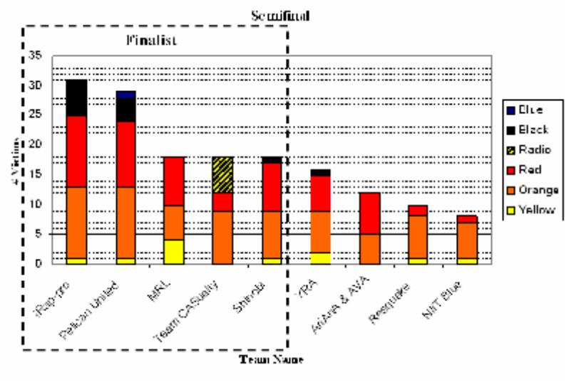
Apart from efficiency and robustness of applied algorithms, almost all autonomous robots suffered from inefficient mobility and placement of victim detection sensors.
On the other side, the team CASualty could score six victims in radio dropout zone and accomplished 100% of the assigned tasks in this region. Their robot was able to autonomously pass steep ramps and timbers located in orange and radio dropout zones. Considering the new rules, a number of improvements in mobility of autonomous robots and autonomy of high mobility robots are required.
13.3. Search Time
In an RRL USAR mission, teams have specific time to setup their robots, find victims and identify them. Therefore, one may identify more victims if he/she can shorten required time for the abovementioned items.
Since autonomous robots identify less than 10% of all victims, teams should have more efficient strategy for their tele-operated robots. In this order, we introduce an implicit function, the Search Time, to evaluate performance of a team of autonomous and tele-operated rescue robots. The Search Time ($t_S$) is defined as (1) and indicates the available time in which an operator should drive a tele-operated robot next to a new victim.
$$t_s = \frac{t_M - t_b - V_{Total} \times t_i}{V_{Tele}} \tag{1}$$
Here $t_M$, $t_b$, $V_{Total}$, $t_i$ and $V_{Tele}$ indicate mission duration, start up time, number of found victims, average time that is needed to identify a victim and number of victims detected by tele-operated robots respectively.
Apparently, the Search Time $(t_s)$ should be decreased if it is expected to find more victims by tele-operated robots $(V_{Tele})$ in a given time. But it may seem a paradox that decreasing victim identification time $(t_i)$ will lead to increasing $V_{Tele}$ or describing $t_s$. To accomplish our statistical analysis, we recorded operators' performance of all semi-finalist teams in RC09 (Fig. 14).
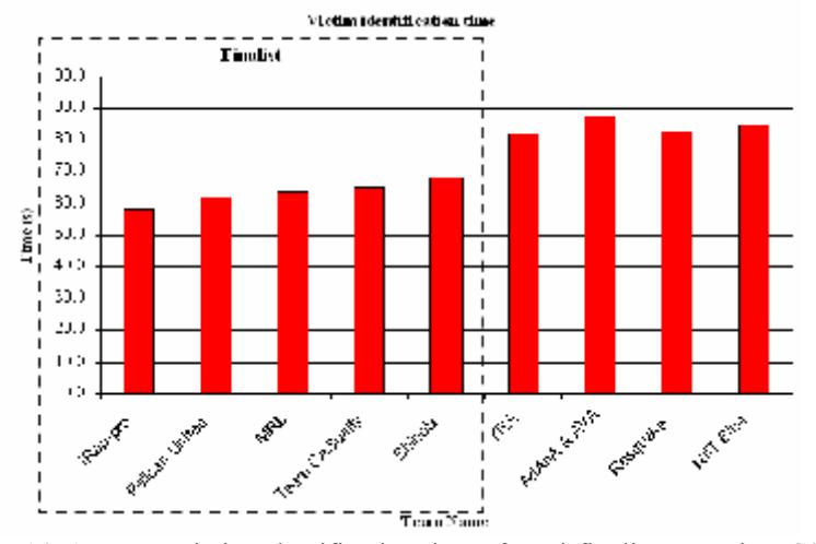
It should be mentioned that we measured identification time since a robot stops in victim pallet till it starts moving.
As it is shown in Fig. 14, our operator spent about 1.5 times more than finalist teams to identify a victim. At the time being, we are applying several optimizations in our team to reduce both Identification and Search times.
13.3. Maneuverability of Manipulators
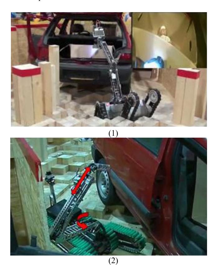
In RC09 only two semifinalist teams, AriAnA & AVA with iRap-Pro had equipped their robots with such manipulators that could detect victims placed in more than one meter height. But, the Thai robots had significantly faster manipulation as a result of two extra DOF's in their identical robotic arms (Fig. 15). The yaw and prismatic joints of this manipulator not only speeded up the operation, but also made it possible to reach to the target position in confined places.
At the time of writing this document, we are designing a new manipulator to possess the aforementioned capabilities.
Appendix
Qualification Videos (YouTube): http://www.youtube.com/watch?v=iNBSpAXKmqY http://www.youtube.com/watch?v=K8dKR98Oc-g
Qualification Videos (Download links): http://robotics.isop-co.com/movie/trailer.mpg http://robotics.isop-co.com/movie/P3+mapping.wmv
References
- Player/Stage: http://playerstage.sourceforge.net
- SLAM6D: http://openslam.org/slam6d.html
- Murphy, R.R.: Activities of the Rescue Robots at the World Trade Center from 11–21 September 2001. IEEE Robotics & Automation Magazine (2004) 50–61
- Gerkey, B. P., Vaughan, R. T., Howard A.: The Player/Stage Project: Tools for Multi-Robot and Distributed Sensor Systems. International Conference on Advanced Robotics (ICAR 2003), Coimbra Portugal (2003) 317–323
- Yamauchi, B.: A frontier-based approach for autonomous exploration. IEEE International Symposium on Computational Intelligence in Robotics and Automation (1997)
- Johnson: Don'ts and Do's for Software Developers and Web Designers. San Francisco, Morgan-Kaufmann Publishers (2000)
- Adams, J. A.: Critical Considerations for Human-Robot Interface Development, AAAI Fall Symposium, Human Robot Interaction Technical Report (2002)
- Keyes, B.: EVOLUTION OF A TELEPRESENCE ROBOT INTERFACE. Final thesis for M.Sc. degree. Department of Computer Science. University of Massachusetts Lowell (2007)
- GMapping: http://www.openslam.org/gmapping.html
- Grisetti, G., Stachniss, C., Burgard, W.: Improving grid-based SLAM with raoblackwellized particle filters by adaptive proposals and selective resampling, ICRA05 (2005)
- Balaguer, B., Carpin, S., Balakirsky, S.: Towards Quantitative Comparisons of Robot Algorithms: Experiences with SLAM in Simulation and Real World Systems. IROS workshop (2007)
- Lingemann, K., Neuchter, A., Surmann, H., Hertzberg. J.:6D SLAM Preliminary Report on closing the loop in Six Dimensions. In Proc. of the 5th IFAC Symposium on Intelligent Autonomous Vehicles (2004)
- Censi, A.: An ICP variant using a point-to-line metric. ICRA08 (2008)
- Pellenz, J.: Rescue robot sensor design: An active sensing approach. Fourth International Workshop on Synthetic Simulation and Robotics to Mitigate Earthquake Disaster (2007)
- Wulf, O., Wagner, B.: FAST 3D SCANNING METHODS FOR LASER MEASUREMENT SYSTEMS, Institute for Systems Engineering, University of Hannover, Germany
- Konolige, K.: The Small Vision System. http://www.ai.sri.com/~konolige (2006)
- Pellenz, J.: TDP of resko@UniKoblenz (Germany). RoboCup Rescue Robot League (2008)
- Soltanzadeh, A. H., Chitsazan, A.: Mobile Robot locomotion based on Tracked Triangular Wheel mechanism. Final thesis for B.Sc. degree, Mechanical Engineering Department. IAUCTB (2006)
- Mahbadi, H., Soltanzadeh, A. H., Emami, M., Soltanzadeh, M.: TDP of AriAnA (Iran). RoboCup Rescue Robot League (2009)