RoboCupRescue 2010 – Rescue Robots IXNAMIKI (Mexico)
Américo Lorenzana, Alfonso López, Benjamín López, Rodrigo González, Alan Torres, Ricardo Rangel
Mecatrónica y Control de Sistemas – Mobile Robotics Group, Universidad Panamericana Aguascalientes, Mexico, 20290
Abstract This paper presents IXNAMIKI, the first prototype of rescue robot developed at the MCS Mobile Robotics Group to compete at Robocup 2010. IXNAMIKI consists of a track wheel type structure. With double front flippers, it is capable of moving, climbing and collapsing rough terrain. IXNAMIKI also encompasses a 6-joint mechanical arm which can be deployed not only for surveillance from the top view but also for easier and faster access to the victims. A video camera and a set of sensors are set up at the tip of the mechanical arm to aid the operator during rescue decision making. The mapping techniques included in this prototype take advantage of a 2D real-time laser scanning.
Introduction
The RoboCup Rescue competition aims at boosting research in robots and infrastructure able to help in real rescue missions. The task is to find and report victims in areas of different grades of roughness, which are for the competition purposes currently indoors. It challenges the mobility of the mechanical platforms as well as the autonomy of their control and sensor interpretation.
For the 2010 competition, the MCS Mobile robotics group proposes the prototype IXNAMIKI (which means "people finder" in nahuatl, the language of ancient Aztecs).
IXNAMIKI is a robot capable of traversing, sensing and mapping a complex and unknown terrain. It is small and lightweight for maximum maneuverability. It offers all-terrain capabilities using two sets of independent flippers to move and climb over obstacles.
It requires one operator. However, the operator is aided in the maneuvering and rescue decision making by the robot. All the other functionality is fully automatic i.e. image acquisition, sensing, and mapping.
This paper presents a technical overview of IXNAMIKI: design, main modules and first prototype.
1. Team Members and Their Contributions
Américo Lorenzana Team captain and manufacturing
Alfonso López Sensors
Benjamín López Manufacturing and sponsorship Rodrigo González Programming and communications
Alan Torres CAD and programming
Ricardo Rangel Manufacturing Guillermo Medina Team advisor Dr. Ramiro Velázquez Faculty advisor
2. Operator Station Set-up and Break-Down (10 minutes)
Our system consists of a compact (64 x 59 x 15 cm), lightweight (40 kg) robot that is able to work autonomously or can be remote controlled via a laptop wireless LAN. The whole control equipment easily fits into a standard backpack and IXNAMIKI can be carried by 2 persons. So, to start/end a mission, a minimum of 3 people are needed to carry both robot and control equipment.
3. Communications
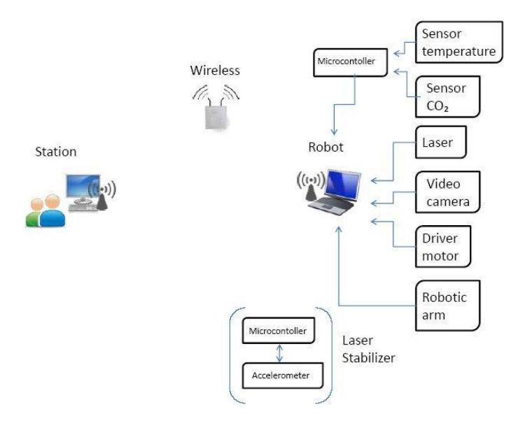
Our main design concept is simple but highly effective and reliable. The block diagram of the rescue robot IXNAMIKI is shown in Fig. 1.
Here, the robot encompasses a set of key items such as a temperature sensor, a CO2 sensor, a video camera, a laser, the motor driver and the mechanical arm. All of these are controlled by a single on-boar computer and either plugged directly to the computer or previously conditioned through a micro-controller. Information obtained from these sensors is sent to the operator via a wireless LAN network. At the remote station, the operator is able to take decisions and send back to the robot controlling commands for both robot and mechanical arm. For the laser, the mapping sensor, an accelerometer is included as stabilizer. This stabilization is processed locally at the robot.
Our system uses a communication frequency of 2.4GHz, no special channel or band is needed, and adheres to 802.11g standards.
Rescue Robot League — Frequency and Communication Specifications
| Rescue Robot League | ||||
|---|---|---|---|---|
| IXNAMIKI (Mexico) | ||||
| Frequency | Channel/Band | Power (mW) | ||
| 2.4 GHz - 802.11b/g | any | - |
4. Control Method and Human-Robot Interface
IXNAMIKI is both autonomous and remotely controlled by the operating station via keyboard and joystick. Autonomous navigation relies on the on-board laser sensor and remote control relies on wireless communication with the command center.
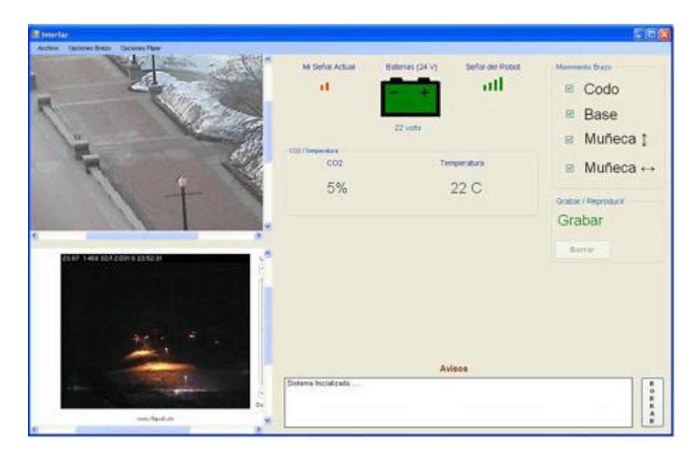
The command center encompasses 2 main elements: laptop computer and a joystick. In the laptop computer a human computer interface is running to display the key features of the rescue mission such as:
- Live video image: Video coming from the on-board camera. The operator will be monitoring the live feed and adding details to the map. For example: location of victim detected
- Map being generated: Map will be generated by the 2D laser scanning
- Information from other sensors: Other sensor information will also be displayed. For example: temperature, CO2, etc.
Fig. 2 shows a snapshot of the user interface.
5. Map generation/printing
Map generation method in IXNAMIKI is based on the operator assessment in conjunction with the collected data, which enables the operator to locate and register different object such as victims, stairs, walls and hazards. The robot has a 2D laser beam, a video camera, a temperature sensor and a C02 sensor that provide enough information to operator station.
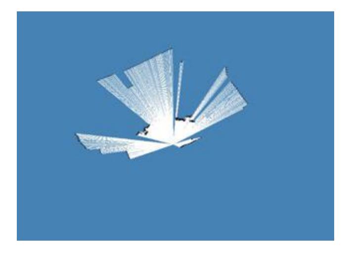
A laser-beam will be projected onto an object and the resulting distance is reconstructed in the user interface at the operator station (Fig. 3).
6. Sensors for Navigation and Localization
IXNAMIKI relies on 2 items for navigation and localization:
- Wheel encoders: To measure the translational and rotational speed of IXNAMIKI, all wheels are equipped with incremental optical encoders. This odometer data is used especially for indoor navigation, but due to the inaccuracy additional feedback from other sensors is needed.
- Laser scanner: The Hokuyo URG04-LX laser scanner covers an arc of 240° with 0.36° resolution per scan. It has a maximum range of 4m and a maximum sample rate of 10Hz. The scanner unit is stabilized with an accelerometer to balance the effects of uneven surfaces.
7. Sensors for Victim Identification
Victim detection will be approached from several sensors:
- Video camera: The video camera located at the tip of the mechanical arm is being used to capture real-time video. Video processing is done on the base station to detect any victim or motion.
- Thermal sensor to detect victims autonomously by their body heat. The mechanical arm moves the thermal sensor. The sensors data is sent to the base station where the information is processed.
- CO2 sensor to confirm the deal/live status of a victim found.
8. Robot Locomotion
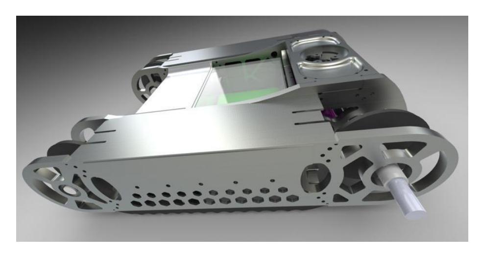
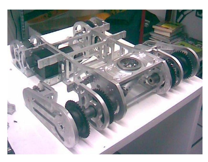
Rescue robot IXNAMIKI is a tracked wheel vehicle. It is relatively lightweight (about 40 kg.) and have small dimenssions (64 x 59 x 15 cm). It is quite active and fast in unstructured environments and it also performs well on uneven terrain.
Tracked wheels are very popular in the RoboCup rescue league, for example in the robots of Team Freiburg, Robhaz, Casualty, IRL and IUB [1-5]. The track wheel robots which mentioned above are variety designs. Each design has different good points. In this robot, the tracks which use for the locomotion are double tracks (wheel track and flipper track). They are very useful for climbing over the pile of collapse.
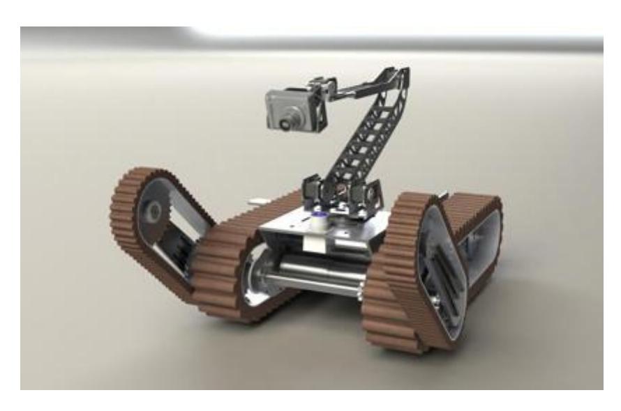
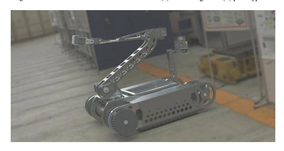
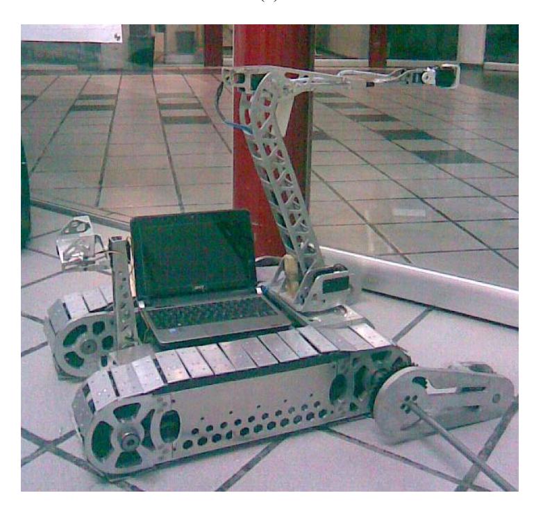
Fig.4 (a) shows IXNAMIKI conceptual design while fig.4 (b) shows the first prototype developed.
9. Other Mechanisms
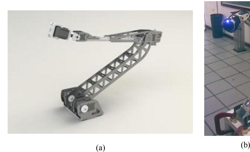
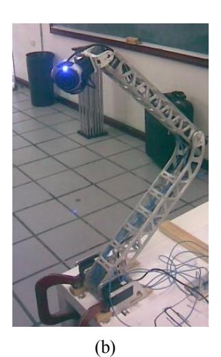
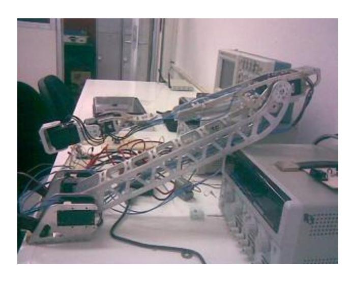
IXNAMIKI includes a mechanical arm. It helps the robot to explore in many ways such as, from high level, going to narrow space and able to get vital signs of victims easier and faster. Fig. 5 shows both conceptual design and prototype of the mechanical arm which has 6 degrees of freedom. Because the pay load at the tip of arm is small and the arm structure weight is not much, servo motor with gear set still can regulate the joint angle quite well.
10. Team Training for Operation (Human Factors)
- Practice with locomotion controls (joystick)
- Interpretation and navigation using streaming video
11. System Cost
The system cost is broken down into three main categories: mechanics, electronics, and other components.
11.1 Mechanics
The mechanical components of IXNAMIKI.
Mechanics Cost Breakdown
| Part name | Quantity | Cost (USD) |
|---|---|---|
| Anaheim Motors | 3 | $1,080 |
| Dynamixel RX-64 | 3 | $819 |
| Dynamixel AX-12 | 2 | $100 |
| Chains and mechanisms | $1,923 | |
| Aluminum and other materials | $600 | |
| TOTAL | $4,522 |
11.2 Electronics
The electronic components of IXNAMIKI.
Electronics Cost Breakdown
| Part name | Quantity | Cost (USD) |
|---|---|---|
| Laser HOKUYO URG-LX04 | 1 | $3,900 |
| Driver RoboteQ AX-3500 | 1 | $600 |
| Driver RoboteQ AX-1500 | 1 | $400 |
| Sensors | $600 | |
| Batteries | 2 | $150 |
| TOTAL | $5,650 |
11.3 Total
The complete cost summary for IXNAMIKI.
System Cost Total
| Cost | |
|---|---|
| Mechanics | $4,522 |
| Electronics | $5,650 |
| Others | $622 |
| TOTAL | $10,794 |
References
- A. Kleiner, B. Steder, C. Dornhege, D. Meyer-Delius, J. Prediger, J. Stueckler, K. Glogowski, M. Thurner, M. Luber, M. Schnell, R. Kuemmerle, T. Burk, T. Brauer, and B. Nebel, "Robocup rescue – robot league team rescuerobots freiburg (germany)," in RoboCup 2005: Robot Soccer World Cup IX, ser. Lecture Notes in Artificial Intelligence (LNAI), I. Noda, A. Jacoff, A. Bredenfeld, and Y. Takahashi, Eds. Springer, 2006.
- W. Lee, S. Kang, S. Lee, and C. Park, " Robocuprescue- robot league team ROBHAZ-DT3 (south Korea)," in RoboCup 2005: Robot Soccer World Cup IX, ser. Lecture Notes in Artificial Intelligence (LNAI), I. Noda, A. Jacoff, A. Bredenfeld, and Y. Takahashi, Eds. Springer, 2006.
- M. W. Kadous, S. Kodagoda, J. Paxman, M. Ryan, C. Sammut, R. Sheh, J. V. Miro, and J. Zaitseff, " Robocuprescue- robot league team CASualty (Australia)," in RoboCup 2005: Robot Soccer World Cup IX, ser. Lecture Notes in Artificial Intelligence (LNAI), I. Noda, A. Jacoff, A. Bredenfeld, and Y. Takahashi, Eds. Springer, 2006.
- T. Tsubouchi and A. Tanaka, " Robocuprescue- robot league team Intelligent Robot Laboratory (Japan)," in RoboCup 2005: Robot Soccer World Cup IX, ser. Lecture Notes in Artificial Intelligence (LNAI), I. Noda, A. Jacoff, A. Bredenfeld, and Y. Takahashi, Eds. Springer, 2006.
- A. Birk, K. Pathak, S. Schwertfeger and W. Chonnaparamutt, "The IUB Rugbot: an intelligent, rugged mobile robot for search and rescue operations", International Workshop on Safety, Security, and Rescue Robotics (SSRR), IEEE Press, 2006.