RoboCupRescue 2010 - Robot League Team SEU-RedSun (China)
Jian Wang, Yingzi Tan, Yingqiu Xu, Xiaoli Xu, Jie Rong, Chunlu Jiang
School of automation, Southeast University; School of Mechanical Engineering, Southeast University
Abstract This paper describes the SEU-RedSun rescue robot team , which will participate RoboCup 2010 with two robots. One robot is four-wheel independent driving construction, which is easy over the incline and low step terrain, and is easy to control. It focuses on implement the autonomous function. The other is a tracked robot with four flippers; it excels on rough terrain with tele-operation. Both robots are able to create map automatically, and share the information each other.
Introduction
SEU-RedSun rescue robot team was found in 2008, participated in China open 2009, original from virtual robot competition SEU-RedSun team, which won the champion in RoboCup 2008 Suzhou, China and was awarded 2nd place in RoboCup 2009 Glaz, Austria.
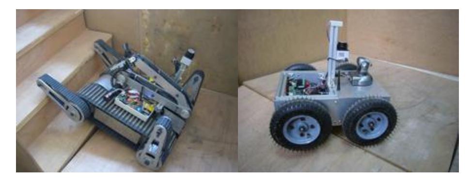
Fig 1 shows our robots: the left one is the robot awarded $2^{nd}$ place in China Open 2009; the right one is the autonomous robot with four-wheel independent driving construction.
1. Team Members and Their Contributions
[Table below]
Team Members and Their Contributions
| • | Name | Role |
|---|---|---|
| • | Yingqiu Xu | Advisor |
| • | Yingzi Tan | Advisor |
| • | Ruiming Qian | Advisor |
| • | Yijun Zhou | Advisor |
| • | Jie Rong | Mechanical design |
| • | Yueliang Dai | Mechanical design |
| • | Qinglong Liu | Mechanical design |
| • | Jian Wang | Controller development |
| • | Peng Sun | Controller development |
| • | HeChang Rao | Controller development |
| • | Kai Wang | Controller development |
| • | ChunLu Jiang | Software development |
| • | Si Chen | Software development |
2. Operator Station Set-up and Break-Down (10 minutes)
We use only one notebook PC for the operation, so our main devices are only one robot and one notebook PC, therefore the operation is plug and play and the Set-up and Break-Down operation will be quick in a similar way.
3. Communications
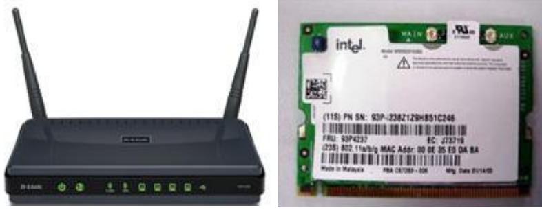
The robots are configured with wireless network with 802.11a/5GHz. Both robots only use one wireless communication channel. We use dual band router and miniPCI wireless board(See Fig.2). Considering the reliability of wireless communication in practice, we reduce the dependence on wireless, the autonomous robot can normally run in drop out zone because of fully on board data process control, the tele-operative robot can work in reduced functionality mode.
Communication channels
| Frequency | Channel/Band | Power (mW) |
|---|---|---|
| 5.0 GHz - 802.11a | 1 channel/Selectable | 100 |
4. Control Method and Human-Robot Interface
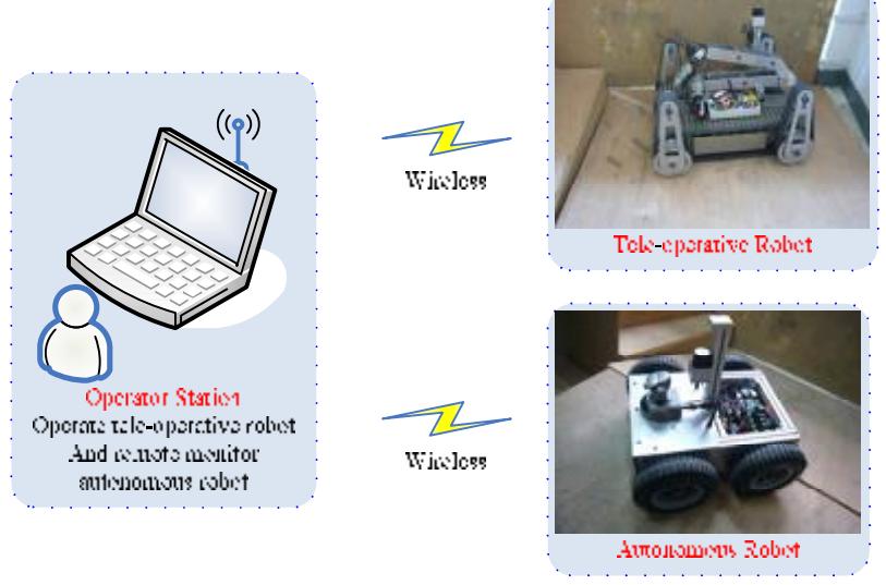
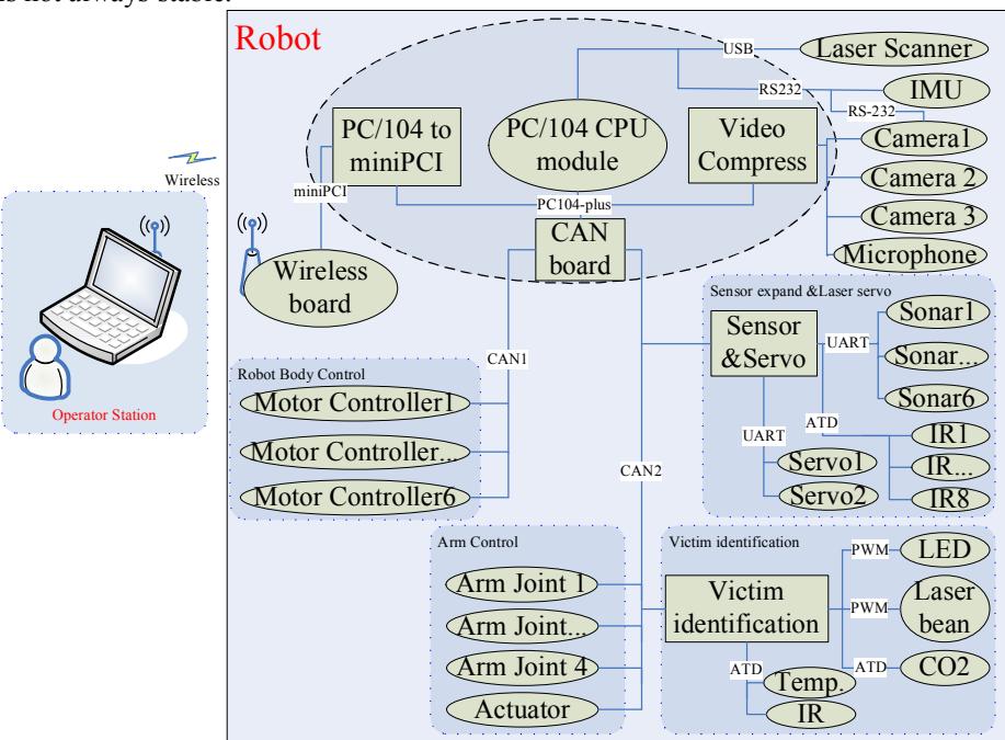
According to the different functionality, each robot use independently control method. On the autonomous robot, we use MCU + Notebook PC construction. And on the tele-operative robot, we use PC/104+ construction to control the flexible mechanism. Meanwhile it is easy to update step by step, because each module is independent, the common function control module, such as CO2, temperature, laser 2 degree servo module, can work on both robot platforms by no modification due to use CAN bus.(See Fig.3)
4.1 Autonomous robot
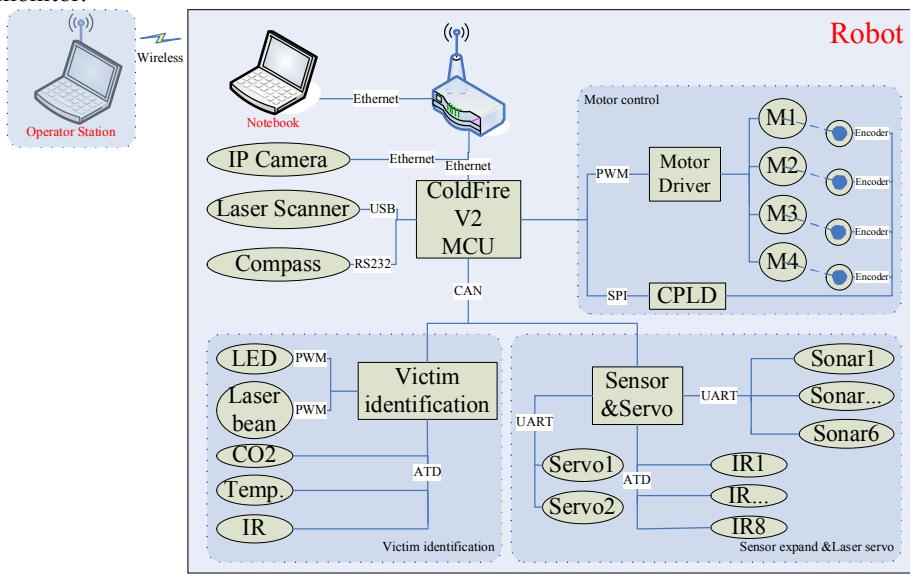
Fig.4 describes the autonomous robot construction. The robot is equipped with notebook, the ColdFire MCU ( the main controller on the robot for robot motion control), sensor data acquirement (including laser scanner, electronic compass, CO2, temperature, sonar and IR distance sensor). For decode the rotate encoder pulse, one CPLD is used. The video and audio stream is obtained by PTZ IP camera, and direct transmits to notebook through Ethernet. The operator station is option as a remote monitor.
4.2 Tele-operative robot
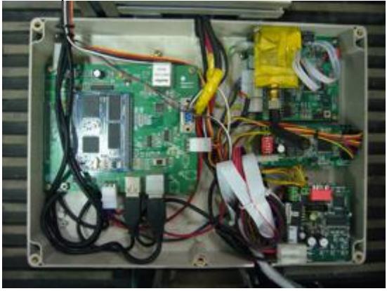
In the old version, we use ARM as the main controller on the robot (Fig.5), this way can obtain compact construction and we can design a system as we want. And it works well as we expect. But it is difficult to update step by step because of system integrated on the single board. Of course, we found it is difficult to compress video and process on the ARM processor.
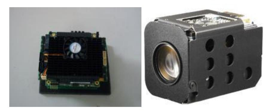
On the new version, we use PC/104 embedded PC as the main control on the robot(Fig.6), as a common local bus standard, it is easy to implement each function independently, meanwhile, for enough performance of CPU, the robot can run in drop-out zone with reduced function. Because we found the wireless communication is not always stable.
4.3 Autonomous and Human-Robot Interface
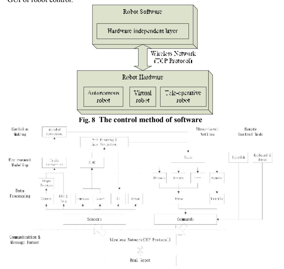
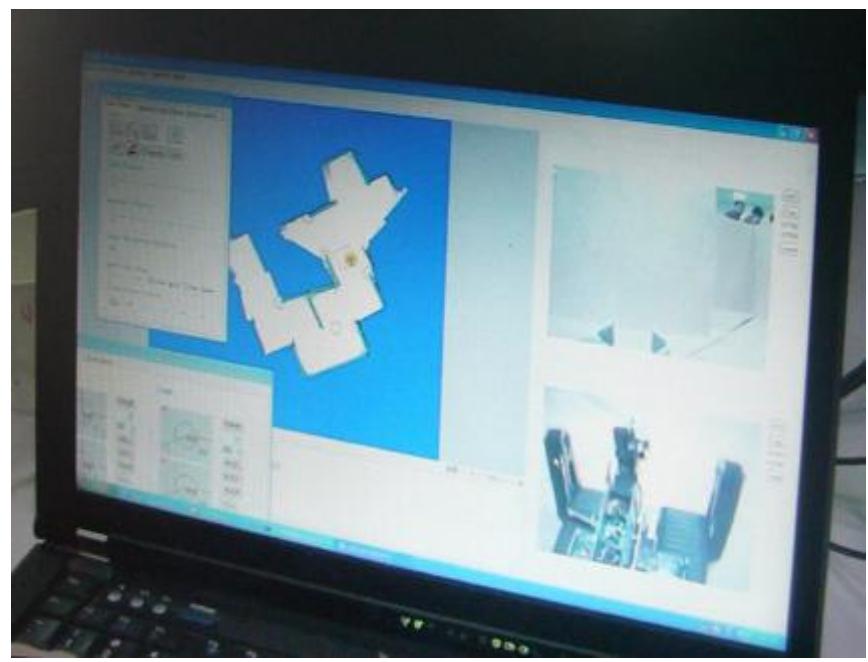
There are some effective ways on localization, navigation, and multi-robot cooperation, which are tested in the simulation environment. We focus on complement this way on our real robot, meanwhile, find the different between real world and the simulation environment in detail (the unconfirmed factor is more than the simulation environment). However, in the early phase, it is effective to use UARSim to develop the software framework and new method first test, and it is not enough to test the method which used on the real robot, so in the new vision, we still use UARSim in the early phase to develop the software when the hardware of the robot is in update, so in the framework of the software, there is a hardwareindependent layer, to reduce the effect about different hardware framework, which is shown on Fig.8. The flow chart of the software is shown on Fig.9. Fig.10 shows the GUI of robot control.
5. Map generation/printing
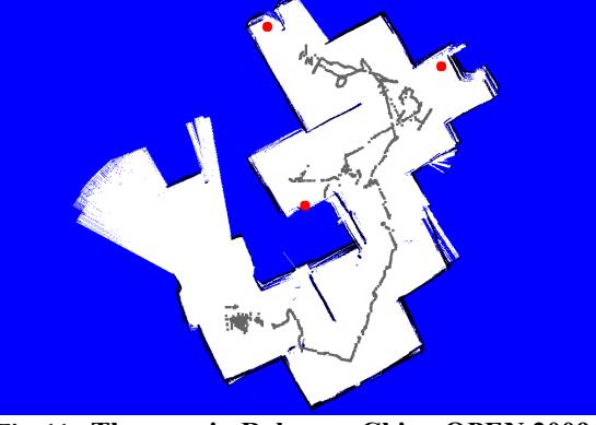
To achieve an accurate geo-referenced map, the robot should know its position synchronously and exactly during the exploration, while the position data got from the odometry senor or inertial navigation sensor is always with a large error. Laser range scanners can deliver highly accurate measurements, and a position estimated based on scan matching is impressive for indoor environments. Fig.11 shows the map in China open 2009.
6. Sensors for Navigation and Localization
In order to manipulate the robot in an unknown environment, we use several digital sensors to gather information about the environment. The robot is equipped with the following sensors for localization and navigation:
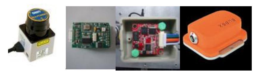
- Scanning Laser Range Finder (URG-04LX) is used to provide a precise measurement [4] .
- Digital Compass Module (HMR 3300) measures the roll, pitch and heading direction of the robot [5] .
- Digital Compass Module (OS5000S) is same to HMR3300,but the output data frequency is configurable, it is easy to sync to other sensor ouput.
- MTi xsens AHRS, it is good in dynamical on measuring the roll, pitch and heading.
- Odometry, it use the rotate output to compute the head and distance. It is worth in the skipped environment, but it one option to help localization and navigation. The sensors are shown in Fig.12.
7. Sensors for Victim Identification
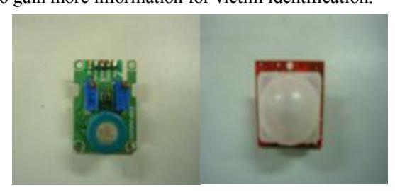
We use a camera fixed on the arm of the robot for identifying and localizing victims. The video streams with picture data are transferred into the operator interface. Furthermore, the microphone, temperature and CO$_{2}$ sensors are equipped on the end of the robot arm to gain more information for victim identification.
8. Robot Locomotion
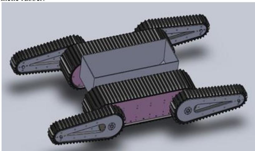
The robot is the same as shown in the Fig 14. The drive system of the robot use conveyer belt which can be used on different types of terrain. This robot includes several parts: two movement modules for the left and right and two pairs of flipper (front and back). Each pair of flipper can rotated 360 degree and work independently of each other. Through compare and research, we find that this structure is better for the disaster situation.
In order to step up the bottom of the body, the body and movement module are entirely separated except several linkers. Therefore, three DC motors are hided in the body of movement module, one for the movement of belt and the others for the rotation of flippers. Most of the structure is made of Aluminum and the belt is made of synthetic rubber.
9. Other Mechanisms
Modular design approach is used for the robot. In that way, the robot can be divided into several modules, left and right main track modules, two pair of flipper, body control section and mechanical hand. Every module can be easy removal and assembly. When a certain part comes across with a problem, we can quickly get to replace the module in a short time, so the robot can play a greater rescue effect.
10. Team Training for Operation (Human Factors)
The operator should be familiar with the structure and the function of the GUI and be able to immediately understand the data of all sensors showed in the GUI. As the operator, he also needs to drive the robot remotely according to the video stream of the camera and the distance of the obstacles scanned by laser.
11. Possibility for Practical Application to Real Disaster Site
We yet have no practical experience with real disaster sites. However, we consider the practical application when design the robot, such as compact mechanism, modular design, less operator station setup time.
12. System Cost
[Tables below]
autonomous robot cost
| Part Name | Quantity | Price |
|---|---|---|
| motor + Gearhead + Encoder | 4 | ¥3,000 |
| Other mechanical parts and manufacture | ¥3,000 | |
| Scanning Laser Range Finder(URG-04LX) | 1 | ¥19,000 |
| Digital Compass Module (OS5000S) | 1 | ¥3,000 |
| Wireless router (DIR-628) | 1 | ¥1,000 |
| Laptop | 2 | ¥30,000 |
| Laser servo controller | 2 | ¥2,000 |
| IP Camera(FSC1010) | 1 | ¥2,800 |
| PCB | ¥2,000 | |
| Other electrical parts | ¥2,000 | |
| Battery | 2 | ¥1,000 |
| Total | ¥68,800 |
tele-operative robot cost
| Part Name | Quantity | Price |
|---|---|---|
| Maxon motor (RE36) + Gearhead + Encoder | 4 | ¥36,000 |
| Maxon motor (RE40) + Gearhead + Encoder | 2 | ¥20,000 |
| Other mechanical parts and manufacture | ¥60,000 | |
| PC104-plus computer | 1 | ¥15,000 |
| Scanning Laser Range Finder(URG-04LX) | 1 | ¥19,000 |
| MTi AHRS (MTi-28 A53 G35) | 1 | ¥18,000 |
| Laptop | 1 | ¥15,000 |
| Camera | 3 | ¥5,000 |
| Laser servo controller | 2 | ¥2,000 |
| PCB | ¥3,000 | |
| Other electrical parts | ¥5,000 | |
| Battery | 2 | ¥4,000 |
| Total | ¥202,000 |
13. Lessons Learned
References
- Coste-Maniere, E., Simmons, R.: Architecture, the backbone of robotic systems. Vol. 1. Robotics and Automation (2000) 67-72
- Jonathan H. Connell: A Hybrid Architecture Applied to Robot Navigation. International Conference on Robotics and Automation (1992) 2719-2724
- CAN2.0A: CAN in Automation (CiA), http://www.can-cia.org/fileadmin/cia/specifications/CAN20A.pdf
- Hokuyo: Hokuyo URG-04LX Laser, http://www.acroname.com/robotics/parts/R283-HOKUYO-LASER1.pdf
- Honeywell: Digital compass solutions HMR3200/HMR3300, http://www.magneticsensors.com/datasheets/hmr32003300.pdf
- D-link: dir628 user manual V1.2, ftp://ftp.dlink.com/Gateway/dir628/Manual/dir628_manual_120.zip
- xsens: MTi miniature attitude and heading reference system, http://www.xsens.com/en/general/mti
- Sony: FCB-CX11DP, http://pro.sony.com.cn/productinfo/b2b/isp/12654.htm