RoboCupRescue 2010 - Robot League Team eeeBot (Singapore)
Han Wang, Xian Wang, Reeti Burman
School of EEE Nanyang Technological University
Abstract In this Paper, the main features of the eeeBot Rescue Robot have been described. It is a fully autonomous robot. Contribution of each team member has been specified and details about the control method, sensors used, navigation and localization methods, map generation, robot locomotion, path planning and victim identification methods have been explained. The set of sensors being used enable the system to work effectively and autonomously in a disaster site.
Introduction
In real disaster situations, it is very important for rescue operation to be quick in order to save lives of victims. So it would be quite useful to have autonomous systems which can assist rescue teams to perform rescue operation. The basic aim of the RoboCup Rescue league is to develop such autonomous systems that can effectively work in case of natural calamities like earthquakes that are dangerous for human rescuers while at the same time rescue operation should be fast and accurate. The rescue robot should be able to navigate efficiently in unknown environment without prior knowledge of the site. Autonomy is of great importance in search and rescue robots as human control has its limitations like negligence and inefficiency of operators. At the same time, the rescue robot should be convenient for onsite deployment and modification.
Hence, we've been focusing on developing a reliable autonomous system for real disaster situations. The eeeBot is a four-wheeled autonomous mobile robot suitable for the yellow arena. CO2 gas sensor, thermal camera and optical camera are implemented for victim identification. As the robot moves, the laser scanner senses obstacles in robot's neighbourhood, helps in building a map simultaneously and demonstrating robot's location.
In the following sections, we have provided detailed explanations of our techniques and implementation.
1. Team Members and Their Contributions
• Wang Han Team leader
• Shantanu SinghSingh Saliency detection
• Maruvanda Aiyappa Chengappa Boundary detection • Wang Junling Hand Detection • Tay Zhixiong Body Detection • Mohamed Thalal Mohamed Thoufeek Thermal Detection & Arm Movement Control
• Sun Mouxuan 3D map
• Reeti Burman CO2 detection and SLAM • Wang Xian Thermal Detection and SLAM
• Wang Jiao Motor Drive • Han Aiguo Motor Drive • Li Yang SLAM
• Guo Guibing Laser Sensor and
SLAM
• Yang Qianwen Localisation module • Adrian How Wei Liong Hand Detection • Cham Jun Wei Alan Toshihito Hardware
• Neo Kok Chuan Hardware/Software
• Chia Chiu Kiat Hardware
• DIP group(20 people) Hardware/Software
2. Operator Station Set-up and Break-Down
N/A
3. Communications
N/A
4. Control Method and Human-Robot Interface
This design is a fully autonomous rescue robot with an auxiliary Human-Machine Interface enabling fast field deployment and on field adjusting. This system can be switched to semi-autonomous or manual override mode during debugging, however, in practical field work; this system is always working in fully autonomous mode, with no telecommunication cable or radio remote control channel. Such design decreases its dependency on field conditions, increasing its reliability and robustness.
5. Map generation/printing
This design uses a 3 stage solution to implement odometry sensing, SLAM and path planning; all three of them are based on laser scanner sensing data only, with no encoder on board.
5.1 Odometry sensing
Odometry sensing compares different frames between scans. The laser scanner keeps scanning surrounding obstacles, generating relative maps simultaneously. Without considering the error in scanning, the difference between each scans can be described with a translation and a rotation, which can be depicted with a vector (x, y, Theta). This vector represents the movement of scanner or robot between each scan, that is, the odometry.
However, we do have errors in scan data. Such error can be approximated with Poisson Distribution or discrete Gaussian Distribution. We use a 3-D search space to describe different odometry vectors which is possible in specified movement; different values of element mean different possibilities of certain movement vector. The global maxima point of this search space would represent the most possible vector.
We made use of Distance Transformation in determining space elements, which is a 3 step algorithm. First, apply an odometry vector upon the original scanning map, generating another map that is similar to the map of the following scan to a certain extent. Second, determine distance between key points on transformed map and the skeleton of the following scan at all 8 directions. All distance values are added together to generate value of certain element corresponding to odometry vector. City block distance was used instead of Euler distance to avoid huge amount of computing. The final step is to search and find out the global maxima of search space, whose position denotes the odometry vector of maximum possibility. In light of the Gaussian Distribution of scanning errors, this search can be done with linear search algorithm from a certain start point, which can be determined with raw command values from the motion control module. The 3 steps are carried out simultaneously and repeatedly, estimating odometry vector after executing each motion command.
5.2 SLAM
The odometry sensing stage determines the most possible odometry vector from comparing two adjacent laser scanning maps, while SLAM stage crawl among large amount of simultaneous scanning data and estimated odometry data which is provided by odometry sensing stage to determine more accurate odometry data along with estimated global maps.
The SLAM algorithm used in this design is DP-SLAM 2.0 which was developed by Duke University. DP-SLAM is a kind of inherited particle SLAM algorithm. Input parameters of this algorithm are roughly estimated odometry data and corresponding laser scanner data, while output of the algorithm are low level & high level maps, along with more accurately estimated odometry vectors.
Particle filter SLAM treats dots in laser scan data as particles; higher probability of obstacle means particles with more weight. Particles carry global coordinates and weights and would be added up together to denote a final probability map of obstacles. Detailed implementation of particle filter also requires low weighted particles be filtered out in order to decrease uncertainty. The SLAM algorithm determines odometry vector according to relative movement to estimated map of scanner origin.
Inherited SLAM is a 2 level algorithm. The low level is the basic particle SLAM algorithm, with raw scan data converted to particles. Therefore, particles in low level SLAM contain global coordinate and probability of possible obstacles, generating only regional map with little movement range of robot. However, a high level SLAM is used to generate a more accurate map of environment, which would avoid problems of accumulating error brought by odometry errors. High level SLAM uses particles carrying data from regional maps, which are combined together to generate global maps. Therefore, particles in high level SLAM are mostly used to depict key points in regional maps, while the combining procedures are mostly focused on solving translation, rotation and skew problems at the patch areas.
The final map submitted for printing is adjusted global map, which is generated by high level SLAM. Different colors on map indicate different situations: possible obstacles, clear grounds and undiscovered areas.
5.3 Path planning
Path planning module focuses mostly on 1) make the robot explore undiscovered areas to find obstacles and victims; 2) keep the robot away from known obstacles; 3) make it possible for the robot to reach specified position on the map.
We are using VFH (Vector Field Histogram) method to realize the first two points and A* to realize the last point.
VFH is a kind of obstacle avoiding algorithm, which is improved to provide ability on navigating into the unknowns. VFH uses different values to represent obstacle, clear area and undiscovered area. Different areas can be assigned values according to global map build in SLAM stage. In this solution, obstacles can be assigned 1, clear area can be assigned 0 and undiscovered area can be assigned -1. The algorithm creates a vector field polar histogram with an optimized formula, which is further used to determine the best direction for the robot to travel. In this case, the robot should travel in direction which has lowest histogram value.
A* algorithm is a kind of heuristic static shortest path algorithm, which is used in finding path on pre-determined static map, that is, networks and routines on map should remain the same while time period changes. Such condition is satisfactorily fulfilled in this application. Therefore, after generating the final global map, A* algorithm can be used to navigate back to pre-defined navigation points such as victims or key corners.
6. Sensors for Navigation and Localization
This design uses only a laser scanner to act as navigation & localization sensor. The laser scanner can provide range data of nearest obstacle in a sector of 270 degrees at 0.5 degree interval. In this design, the laser scanner is set to work once the robot stops after executing the last movement command. The scan data is then provided to odometry sensing module and SLAM module to determine the actual movement of the robot and sketch fine tuned map.
The laser scanner is connected to one of the on board computers with RS-232 connection, our driver provides a unique interface to upper level programs.
7. Sensors for Victim Identification
For victim identification, we have used sensors which are explained below.
7.1 Thermopile Array TPA81 to measure victim's temperature
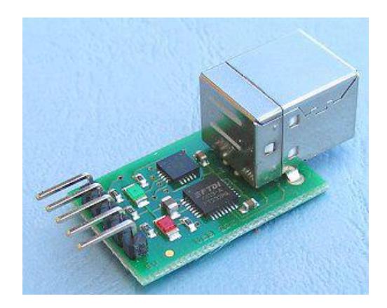
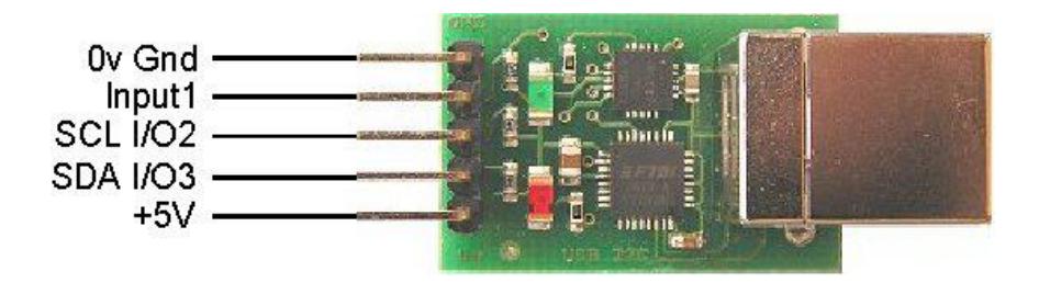
The TPA81 is a thermopile array detecting infra-red in the 2um-22um range. This is the wavelength of radiant heat. The TPA81 can measure the temperature of 8 adjacent points simultaneously. The typical field of view of the TPA81 is 41° by 6° making each of the eight pixels 5.12° by 6°. The array of eight pixels is orientated along the length of the PCB. All communication with the TPA81 is via the I2C bus. Since there is no I2C port on the PC, the TPA81 is interfaced using a I2C-USB interface module. The 5V Vcc is supplied through the USB interface device.
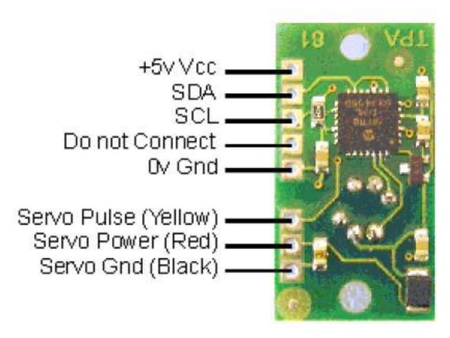
Registers.
| Register | Read | Write |
|---|---|---|
| 0 | Software Revision | Command Register |
| 1 | Ambient Temperature °C | Servo Range (V6 or higher only) |
| 2 | Pixel 1 Temperature °C | N/A |
| 3 | Pixel 2 | N/A |
| 4 | Pixel 3 | N/A |
| 5 | Pixel 4 | N/A |
| 6 | Pixel 5 | N/A |
| 7 | Pixel 6 | N/A |
| 8 | Pixel 7 | N/A |
| 9 | Pixel 8 | N/A |
The USB-I2C module provides a complete interface between your PC and the I2C bus. The module is self powered from the USB cable and can supply up to 70mA at 5v for external circuitry from a standard 100mA USB port.
7.2 Infrared gas sensor (carbon dioxide sensor)
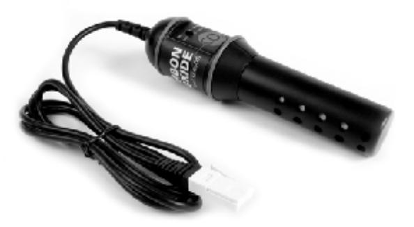
The Vernier CO2 Gas Sensor measures gaseous carbon dioxide levels by monitoring the amount of infrared radiation absorbed by carbon dioxide molecules. It has two settings: low range (0–10,000 ppm) and high range (0–100,000 ppm). Exhaled human breath has a carbon dioxide concentration of about 50,000 ppm. So the high-range setting, 0–100,000 ppm, can be used for measuring human respiration for victim identification. The sensor can make measurements from a distance of about 5 cm (2 inches) from the subject to be tested.
The sensor uses an LED as the source to generate infrared radiation (IR). The IR source is located at one end of the sensor's shaft. At the other end of the shaft is an infrared sensor that measures how much radiation gets through the sample without being absorbed by the carbon dioxide molecules. The detector measures infrared radiation in the narrow band centered at 4260 nm. The greater the concentration of the absorbing gas in the sampling tube, the less radiation will make it from the source through the sensor tube to the IR detector. The temperature increase in the infrared sensor produces a voltage that is amplified and read by a Vernier interface. Carbon dioxide gas moves in and out of the sensor tube by diffusion through the twenty vent holes in the sensor tube.
7.3 Logitech PC Camera C905
A USB camera which is capable of human limbs detection is embedded on the robot to locate the victim. It can also be used to capture images of the victim's situation and report to the operator.
The rescuing-robot with embedded camera will explore the field and look for possible signs of life in the vicinity. The embedded camera is capable of capturing and identifying human limbs. Once there is a victim in the vicinity and it is captured by the robot's camera, say a palm figure, the camera is able to identify it and send the data to the robot. The mechanism is very similar to face-detection or face-recognition function in a commercial digital camera in the marketplace.
The technical specifications of the camera are: Carl Zeiss® optics with autofocus, Native 2MP HD sensor, HD video capture (up to 1600 X 1200*), Up to 8-megapixel photos (enhanced from native 2MP sensor), Microphone with Logitech® Right-Sound™ technology, Up to 30 frames per second video and Hi-Speed USB 2.0 certified.
8. Robot Locomotion
A 4-wheel differential driving solution is implemented on this design. Each wheel is driven with its own DC motor with gear case. The speed is roughly controlled by PWM with solid state relays (SSR) on each wheel motor. However, as the fraction of ground may not be same, the 4 wheel driving method might be a bit inaccurate. Such could be compensated by odometry sensing and SLAM modules.
9. Other Mechanisms
An arm is mounted on the body of the robot. The robot arm basically acts as a human arm with hand. The joints of the arm are controlled via Dynamixel servos, one RX28 and one RX64. Communication to the servo is via the USB-RS485 Port. The sensor and camera are going to be mounted at the end of the arm. Instruction packets are sent to make the necessary movement of the arm.
10. Team Training for Operation (Human Factors)
N/A
11. Possibility for Practical Application to Real Disaster Site
There may be many factors in a real disaster situation which we might not have taken into consideration. Yet, our attempt is to design and implement a reliable rescue robot which can be used in a real disaster situation like in the event of natural calamities such as earthquakes. However in situations such as fire, the human detection module might be unable to work properly due to CO2 and heat emission of fire itself other than human body. In such case, a more expensive thermal camera should be used instead the thermal scanner we are implementing now.
12. System Cost
The overall expense of our system is Singapore $5000. The costs of the key system components are given in the table below. Some other mechanical parts have also been used apart from the mentioned components.
Price list of parts used
| Product | No. | Price per piece | Distributer |
|---|---|---|---|
| Robot | 1 | S$500 | |
| Vernier CO2 gas sensor | 1 | S$300 | www.vernier.com |
| Temperature Sensor | 1 | S$200 | |
| Hokuyo Laser Scanner | 1 | S$1200 | www.hokuyo-aut.jp |
| DC Motors | 4 | S$300 | |
| Computers | 2 | S$500 |
13. Lessons Learned
The robot was designed from scratch and a few attempts have failed due to the fact that step motors cannot carry heavy loads. On top of that, the vehicle's centre of gravity should be kept low in order for it to move on slopes.
For the software part, we have tried a few strategies on SLAM and initial results are promising. The robot is made without odometry sensors; hence the SLAM algorithm must cater for it.
References
[1] A. Ashbrook and N.A.Thacker. (1998, 2009 Oct 10). Tutorial: Algorithms For 2-Dimensional Object Recognition. Available: http://www.tina-vision.net/docs/memos/1996-003.pdf [2] Y. Xia, "Skeletonization Via the Realization of the Fire Fronts Propagation and Extinction in Digital Binary Shapes," IEEE Transactions on Pattern Analysis and Machine Intelligence, vol. 11, pp. 1076-1086, Oct 1989. [3] C. A. Rothwell*, et al., "Canonical Frames for Planar Object Recognition," Lecture Notes in Computer Science, vol. 588, pp. 757-772, 1992. [4] T. F. Cootes, et al., "Active Shape Models Their Training and Application," Computer Vision and Image Understanding, vol. 61, pp. 38-59, Jan 1995. [5] Dec. 25). OpenCV Object Detection Howto:. Available: http://opencv.willowgarage.com/wiki/ObjectDetection [6] D. G. Lowe, "Object recognition from local scale-invariant features.," in International Conference on Computer Vision, 1999, pp. 1150-1157. [7] D. G. Lowe, "Distinctive image features from scale-invariant keypoints," International Journal of Computer Vision, vol. 60, pp. 91-110, Nov 2004. [8] V. Lepetit and P. Fua, "Keypoint recognition using randomized trees," Ieee Transactions on Pattern Analysis and Machine Intelligence, vol. 28, pp. 1465-1479, Sep 2006. [9] V. Lepetit and P. Fua. (2004, Nov 2008). Towards Recognizing Feature Points using Classification Trees. [Technical Report]. Available: Recognizing Feature Points using Classification Trees [10] T. F. Cootes, et al., "A unified framework for atlas matching using Active Appearance Models," Information Processing in Medical Imaging, Proceedings, vol. 1613, pp. 322-333, 1999. [11] T. F. Cootes, et al., "Active appearance models," Ieee Transactions on Pattern Analysis and Machine Intelligence, vol. 23, pp. 681-685, Jun 2001. [12] T. F. Cootes, et al., "View-based active appearance models," Image and Vision Computing, vol. 20, pp. 657-664, Aug 1 2002. [13] P. Viola and M. J. Jones, "Robust real-time face detection," International Journal of Computer Vision, vol. 57, pp. 137-154, May 2004. [14] M. Hu, "Visual-Pattern Recognition by Moment Invariants," Ire Transactions on Information Theory, vol. 8, pp. 179-&, 1962. [15] J. Canny, "A Computational Approach to Edge-Detection," Ieee Transactions on Pattern Analysis and Machine Intelligence, vol. 8, pp. 679-698, Nov 1986. [16] A. Kumar and Y. P. Gupta, "Genetic Algorithms Introduction," Computers & Operations Research, vol. 22, pp. 3-3, Jan 1995. [17] J. Pilet, et al., "Bazar," 1.3.1 ed: CVLab. [18] P. Lester. (2005, A* Pathfinding for Beginners. Available: http://www.policyalmanac.org/games/aStarTutorial.htm [19] S. Koenig and M. Likhachev, "D* Lite," in 18th National Conference on Artificial Intelligence (AAAI-02), 14th Innovative Applications of Artificial Intelligence Conference (IAAI-02), July 28, 2002 - August 1, 2002, Edmonton, Alta., Canada, 2002, pp. 476-483. [20] S. Koenig, et al., "Lifelong Planning A*," Artificial Intelligence, vol. 155, pp. 93-146, 2004. [21] P. Biber and I. Ieee, The normal distributions transform: A new approach to laser scan matching. New York: Ieee, 2003. [22] P. J. Besl and H. D. McKay, "A method for registration of 3-D shapes," Pattern Analysis and Machine Intelligence, IEEE Transactions on, vol. 14, pp. 239-256, 1992. [23] I. J. Cox, "BLANCHE AN EXPERIMENT IN GUIDANCE AND NAVIGATION OF AN AUTONOMOUS ROBOT VEHICLE," Ieee Transactions on Robotics and Automation, vol. 7, pp. 193-204, Apr 1991. [24] J. S. Gutmann, et al., "Fast, accurate, and robust self-localization in the RoboCup environment," in Robocup-99: Robot Soccer World Cup Iii. vol. 1856, M. Veloso, et al., Eds., ed Berlin: Springer-Verlag Berlin, 2000, pp. 304-317. [25] T. Kaminade, et al., "The generation of environmental map based on a NDT grid mapping -Proposal of convergence calculation corresponding to high resolution grid," in Robotics and Automation, 2008. ICRA 2008. IEEE International Conference on, 2008, pp. 1874-1879. [26] F. Lu and E. Milios, "Robot pose estimation in unknown environments by matching 2D range scans," Journal of Intelligent & Robotic Systems, vol. 18, pp. 249-275, Mar 1997. [27] R. Mazl, et al.*, Range scan-based localization methods for mobile robots in complex environments. New York: Ieee, 2001. [28] E. Takeuchi and T. Tsubouchi, "A 3-D scan matching using improved 3-D normal distributions transform for mobile robotic mapping," in 2006 IEEE/RSJ International Conference on Intelligent Robots and Systems, IROS 2006, October 9, 2006 - October 15, 2006, Beijing, China, 2006, pp. 3068- 3073. [29] G. Weiss and E. Vonputtkamer, Map based on laserscans without geometric interpretation. Amsterdam: I O S Press, 1995.