RoboCup Rescue 2010 - Robot League Team iRAP_PRO (Thailand)
Kathawut Uschin, Surachet Inteam, Teerawat Benjawilaikul, Nuttakorn Sae-eaw, Artid Trakultongchai, Praphan Klairith, Wisanu Jitviriya, Pramuk Jenkittiyon
Department of Production Engineering Faculty of Engineering King Mongkut's University of Technology North Bangkok (KMUTNB), 1518 Piboonsongkram Rd. Bangsue, Bangkok Thailand 10800
www.xsense.com · www.hokuyo-aut.jp · http://www.raytek.com
Abstract This paper describes construction and operation of iRAP_PRO the rescue robot team. The iRAP_PRO team participated the last rescue robot competition in World Robocup 2009, Graz, Austria and won the 1st prize of Mix Initiative Championship Award. Our team has two high mobility teleoperative robots and one autonomous robot. Teleoperative robots have front arms which driven by caterpillar with synthetic rubber. As a design, they excel in rough terrain. Besides this, they can identify victims very well with commodity sensors and can move autonomous in radio dropout zone. The autonomous robot has good mobility to move up the incline surface and identify victims by using vision system with image processing and thermal sensor. The three robots are able to create map automatically. The team is prepared for difference scenarios presented in the World Robocup Rescue 2010 in Singapore.
Introduction
"iRAP" is stand for the "Invigorating Robot Activity Project" which is the famous robot club in Thailand. iRAP participated the last rescue robot competition in World Robocup 2009, Graz, Austria and won the 1st prize of Mix Initiative Championship Award. The design of robots competing in the last contest shows very high level of diversity. Our members are including undergraduate students and graduated students from King Mongkut's University of Technology North Bangkok. We have strong practical background for designing, metal works, electrical works, and programming. After working on several prototypes, we finalized on two similar teleoperative robots and one autonomous robot. Our robots have high proficiency in roaming around rough terrain by using caterpillar wheel. We designed stable cameras mounted arm on our robots and on body of robot to help identifying possible victim(s). Full sets of affordable sensors are put on to the system to measure temperature, co2, distance, and to create map. After the national competition, the practice arena was made available for our team to practice. The robot operator is well experienced in navigating the robot(s) under limited scene.
1. Team Members and Their Contributions
The iRAP_PRO has eight members. The names and contribution of each member are listed as follows:
- Kathawut Uschin Electronics design and operator
- Surachet Inteam Teleoperative robot design
- Teerawat Benjawilaikul Autonomous robot design
- Nuttakorn Sae-eaw Controller development
- Artid Trakultongchai Sensors and mapping
- Praphan Klairith Software and controller development
- Wisanu Jitviriya Electronics design
- Asst. Prof .Pramuk Jenkittiyon Team Advisor
2. Operator Station Set-up and Break-Down (10 minutes)
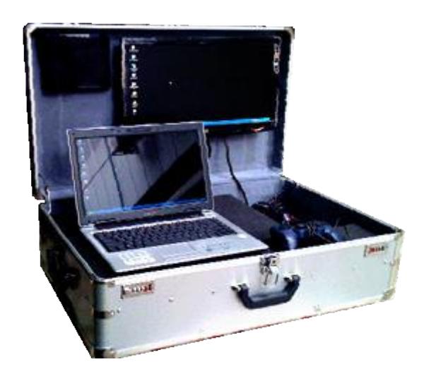
The speed of the set-up and break-down process for each task is very crucial. We realize that the faster we set-up and break-down, the more time we have for other tasks. Our team uses aluminum case as the station. When needed, just open this aluminum case and turn on the switch. The operations can be started within 2 minutes. Inside this aluminum case consists of computer monitor, notebook, access point, printer and UPS. Once all the tasks are completed, the report and the generated map can be quickly printed out.
3. Communications
There are two communication systems used between the iRAP_PRO operator and robots. The first one is wireless LAN based on IEEE 802.11a standard which uses as the main communication system: for controlling robots, receiving video streaming from cameras on robots, and getting sensors feedback for locating the status of robots on computer monitor as well as for the automatic map generation. The second one is the RC controller with radio frequency of 72 MHz as the backup communication system for emergency situation. The range of the working distance is within 400 m for outdoor and 200 m in the building.
Rescue Robot League - iRAP_PRO (THAILAND) Communication Frequencies
| Frequency | Channel/Band | Power (mW) |
|---|---|---|
| 5.0 GHz - 802.11a | Adjustable | 400 |
| 72 MHz | N/A | 1,000 |
4. Control Method and Human-Robot Interface
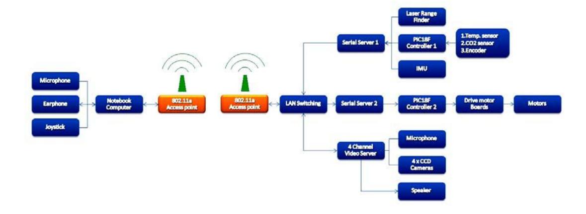
The robots main control is based on one CPU (PIC microcontroller 80 pins). Figure 2 depicts the diagram of the control system which has two main tasks as follows:
4.1
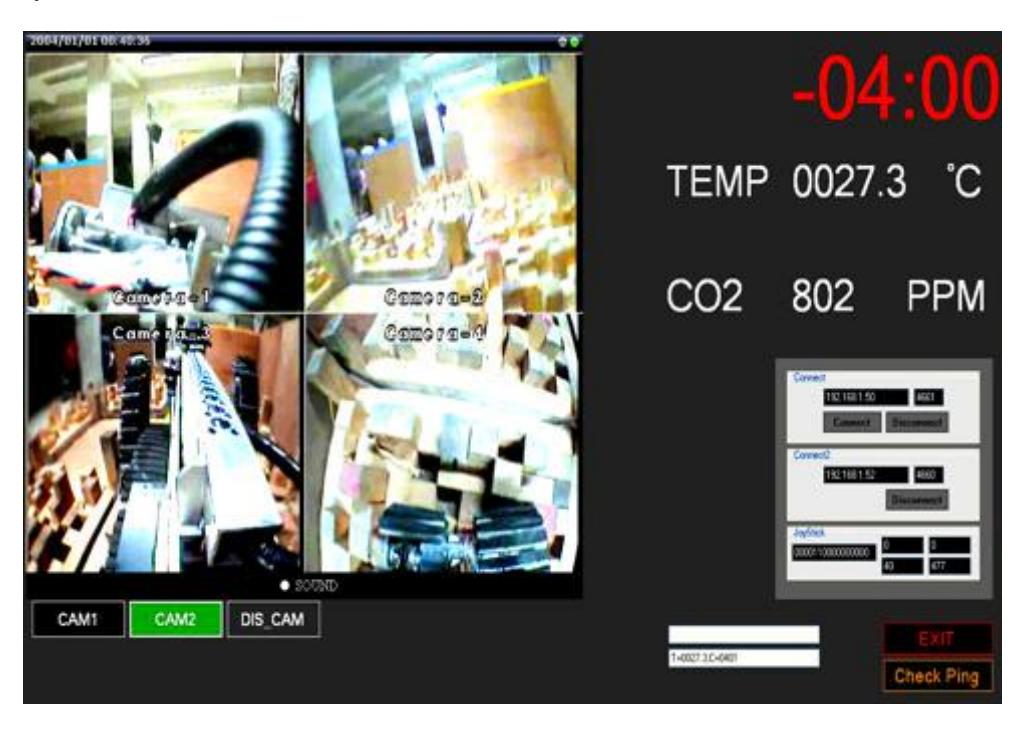
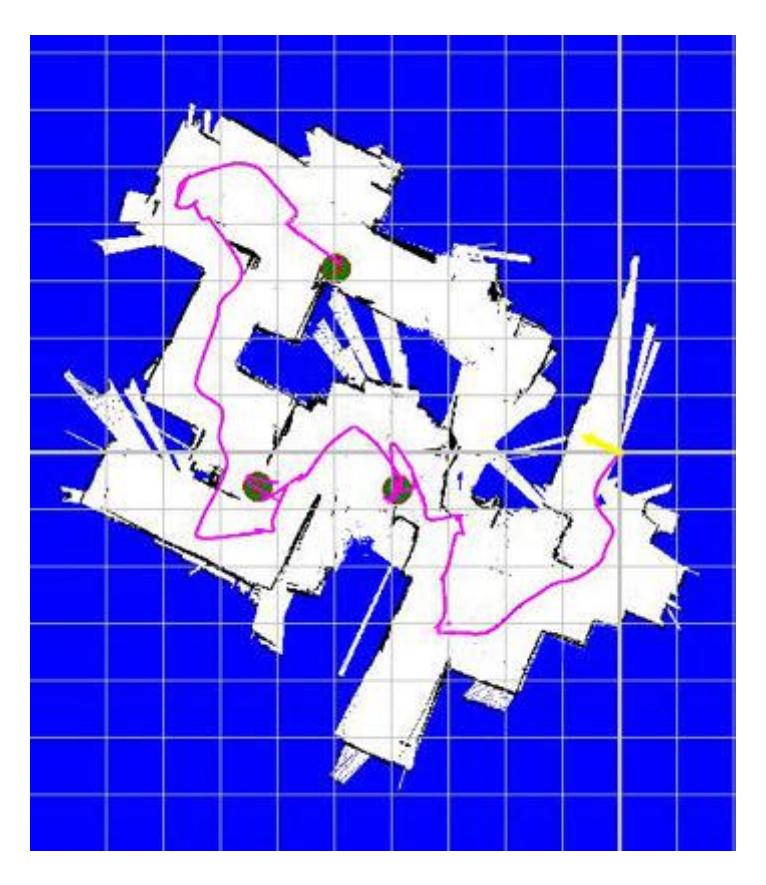
Used for receiving data for identifying status of the robots as shown in Figure 3 and create map automatically as shown in Figure 4. This information will be shown to the robot operator via a computer monitor.
4.2
Used for sending data for controlling the movement by sending the signal to the drive control for controlling DC motor at various locations on the robots
The RS-232 communication system will be used for sending and receiving data of CPU. Therefore, there must be a serial server to convert RS-232 system to Ethernet system.
5. Map generation/printing
Many kinds of sensors are installed on each robot in order to gain the data for processing and creating the 2D map automatically on the operator's computer monitor. The map is generated by using the information from the distance the robot moved from encoders, inclination of the robot and direction of the robot sensed by Inertia Measurement Unit, and distance between the robot and obstacles from laser range finder. However, when the robot move on different kind of surface, the slipping problem can't be avoid. This slipping is major problem for designing and constructing the robot. Therefore, SLAM algorithm [1, 2] used utilized to help generate the map in addition to the information from the encoders.
6. Sensors for Navigation and Localization
Sensors, used for guiding the robot movement and identifying the location of the robots, are described as follows:
6.1 Encoders
Use to measure the distance that the robot moved and use this information to plot on the software along with other kind of sensors.
6.2 Inertia Measurement Unit
Use to measure the inclination and the direction of the robot and use this data to plot along with the distance measured from the encoders.
6.3 Laser range finder
Use to measure the distance of the obstacles in the vicinity of the robot and use this information along with data received by other kinds of sensors to generate the map.
6.4 Quad real time video cameras with wide-angle lens
Quad real time video cameras with wide-angle lens.
7. Sensors for Victim Identification
On each robot, there are four types of sensors for checking and analyzing the victim found by the robot. These sensors are listed as follows:
7.1 IR temperature sensor
Use for checking the temperature of victim found for further analyzing whether the victim still alive or not. The temperature value measured by this kind of sensor will be sent back to computer monitor of the operator.
7.2 CO2 sensor
Use for measure CO2 of victim found for checking breath of the victim.
7.3 High quality microphone and Loud speaker
Use for detecting sound of the victim found and for two-way communication.
7.4 Real time video cameras
Use for investigating of the victim found and send pictures back to the operator for further analyzing the victim.
8. Robot Locomotion
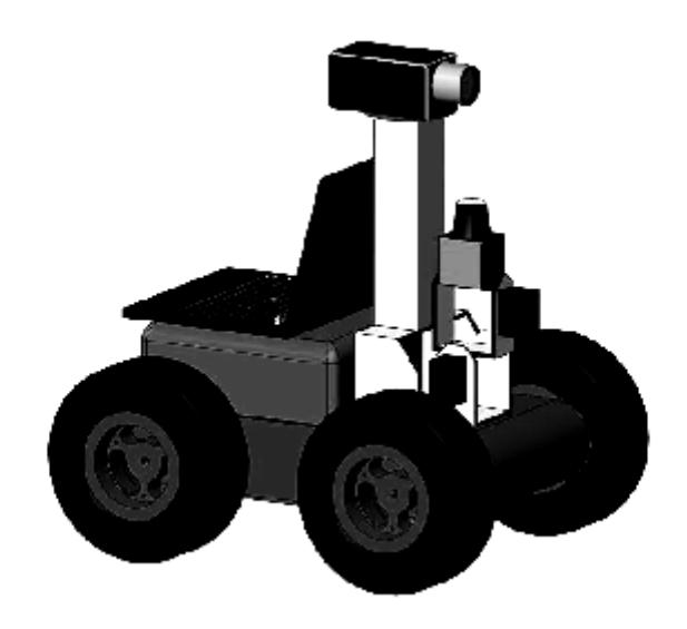
Since the last competition, we have learned many things from our experience and other competitors. In this year, we have built three new design robots consist of one autonomous robot and two teleoperative robots with high performance manipulator. We are looking forward for the best in class award in this competition.
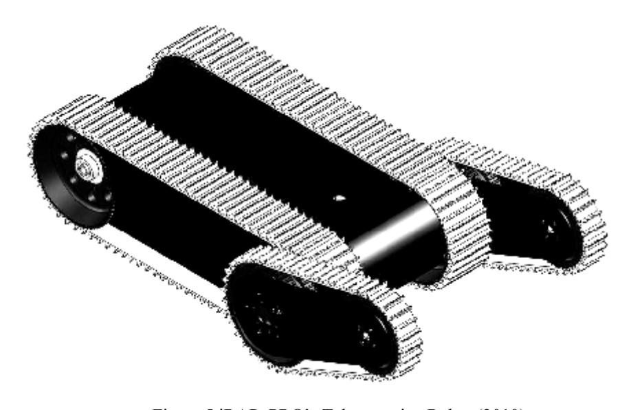
The teleoperative robots are identical robots, as shown in Figure 5 (New model). Our new robot design, used the same platform from our older model, 2009 and improve many parts in order to be toughness, light weight and easy to maintenance as much as possible. The drive system of these new robots is made of the conveyer belt system which can be used on different types of terrain. Each drive system consists of two of 24V, 95 rpm DC motor with gears for the movement on the left and right. The structure of the drive system is made of aluminum. The synthetic rubber is used to make the belt. The robots have a pair of flipper that can be rotated 360 degree. Therefore, the robots have good terrain adaptability for moving through disaster area. The size of each robot is 500 x 650 x 450 mm. and we try to make the weight less than 35 kg.
9. Other Mechanisms
The manipulator of the robot arm which has video camera and sensors installed has high mobility. It can be rotate 360 degree and can be extended closer to the victim, if necessary, to increase visualization. Also there is gripper at the edge of this manipulator which capable of moving objects which weight less than 5 kg and can be stretched up to 1.50 m high from the floor.
10. Team Training for Operation (Human Factors)
The iRAP_PRO has competed in both national and international rescue robot league since 2006. We have learned and continuously developed our skills from 2006. We received the best training through the experiences from real competition round in round out since in each task given in the competition requires not only skills of robot operator but the operator has also to withstand the pressure in the competition environment.
11. Possibility for Practical Application to Real Disaster Site
From the competition in Graz, we demonstrate our robot performance that can be used very well. So, in this year we improve and change a lot of robot parts in the robots in order to make it can be used in the real situation. For example, we increase the toughness of some robot parts, weightless robot as much as possible, extending the effective range of WLAN's signal further and improve quality of video cameras. We plan to use it in the real application soon.
12. System Cost
iRAP_PRO team has three robots. Two of which are teleoperative robots and the other one is autonomous robot. The cost of parts on each robot is listed as follows:
Robot System Cost Breakdown
| Component | Cost |
|---|---|
| Structure of robot and drive train | $1,500 |
| Encoders x 2 | $120 |
| Xsense Inertia Measurement Unit | $2,800 |
| Hokuyo laser range finder | $2,100 |
| Temperature sensor | $350 |
| High quality microphone | $45 |
| Video cameras x 4 | $320 |
| CO2 sensor | $100 |
| Controller and electronics | $350 |
| Access point IEEE 802.11a | $180 |
| Quad channel video server | $750 |
| Serial server | $200 |
| Total Cost | $8,815 |
13. Lessons Learned
We have participated in Rescue Robot since 2006. We have learned a lot from the experiences in competing each year. We have seen what other did and we have learned how improve our robot every year. More importantly, we have learned that we cannot be successful without the cooperation of every team member.
Acknowledgement
The iRAP_PRO team was supported in parted by grants from the Siam Cement Group, Thai Robotic Society, Department of Production Engineering, Faculty of Engineering and King Mongkut's University of Technology North Bangkok. Most of the works were machined at the technology service center, King Mongkut's University of Technology North Bangkok, Thailand.
The final manuscript of this paper was prepared by Chatchai Sermpongpan and Artid Trakultongchai
References
- R. Siegwart, I, Nourbakhsh: Introduction to Autonomous Mobile Robots (2004)
- Sebastian Thrun, Dieter Fox, Wolfram Burgard: Probabilistic Robotics (1999-2000)
- www.xsense.com
- www.hokuyo-aut.jp
- Thermalert manual Raytek Corp., Available: http://www.raytek.com