RoboCupRescue 2011 - Robot League Team Barbaros (Turkey)
Sırma Yavuz, M. Fatih Amasyalı, Erkan Uslu, Zeyneb Kurt, Ozan Özışık, Uğur Ergül, M.Said Aydemir, Sümeyra Balcı
Yıldız Teknik Üniversitesi Computer Engineering Department Beşiktaş, İstanbul TR34349 Turkey
Abstract This paper describes the robots constructed by the team Barbaros, as well as the operation and strategies of the team. Two robots are being constructed by the team, for the competition. The wheeled model PARS is fully autonomous and will be used in yellow arena. For the rest of the competition a tracked model SIRIUS will be used. Both of the robots run SLAM and victim detection algorithms on board and are able to continue navigating without teleoperarion. The team aims to contribute towards the achievement of full autonomy by improving the SLAM and victim detection process.
Introduction
Team Barbaros is a part of the robotics research group founded within the Computer Engineering Department of Yıldız Technical University. Our group is mainly working on SLAM (Simultaneous Localization and Mapping) algorithms and developing its own autonomous mobile robots since 2007 [1, 2]. The team includes one undergraduate and two graduate students who are recently joined to the research group. Other members of the team have a strong background on programming, electronic and mechanical design. Contributing towards the production of robust and more intelligent search and rescue robots is the most important goal of the group.
We are planning to use two different robots during the competition. Our first robot, called PARS, is a wheeled model and suitable for yellow arena only. PARS is an improved version of our pervious robots, it is preferred due to its simple mechanical design and effective sensor combination. We have used this model on different localization and mapping projects as well as obstacle avoidance or path planning projects [3, 4]. With relatively cheaper sensors and simple design we have obtained good results. For the competition, our original model gone under some modifications; such as resizing and adding sensors. Our second robot, called SIRIUS, is a tracked model having two flippers in front and a manipulator on top; it is designed to cope with rough terrain.
1. Team Members and Their Contributions
The list of the team members and their main responsibilities are as follows:
- Sırma Yavuz Advisor, also responsible of mechanical design, electronics and SLAM software development
- M. Fatih Amasyalı Advisor, also responsible of victim detection and image processing software development
- Erkan Uslu Operator, electronics, controller programming
- Zeyneb Kurt SLAM software development • Ozan Özışık SLAM software development • Uğur Ergül Communication infrastructure
- M. Said Aydemir Control interface design, victim detection • Sümeyra Balcı Image processing software, victim detection
We also would like to thank:
- S. Metin Yavuz for his support on mechanical and electronic design and implementations
- Yıldız Technical University Scientific Research Projects Coordination Department for their support on our projects
2. Operator Station Set-up and Break-Down (10 minutes)
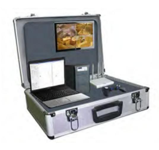
An aluminum wheeled case as shown in Fig.1. will be used to carry all necessary items for the operator station. The station will be powered up and powered down with one button. The operation case contains one laptop, one lcd monitor one portable printer, one gamepad, one access point and a power unit. To carry the robots we plan to use another trolley, it will be constructed according to size of our robots. Although other team members will assist the operator to carry the operation case we aim to have only one operator to set up and break-down the operator station within 10 minutes. Two people will be responsible of carrying the robots inside and outside the competition arena.
3. Communications
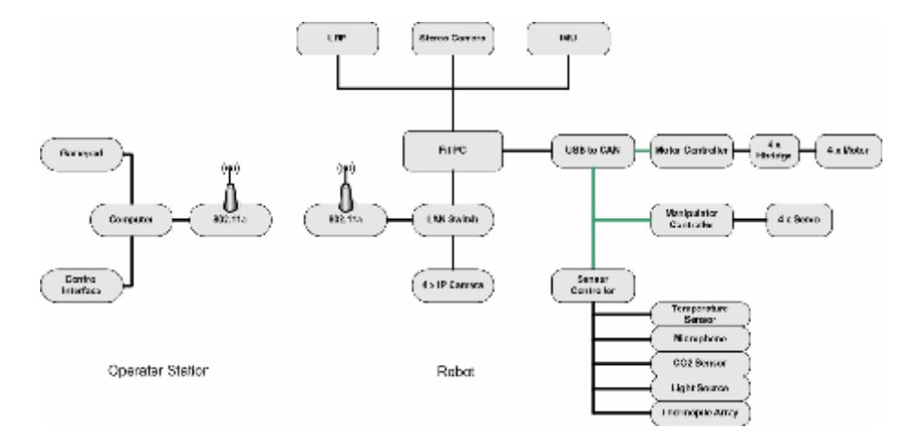
There are two access points in our system, one on the robot side and the other on the operator station. These access points support both 802.11a and 802.11g; however we plan to use 802.11a to communicate between robots and the operator station. The FitPC used on our robots supports 802.11g and it will be connected to the access point via Ethernet cable, the IP cameras used on SIRIUS are also connected to the access point with Ethernet cables. General setup of our system is shown in Fig. 2.
The wireless communication is between the access points require a selectable 802.11a compatible band.
There is a headset to be used by the operator requiring Bluetooth communication. As a backup communication between the robots and the operator station we plan to use Bluetooth adapters.
Communication requirements of the team
| Rescue Robot League | |||
|---|---|---|---|
| BARBAROS (TURKEY) | |||
| Frequency | Channel/Band | Power (mW) | |
| 5.0 GHz - 802.11a | selectable | ||
| 2.4 GHz - Bluetooth | spread-spectrum | ||
| 2.4 GHz - Bluetooth | spread-spectrum |
4. Control Method and Human-Robot Interface
The team will join the competition with two robots; the first one, PARS, is planned to be used in yellow arena only and it is fully autonomous. It will try to cover the whole area using SLAM algorithms relying on sensor data and will generate the map of the area automatically. Victim detection is planned to be fully autonomous as well. The robot will only send the necessary information to the operator's computer for him to annotate and print the victim information and the map.
For the rest of the competition our second robot SIRIUS will be used and it has partial autonomy; the operator will interfere only when necessary. The operator may send commands to direct the robot and the manipulator carrying the camera towards victims to help victim detection. Operator will use a wireless gamepad and a Bluetooth headset.
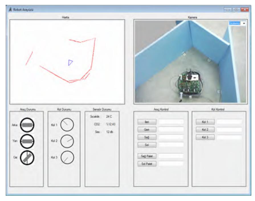
For both of the robots algorithms will run on the robots and only the automatically generated maps and video streams will be sent to the operator's computer. Fig.3. shows the interface currently used by the operator. The interface will be improved and finalized by the time of competition. Currently the screen is divided into four parts.
On the upper left part of the screen, operator will be able to fallow the sensor based map generated by the SLAM algorithm and may eliminate points he considered to be faulty, he will also see the position of the robot as calculated by the SLAM algorithm.
The upper right part of the screen will show the video streams from IP cameras, allowing operator to compare the robot position information generated by the algorithm with the real one. Also operator will be able to notice the victims on this part of the screen and direct the robot and manipulator towards the victim to help victim detection software to recognize the victims.
The lower left part of the screen currently shows the position of the robot according the IMU data and the position of the manipulator. Finally the right part of the screen currently allows operator to direct the body and the manipulator of the robot by entering velocity and servo angle commands, this is for testing purposes and will probably be removed or redesigned by the competition. Normally operator will be using a gamepad to direct the robot and the manipulator.
The explanations given above, are mostly valid for our second robot SIRIUS, since our first robot PARS will be fully autonomous and operator will be only watching the screen during operation and printing the map at the end.
5. Map generation/printing
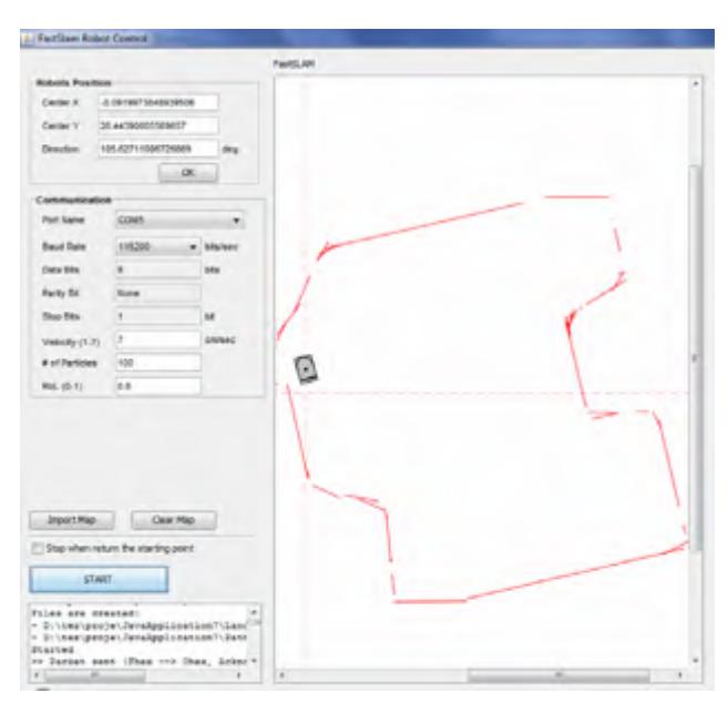
To generate a 2-D map of the environment and to determine the positions of the robots or victims we use SLAM algorithms. Operator can follow the landmarks and victims found by the algorithm on the screen as shown in Fig. 4. We plan to extend the software, to provide an information sheet for each victim found, to allow operator to edit the victim information. Operator will be able to print the victim information and the final map using the print button on the software.
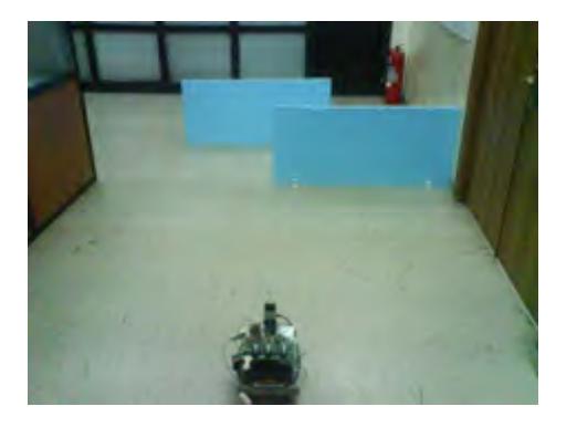
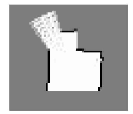
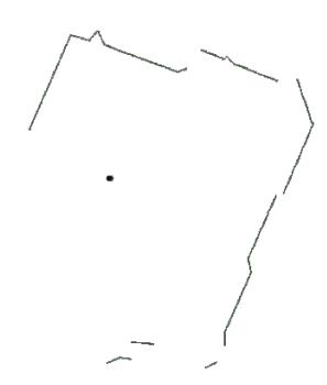
We are able to produce reliable sensor-based maps using FastSlam and EKF Slam algorithms [5, 6]. A sample sensor-based map generated is given in Fig. 5. We have also some experience on applying line extraction methods to the sensor-based maps but for complex environments, applying such methods may result in unclear maps. An example of a map after application of line extraction methods is given in Fig. 6. Our previous work on SLAM algorithms primarily rely on LRF and encoder data for mapping and localization. Since the competition site is more complicated, including ramps, stairs or holes on the walls we are currently incorporating IMU and camera data into our software. In our application we aim the operator to add few annotations to the information sheet provided by the software and not to interfere with automatic map generation at all.
6. Sensors for Navigation and Localization
As stated before we have two different robots; PARS is a fully autonomous robot and uses relatively cheaper sensors for navigation and localization. SIRIUS is a tracked model and equipped with more advanced sensors. In this section, the list and basic properties of the sensors are given for each robot.
6.1 Navigation and Localization Sensors on PARS
- Shaft Encoder: It is placed on the front wheel, since it is mounted on the same shaft with the motor the distance taken is measured accurately.
- Rotary Position Sensor: It is a 106° position sensor spring returned clockwise, placed on steering mechanism. Although the steering angle is generated by the algorithm, this sensor allows the algorithm to detect any obstacles preventing the movement of the wheel and to correct the position information accordingly.
- Laser Range Finder (LRF): The field-of-view for this sensor is 240 degrees and the angular resolution is ~0.36 degrees. It can measure distances from 20mm to 4 meters.
- IR and Ultrasonic Range Finders: Although these sensors are not crucial for mapping or localization, they are used to sense any obstacles close to the ground and are not detectable by LRF.
- Stereo Vision System: The system has two cameras separated by ~11 cm, it supports WiFi communication via 802.11g. Stereo vision data is not originally used as a part of the navigation and localization software. We intent to use it to correct the localization data, and the generated map accordingly.
The pictures of the sensors used on PARS are given in Fig. 7.

6.2 Navigation and Localization Sensors on SIRIUS
- Inertia Measurement Unit (IMU): It provides 3D orientation, acceleration, 3D rate of turn and 3D earth-magnetic field data.
- Laser Range Finder (LRF): The field-of-view for this sensor is 240 degrees and the angular resolution is ~0,.36 degrees. It can measure distances from 20mm to 4 meters.
- IR and Ultrasonic Range Finders: Although these sensors are not crucial for mapping or localization, they are used to sense any obstacles close to the ground and are not detectable by LRF.
- Stereo Vision Camera: It has a resolution of 640x480 pixels at 48FPS. It is connected to FitPC placed on the robot using IEEE-1394 (FireWire). Stereo vision data is not originally used as a part of the navigation and localization software. We intent to use it to correct the localization data, accordingly the generated map.
The pictures of the sensors used on PARS are given in Fig. 8.

7. Sensors for Victim Identification
Same type of sensors is used on both of our robots, to locate and determine the state and situation of the victims. We aim to automate the victim detection process as much as possible. Various image processing algorithms, including skin tone detection and feature matching algorithms, are used. We have developed software based on SURF (Speeded up Robust Features) algorithm to recognize the different parts of the victims [7].
The sensors used for victim identification are listed as follows:
- Stereo Vision Camera: It has a resolution of 640x480 pixels at 48FPS. It is connected to FitPC placed on the robot using IEEE-1394 (FireWire). Stereo vision data is not originally used as a part of the navigation and localization software.
- Thermal Array Sensor: Measures the absolute temperature of 8 adjacent points in its field-of-view simultaneously.
- CO2 Sensor: It is used to check the breathing for the victim found.
- Microphone and speaker: These are used to detect the sound of the victim.
8. Robot Locomotion
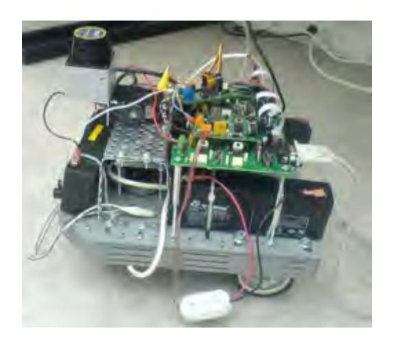
Our team uses two robots. Our first robot, PARS, is a wheeled model. A picture of the initial version of PARS is given in Fig. 9. , currently it is used to develop SLAM algorithms. It is aimed to be completely autonomous and to be used in yellow arena only.
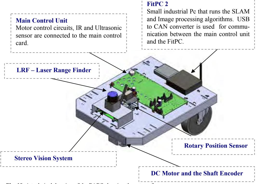
The general setup of the PARS is shown in Fig. 10. For the competition, our original model gone under some modifications; such as resizing and adding sensors.
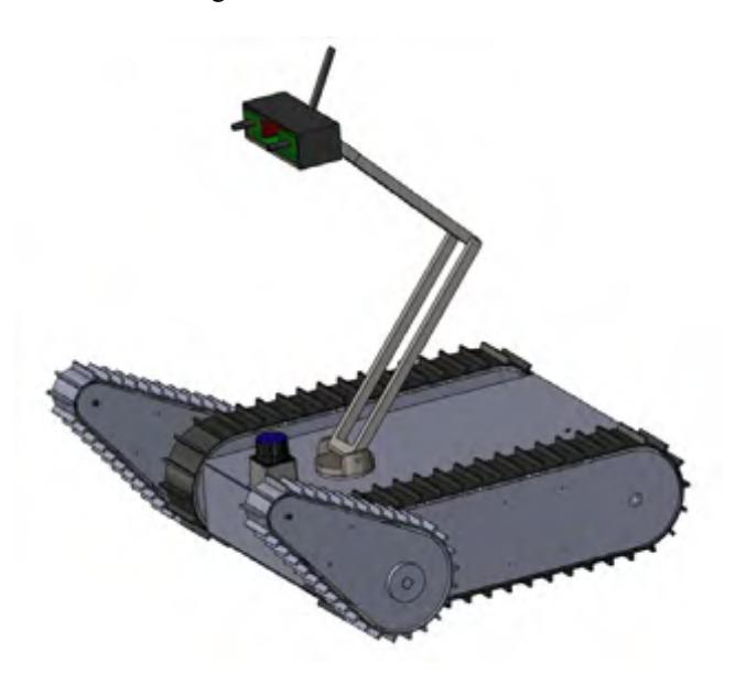
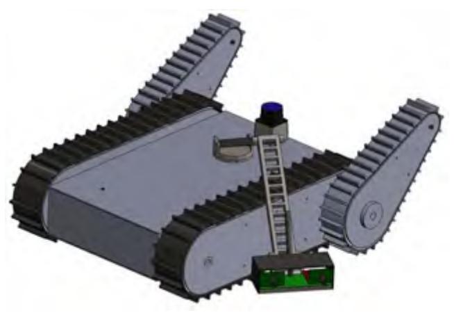
Our second robot, SIRIUS, is a tracked model having two flippers and a manipulator on top; it is designed to cope with rough terrain. The manipulator is a 4-dof model carrying the stereo camera and directed by the operator. This model is semiautonomous; it can navigate, generate the map and identify the victims in sight without teleoperation. Teleoperation is used to direct the robot towards victims to help victim detection and to release the robot in case it gets stuck. Fig. 10. and Fig. 11. shows the technical design of the robot SIRIUS. The flippers of the robot and the manipulator can rotate 360 degrees.
9. Other Mechanisms
The electronic circuits of the both robots are designed by the team. Most important components are explained in this section. Also the communication system between the robots and the operator's pc is detailed.
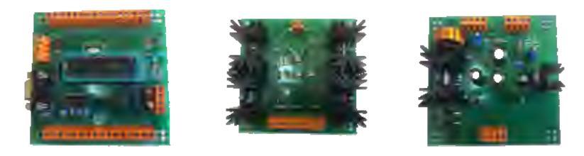
The main control unit, h-bridge motor driver and the power unit are shown in Fig. 12. , respectively. Main control unit is used to collect sensor data and transmit them to the FitPC via can bus. The commands generated by the algorithm are also transmitted to the motors or servos through main control unit. USB to CAN converter is used for communication between the FitPC and the main control unit.
For the motor driver circuit H-bridge arrangement is used to be able to reverse the polarity of the motor or to brake. It is also connected to the main control unit via can bus.
Finally the power unit supplies the 5 volt to the main control unit and to the sensors.
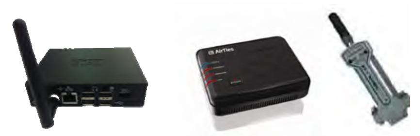
As stated before, the main wireless communication system of the team complies with IEEE 802.11a. Since FitPC is only compatible with 802.11g, it is connected to a access point which complies with both 802.11a and 802.11g. Also as a backup communication system bluetooth adapters are available on our robots. The bluetooth adapters are connected to the FitPC and to the operator's pc via usb ports. The main components of the communication system are shown in Fig. 13.
10. Team Training for Operation (Human Factors)
We use a gamepad as our control interface device. It is configured to generate simple commands. Separate set of buttons are used to control the body, flippers and the manipulator of the robot. We are working on selecting the most effective set of commands to allow the operator to input as few commands as possible to control the robots.
We will also set up an environment similar to the competition for our operator to exercise. This is also necessary to test our robots effectively.
11. Possibility for Practical Application to Real Disaster Site
On a real disaster site, the main advantage of our system is being able to move autonomously. Communication would arise as an important problem in most disaster sites. If the robot is not able to get back where it has started, the information it gathered inside the ruins becomes completely useless. Although we still have a long way to go, the strongest feature of our system is its autonomy. In terms of mechanical design, our second robot SIRIUS will be able to cope with rough terrain better, but will probably need much more work to be successful on a real and completely unknown disaster site.
12. System Cost
The components, providers and the cost of our robots are given in Table 2 and Table 3 respectively. Total prices do not include the mechanical and electronic parts of the system which are very variable.
PARS system cost
| Name | Brand - Model | Web |
|---|---|---|
| Robot Base | ||
| Electronics - Main Control, H bridge, power unit | ||
| Wheels | EB series | http://www.emesteker.com/ |
| Motor | 2KE-2032 Series | http://www.zhengke.cn |
| Encoder | Hengstler | http://uk.rs-online.com |
| Servo | Futaba | http://www.modelmerkezi.com |
| Rotary position sensor | Vishay | http://uk.rs-online.com/ |
| Battery | Yuasa 12v | http://www.yuasabatteries.com/batteries.php |
| Laser Range Finder | URG-04LX | http://www.hokuyo-aut.jp |
| Stereo Camera | Surveyor Stereo Vision System | http://www.surveyor.com/blackfin/index.html |
| FitPC | fit-PC2 Linux | http://www.fit-pc.com/web/ |
| CO2 sensor | TGS4161 | http://www.itektr.com/figaro.php |
| Thermopil | Devantech TPA81 8x1 Thermopile | http://www.acroname.com/robotics/parts/R255-TPA81.html |
| Ultrasonic | Devantech SRF04 | http://www.acroname.com/robotics/parts/R145-SRF08.html |
| IR Sensor | Sharp | http://www.acroname.com/robotics/info/articles/sharp/sharp.html |
| TOTAL PRICE | $ 4500 |
SIRIUS system cost
| Name | Brand - Model | Web |
|---|---|---|
| Robot Base | ||
| Electronics - Main Control, H bridge, power Card | ||
| Motor | 2KE-2032 Series | http://www.zhengke.cn |
| IMU | Xsens 6 dof IMU | http://www.xsens.com |
| Servo - manipulator | Futaba | http://www.modelmerkezi.com |
| LRF - Laser Range Finder | URG-04LX | http://www.hokuyo-aut.jp |
| Access Point | Airties | http://www.airties.com |
| IP Kamera POE Switch | Jetnet 3810G | http://www.korenix.com |
| Stereo Camera | Bumblebee® 2 System | http://www.ptgrey.com |
| FitPC | fit-PC2 Linux | http://www.fit-pc.com |
| CO2 sensor | TGS4161 | http://www.itektr.com |
| Thermopil | Devantech TPA81 8x1 Thermopile | http://www.acroname.com |
| Ultrasonic | Devantech SRF08 | http://www.acroname.com |
| IR Sensor | Sharp | http://www.acroname.com |
| Battery | Yuasa 12v | http://www.yuasabatteries.com |
| TOTAL PRICE | $ 13000 |
13. Lessons Learned
This section will be completed after the competition..
References
- Thrun, S. , Burgard, W. and Fox D.: Probabilistic Robotics, The MIT Press, Cambridge, Massachusetts (2005)
- Kurt Z., "Development of Intelligent SLAM Algorithms, Master Thesis, Yıldız Teknik Üniv., (2007)
- Özışık O., Yavuz S.: Fuzzy-Neural Robot Controller for Unknown Environment Exploration, 1st International Fuzzy Systems Symposium (FUZZYSS09), Ankara (2009)
- Şahin O., Yavuz S.: Autonomous Parallel Parking Robot, International Symposium on Innovations in Intelligent Systems and Applications (INISTA 2009), Trabzon (2009) 5.. Özışık O.:Simultaneous Localization and Mapping with Robot Team, Master Thesis, Yıldız Teknik Üniv., (2010)
- Özışık O., Yavuz S.: An Occupancy Grid Based SLAM Method", IEEE Computational Intelligence for Measurement Systems and Applications (CIMSA 2008), İstanbul (2008)
- Bay H., Tuytelaars T., Van Gool L.: SURF: Speeded Up Robust Features, ECCV 2006, (2006)