RoboCupRescue 2011 - Robot League Team MRL Rescue Robot (Iran)
A. M. Shahri, J. Chegini, A. Karambakhsh, A. H. Mashat, M. Rahmani, M. J. Namazifar, M. A. Mashat, M. Karimi, B. Mahdikhani, V. Azizi, V. Khorani, S. M. R. Mirfakhar, N. Ajilforoushan, M. kiyaei, M. Shahsavari
Mechatronics Research Laboratory, Azad University of Qazvin, Qazvin, IRAN
Abstract In this paper the Mechatronics Research Laboratory (MRL) rescue robot team from Azad University of Qazvin and its robots are explained. We have designed and built a new autonomous robot, developed our tele-operated robot and a new flying robot for different situations/arenas. Our main goal of this activity is to achieve a practical rescue robot for real situation such as earthquakes. We have also arranged to initiate some research programs on autonomous mobile robot such as; simultaneous localization and mapping, navigation strategies, collision avoidance algorithms, sensor fusions, automatic victim detection and search algorithms.
Introduction
A rescue scenario is usually unstructured and unstable, therefore requiring the use of complex mechanical design and control strategies both in software and hardware levels. On the other hand, saving the victims should be done quickly, so implementing high technologies such as robotics could be helpful for search and rescue operations. There are so many earthquakes every year in many countries such as Japan, USA, Turkey and Iran.
Our team members in the Mechatronics Research Laboratory (MRL) are planning not only to take part in the competition but also to get enough knowledge to achieve a practical robot to help search and rescue operations in a disaster situation.
In this paper the MRL rescue robot team and its robots are explained. Our main goal of this activity is to achieve a practical rescue robot for real situation such as earthquake which is very common in our country.
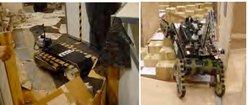
Obviously, based on the environmental situation a special robot with proper abilities is required. In other words, there could be no unique robotics solution for a rescue mission in a disaster situation. As a result we have designed different robots with different maneuverability. For example NAJI-I and NAJI-IV with a high power and flexible mechanism which overcome hard obstacles are also capable of supporting a powerful manipulator for handling objects. Fig.1 illustrates NAJI-I in Japan-2005 and NAJI-IV in China-2008.
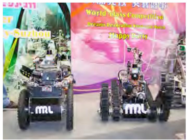
NAJI-III is a new design and modified version of NAJI-I which is more powerful and flexible while it is lighter and smaller. In 2008 we designed a new Autonomous robot NAJI-V for the competitions. Fig 2 illustrated the NAJI-V and NAJI-III in China2008. We achieved 2nd in china 2008 using this two robots.
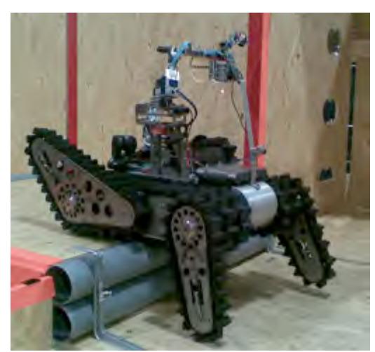
There are so many rough and hard terrains in a disaster situation which the rescue robot should be fast enough and low weigh to pass and explore environment quickly while it is stable. So we developed a new design with 4 arms named NAJI-VI which is equipped to roller cylinders in its bottom.
NAJI-VI with the new stylish is now very stable and more efficient than later. And using new Mechanical stylish in NAJI-VI makes this robot more power full and effective in Step-Filed zones as later. In other word NAJI-VI is a combination of NAJI-I and NAJI-III. This new design give use the power of NAJI-I in Climbing and the Power of NAJI-III in Step-Field, and more ability than our previous robots. Figs 3 illustrate NAJI-VI in US 2007.
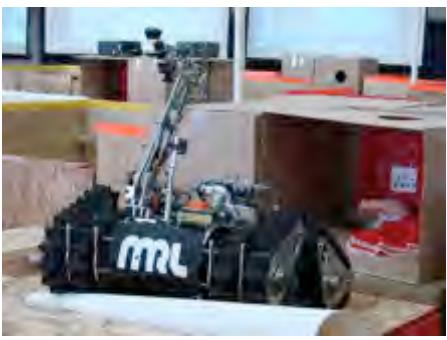
NAJI-I, II and NAJI-III are good examples of such a robot while NAJI-VI with a novel mechanical design is faster, flexible and more stable. NAJI-VI's caterpillar covers whole body and makes it capable cross obstacles such as step fields easily. Fig, 4 illustrates NAJI-VI in Austria 2009 which using this robot we achieved third place.
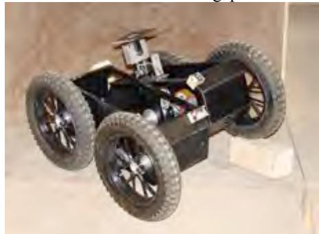
In 2010, we designed and manufactured two new robots. NAJI-VII a tele-operated robot and NAJI-VIII an Autonomous robot designed for 2010 Singapore competitions. NAJI-VIII which is facilitated with most required sensors is an autonomous mobile robot to carry out different research programs which is also suitable for the yellow and radio off zone arena. Due to improvement in autonomous arena the mechanical platform of autonomous robot improved as well. Therefore we designed NAJI-VIII which uses four wheel differential moving system so can cross easily from sloped floor arenas. All our robots are powered by Embedded PC based on Linux (PCT1 Linux) and a software framework (NRRServer2) which are able to process data and control the robot in Real-time. Fig, 5 illustrates our last autonomous robot called NAJI-VIII. our tele-operated robot NAJI-VII in Singapore 2010 is illustrated in Fig 6.
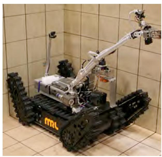
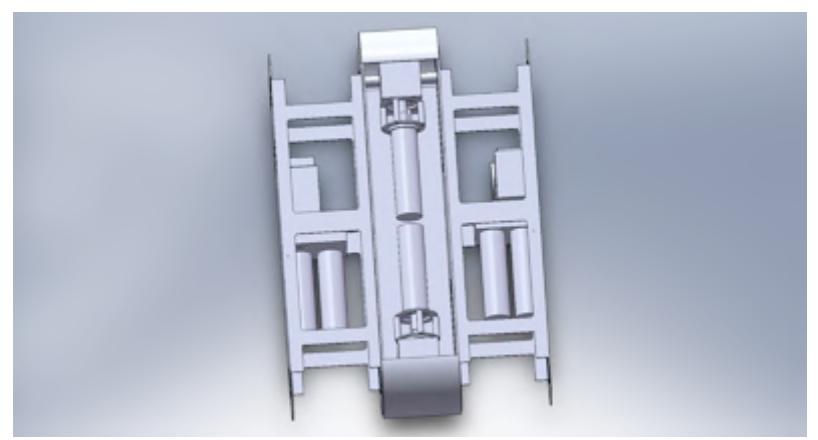
One of the main problems of NAJI-VII was its limitation in speed. We developed our tele-operated robot NAJI-VII to make it faster. We employed two motors in parallel in the main body; therefore, we achieved more speed with the same torque. Fig. 8 illustrates the latest development in NAJI-VII.
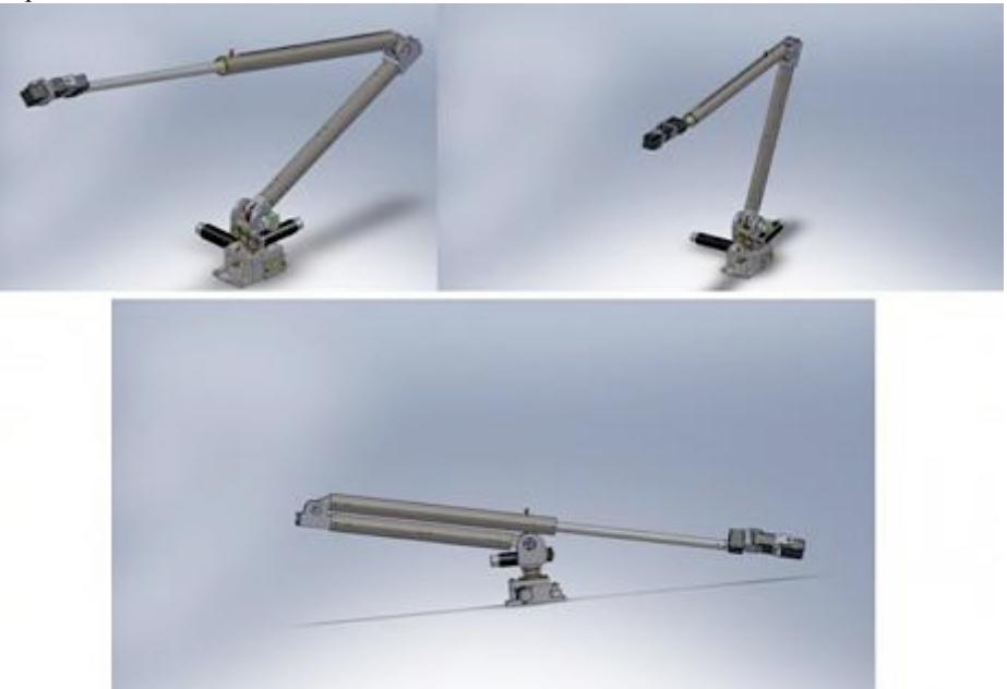
One of the main issues in rescue robot field is manipulators. We designed a new manipulator for 2011 competitions. This 6 degree of freedom manipulator will able us to reach victims in 1.6 meter height. Fig. 9 illustrates pictures of our new designed manipulator.
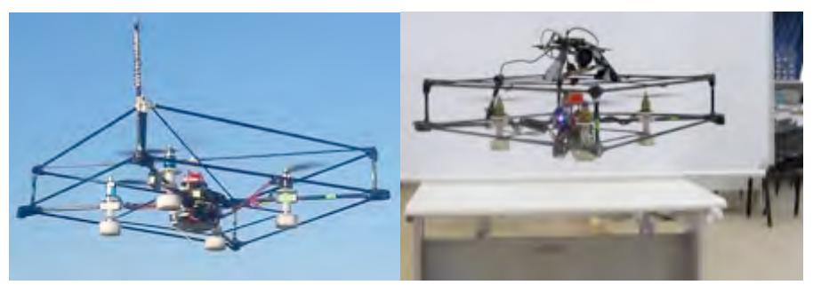
Our aim is to develop and manufacture robots for helping peoples in disasters. Due to this goal, we started our research on flying rescue robots last year. We implemented and prepared a flying robot to be used in rescue mission. It is QUADVIN-Flyer-I that is shown in Fig. 10. This robot is suitable for flying over impassable arenas and gathering information about environment. This robot is equipped via IMU, laser scanner, un-board real-time PC, camera and sonar sensors. This robot can fly autonomously or manually. Collision avoidance, transmitting camera and SLAM information to an earth-working robot in case of autonomous mission or to an operator station in case of manual missions are other abilities of the implemented robot.
Team Members and Their Contributions
| No. | Name | Role |
|---|---|---|
| 1. | A. M. Shahri | Team Leader |
| 2. | J. Chegini | Team Organizer, Electronic |
| 3. | M. J. Namazifar | Software |
| 4. | A. Karambakhsh | Software |
| 5. | V. Azizi | Software |
| 6. | A. H. Mashat | Electronics |
| 7. | M. Karimi | Electronics |
| 8. | B. Mahdikhani | Electronics |
| 9. | M. A. Mashat | Mechanical |
| 10. | M. Rahmani | Mechanical |
| Azad University of Qazvin | Sponsor |
2. Operator Station Set-up and Break-Down (10 minutes)
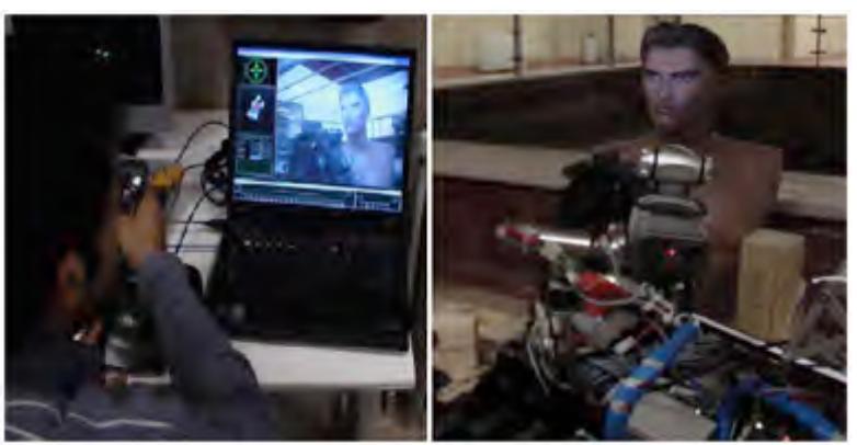
In the rescue operation it is compulsory to set-up and break down as soon as possible in less than 10 minutes. We've designed a Mobile Control Pack (MPC) including; notebook, joystick, access point, antenna, I/O Extension board and case with appropriate connectors so the operator can setup and drive user friendly. Fig.5 illustrates the Control Pack and GUI of the robot.
2. Software Overview
The software controller is developed to be executed on Real-time Linux. Moreover, it is equipped with intermediate software layer to communicate with RT-HAL in lower level and Wireless LAN in higher level. The low level software (NRRServer) sends the generated path, Log file and sensors data to central computer in the operator station in semi-autonomous. In fully autonomous, NRRServer sends the data to a laptop which is located on the robot.
2.1 Real Time Hardware Abstracted Layer (RT-HAL)
It should be noted that for executing a high level control algorithm in a robot and consequently decreasing the system dependency on intermediate devices, employing an abstracts layer is unavoidable. To approach this goal the Real Time Hardware Abstracted Layer (RT-HAL) is designed in modular form on Linux Kernel RT-HAL in order to directly access to the lower layer (hardware) and upper layer (high level controlling process). NRRServer implemented on RT-HAL.
- Collecting the sensors data
- Sensor fusion and data processing and noise filtering
- Low Level controlling
- Localization and Mapping
- Navigation and obstacle avoidance
- A communication interface to high level process
Sensors data will be collected by associated data acquisition module and passed to sensor fusion process to be fused and acquire a better perception of environment. RT-HAL by implementing the driver as a device files, prepares a base for high level application to send their controlling command to actuators. Consequently NRRServer decreases the high level application independency and prepares the standard API to communicate with the hardware which leads to code the application in any programming languages.
3. Hardware Overview
The robots which are based on differential drive system are equipped with sonar sensor, Laser Scanner, CO2 sensor, thermopile array detecting infra-red sensor, IMU, digital compass, optical encoders and digital/analog cameras. The computational system is PCM 6892, PCM 8200, PFM 620s and GENE-8310 by 512 MB Compact Flash Memory, 128 MB RAM. The operating system is PCT-Linux which optimized and equipped with Hardware Abstracted Layer for best performance.
4. Autonomous Robot System Overview
The robot system overview is designed based on three levels High, Abstraction and Low level top to bottom including the following steps orderly:
- Localization: Given sensors and a map, where am I?
- Vision: Is there any victim's signal, what should I do?
- Mapping: Given sensors, how do I create a useful world model?
- Searching Algorithms: Given an unknown world but a known goal and local sensing, how can I get there from here?
- Kinematics: if I move this motor somehow, what happens in other coordinate systems?
- Control (PID): what voltage should I set over time?
Fig 12 illustrates autonomous robot data processing and control system.
5. Semi - Autonomous Robot System Overview
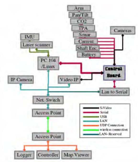
The control scheme of our remote robot is partially autonomous. It means that the cameras images are sent to the computer and process by operator to navigate the robot. All other sensors information's are also sent to the operator to investigate the arena and detect all possible victims.
Although the map generation is autonomous and manual, when a victim is located, operator has to define the victim conditions based on the sensors data. In order to save time, a proper GUI is designed with several push bottom keys to define the victim's condition just by clicking the mouse button.
All the sensors data are collected in a data bank to be used even off-line after the operation. Fig 13 illustrates the high level overview of semi autonomous robots.
6. Flying Robot Overview
Quadrotors are an emerging rotorcraft concept for unmanned aerial vehicle (UAV) platforms. The vehicle consists of four rotors in total, with two pairs of counterrotating, fixed-pitch blades located at the four corners of the aircraft [paper 1]. Having four rotors capables the quadrotor to be controlled without using swash plats to change the pitch angle of the blades unlike the helicopters. This simplifies both the design and maintenance of the quadrotor. Using four rotors capables the quadrotor to be stable in fly and carry more payload than other flying platforms. This makes the quadrotor a suitable platform for being used as an autonomous robot which can carry equipments like laser scanner, camera, on-board real-time PC, and etc.
Dynamic model of quadrotor and its navigation equations are presented in two frames named earth-frame and body-frame shown in Fig. 14.
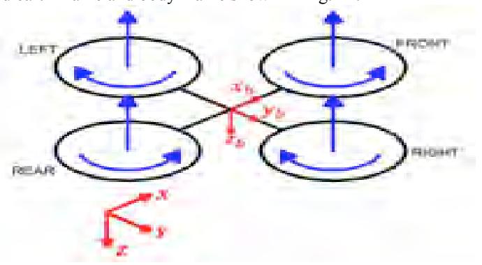
Quadrotor dynamic behavior can be modeled as a 6-DOF rigid body [paper2] and a MIMO control unit is required to control it. Fig. 15 shows the low level control system of a quadrotor.
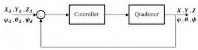
In high level control unit, navigation information and orders received from artificial intelligence (AI) unit are taken to account and the decision effects of the quadrotor behavior [paper 3, paper 4].
7. Localization and Mapping
Localization and map building is an important task of mobile robots. A precise and stable self localization is a key feature to act successfully in an unknown environment. Dead reckoning such as odometry (wheel rotation count) may conventionally be used, to estimate a robot position. Due to unbounded position error generated by the odometry, it doesn't suffice alone for localization. A possible way to enhance localization is to use laser scan matching. Compared to other sensors, laser scanners have unique advantages such as: dense and accurate range measurement, high sampling rate, excessive angular resolution, as well as good range and distance resolution. In laser scan matching, the position and orientation or pose of the current scan is sought with respect to a reference laser scan. The pose of the current scan is adjusted until the best overlap with the reference scan is achieved.
Laser scan matching methods are categorized based on their association: point to point and feature to feature. The point to point matching approach [1],[2],[3], is to approximate the alignment of two consecutive scans, and then iteratively improve the alignment by defining and minimizing a distance between the scans. Moreover, it does not require the environment to be structured or contain predefined features. In the feature to feature matching approach, instead of working directly with raw scan points, the raw scans are transformed into geometric features. These extracted features are used in matching at the next step. Such approaches interpret laser scans and require the presence of chosen features in the environment. Features such as line segments [4][5], corners [6] or range extrema are extracted from laser scans, and matched. Features require less memory space while provide rich and accurate information.
To achieve our goal in improving localization, we implemented an iterative closest point (ICP) [1] and TrimmedICP algorithm which is based on point to point matching.
A common feature of most ICP versions is the usage of the Euclidean distance to establish the correspondences and to apply the least squares . However, as pointed out by [1], the limitation of this distance is that it does not take into account the sensor rotation. Following the example outlined by [1], show how with Euclidean distance, points far from the sensor could be far from its correspondent due to rotations of the sensor, and how the associations could not clearly explain the motion (again due to rotations). MbICP understand that this is a central problem of the ICP algorithms: to find a way to measure (to find the closest correspondent and to apply the minimization) in such a way that it captures the sensor translation and rotation at the same time. MbICP defended a new distance measure in the sensor configuration space that takes into account both translation and rotation at the same time.
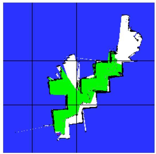
You can find a compression between ICP, IDC and MbICP in [1]. We are now working to implementing MbICP for scan matching. Fig 16 shows result of our implementations in real arena in China 2008.
8. Map merging algorithm
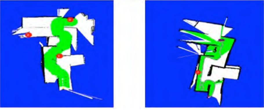
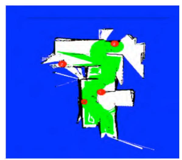
We employed an autonomous robot and two tele-operated robots for the competitions, therefore, at least two maps will be generated in the arena. For merging these maps we designed n GUI. Using this GUI, the operator can merge maps in mission time limitation. Fig. 17 illustrates two independent maps generated by two robots and in Fig. 18 two maps are merged.
9. Victim Identification
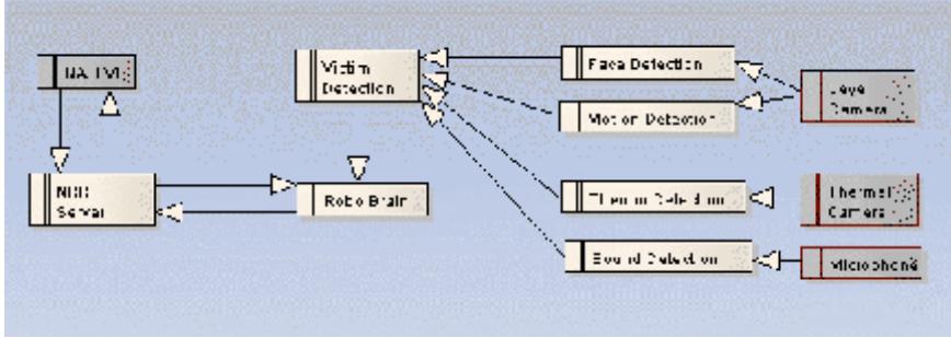
For victim identification we have used a set of different sensors based on victim's characteristics such as shape (face, hand, body ...), hate, sound, CO2 and motion. For example image processing includes shape detection, texture extraction and color segmentation.
10. Robot Locomotion
All Tele-Operated robots are equipped to caterpillar locomotion system and autonomous robots have wheeled based locomotion system.
11. Team Training for Operation (Human Factors)
Our goal is developing a user friendly GUI system with minimum operator training requirement. It has straightforward drive and control and the complex systems like mapping are independent from diver and carried out autonomously.
12. Possibility for Practical Application to Real Disaster Site
Our Tele-Operated robots are designed for practical application at a real disaster site and they had good performance in real tests but the autonomous robots need more develops specially in mapping and exploration algorithms and are under progress.
13. System Cost
Most of the mechanical parts of the robots are designed and built by our team members. Depends on the type of the motor we have bought our DC servomotors from Faulhaber, Maxon and Dunkermotoren company. Ultrasonic sensors, Motor Driver MD03 and digital compass are bought from Devantech Robot-Electronics. Other sensors, Wireless-LAN card and electronics parts are bought from local shop. The cost for each robot differs depending on the size and complexity of the robot but approximately each robot cost us about 9000-15000 $US.
14. Lessons Learned
The urban search and rescue (USAR) robot requires capabilities in mobility, sensory perception, planning, mapping, and practical operator interfaces, while searching for victims in unstructured environments. So the robots should have high power and flexible mechanism to overcome the hard obstacles and it should be intelligent in control and map generation and victim detection as well. In the case of full autonomous robots the victim detection, path finding and exploration in an unknown area are the critical problems.
References
[1]. F. Lu and E. Milios. Robot Pose Estimation in Unknown Environments by Matching 2D Range Scans. In Proc. of the IEEE Computer Society Conference on Computer Vision and Pattern Recognition, pages 935–938, 1994. [2]. A.t Diosi and L. Kleeman. Laser Scan Matching in Polar Coordinates with Application to SLAM. In Proc. of the IEEE/RSJ International Conference on Intelligent Robots and Systems, IROS, 2005. [3]. Bevington, P.R. and D.K. Robinson, Data Reduction and Error Analysis for the Physical Sciences, 2nd Ed., WCB/McGraw-Hill, Boston, 1992. pp 96-115, pp 194-214 [4]. S. T. Pfister, S. I. Roumeliotis, and J. W. Burdick. Weighted Line Fitting Algorithms for Mobile Robot Map Building and Efficient Data Representation. In Proc. of the IEEE/ICRA International Conference on Robotics and Automation, 2003. [5]. V. Nguyen, A. Martinelli, N. Tomatis, R. Siegwart. A Comparison of Line Extraction Algorithms using 2D Laser Rangefinder for Indoor Mobile Robotics. In Proc. of the IEEE/RSJ International Conference on Intelligent Robots and Systems, IROS, 2005. [6]. M. Norouzi, M. Yaghobi, M. Rezaei, M. Jadaliha. "Recursive Line Extraction Algorithm from 2D Laser Scanner Applied to Navigation a Mobile Robot", In Proceedings of the IEEE International Conference on Robotics and Biomimetics, ROBIO, 2008 [7]. M. Yaghobi, M. Jadaliha, J. Zolghadr, M. Norouzi. "Adaptive Line Extraction Algorithm for SLAM Application", In Proceedings of the IEEE International Conference on Robotics and Biomimetics, ROBIO, 2008 [8]. M. Norouzi, A. Karambakhsh, M. Namazifarr. "Object Based Navigation of Mobile Robot with Obstacle Avoidance using Fuzzy Controller", Accepted in the 7th IEEE International Conference on Control & Automation (ICCA'2009) [Paper1]. Gabriel M. Hoffmann, Haomiao Huang, Steven L. Waslander, and Claire J. Tomlin, "Quadrotor Helicopter Flight Dynamics and Control: Theory and Experiment," AIAA Guidance, Navigation and Control Conference and Exhibit, 20-23 August 2007, South Carolina. [paper2]. Bresciani, Tommaso, "Modelling, Identification and Control of a Quadrotor Helicopter," Master Thesis, Lund University, Department of Automatic Control, October 2008. [Paper3]. Farshid Jafari Harandi, Vahid Khorani, and Alireza Mohammad Shahri, "Modeling, Simulation and Implementation of a Quadrotor," RoboCup Iran Open Symposiom, Tehran, 5-9 April 2010. [Paper4]. Vahid Khorani, Alireza Mohammad Shahri, Arash Shirkhorshidi, Seyyed Mohammad Reza Mirfakhar, "Localization and Control of the Quadrotor using IMU and Mono Camera," RoboCup Iran Open Symposiom, Tehran, 5-9 April 2011.